DIGITAL CAMERA FOR PROCESSING AND PRINTING IMAGES
US20100208085A1
2010-08-19
12/769,643
2010-04-28
Abstract:
A digital camera for processing and printing an image is provided having an image sensor for capturing image data from images sensed at an auto exposure setting, an image processor for processing the image to produce processed data, a printer for printing the processed data, and an interface for receiving a cartridge having postcard media and memory storing information regarding a size of each postcard. The image processor produces the processed data using the auto exposure setting and the information regarding the size of each postcard read from the cartridge memory.
Interested in similar patents?
Get notified when new applications in this technology area are published.
Classification:
B41J2/17513 » CPC main
Typewriters or selective printing mechanisms characterised by the printing or marking process for which they are designed characterised by bringing liquid or particles selectively into contact with a printing material; Ink jet characterised by ink handling; Ink supply systems ; Circuit parts therefor; Ink cartridges Inner structure
G06F21/79 » CPC further
Security arrangements for protecting computers, components thereof, programs or data against unauthorised activity; Protecting specific internal or peripheral components, in which the protection of a component leads to protection of the entire computer to assure secure storage of data in semiconductor storage media, e.g. directly-addressable memories
G06F21/86 » CPC further
Security arrangements for protecting computers, components thereof, programs or data against unauthorised activity; Protecting specific internal or peripheral components, in which the protection of a component leads to protection of the entire computer Secure or tamper-resistant housings
G06K1/121 » CPC further
Methods or arrangements for marking the record carrier in digital fashion otherwise than by punching by printing code marks
G06K7/14 » CPC further
Methods or arrangements for sensing record carriers, e.g. for reading patterns by electromagnetic radiation, e.g. optical sensing; by corpuscular radiation using light without selection of wavelength, e.g. sensing reflected white light
G06K7/1417 » CPC further
Methods or arrangements for sensing record carriers, e.g. for reading patterns by electromagnetic radiation, e.g. optical sensing; by corpuscular radiation using light without selection of wavelength, e.g. sensing reflected white light; Methods for optical code recognition the method being specifically adapted for the type of code 2D bar codes
G06K19/06037 » CPC further
Record carriers for use with machines and with at least a part designed to carry digital markings characterised by the kind of the digital marking, e.g. shape, nature, code with optically detectable marking multi-dimensional coding
G07F7/08 » CPC further
Mechanisms actuated by objects other than coins to free or to actuate vending, hiring, coin or paper currency dispensing or refunding apparatus by coded identity card or credit card or other personal identification means
G07F7/086 » CPC further
Mechanisms actuated by objects other than coins to free or to actuate vending, hiring, coin or paper currency dispensing or refunding apparatus by coded identity card or credit card or other personal identification means by passive credit-cards adapted therefor, e.g. constructive particularities to avoid counterfeiting, e.g. by inclusion of a physical or chemical security-layer
G07F7/12 » CPC further
Mechanisms actuated by objects other than coins to free or to actuate vending, hiring, coin or paper currency dispensing or refunding apparatus by coded identity card or credit card or other personal identification means Card verification
G11C11/56 » CPC further
Digital stores characterised by the use of particular electric or magnetic storage elements; Storage elements therefor using storage elements with more than two stable states represented by steps, e.g. of voltage, current, phase, frequency
H04N1/0044 » CPC further
Scanning, transmission or reproduction of documents or the like, e.g. facsimile transmission; Details thereof; User-machine interface; Control console; Output means; Display of information to the user, e.g. menus for image preview or review, e.g. to help the user position a sheet
H04N1/2112 » CPC further
Scanning, transmission or reproduction of documents or the like, e.g. facsimile transmission; Details thereof; Intermediate information storage for one or a few pictures using still video cameras
H04N1/2154 » CPC further
Scanning, transmission or reproduction of documents or the like, e.g. facsimile transmission; Details thereof; Intermediate information storage for one or a few pictures using still video cameras the still video camera incorporating a hardcopy reproducing device, e.g. a printer
H04N5/235 » CPC further
Details of television systems; Studio circuitry; Studio devices; Studio equipment ; Cameras comprising an electronic image sensor, e.g. digital cameras, video cameras, TV cameras, video cameras, camcorders, webcams, camera modules for embedding in other devices, e.g. mobile phones, computers or vehicles; Television cameras ; Cameras comprising an electronic image sensor, e.g. digital cameras, video cameras, camcorders, webcams, camera modules specially adapted for being embedded in other devices, e.g. mobile phones, computers or vehicles Circuitry for compensating for variation in the brightness of the object
H04N5/2628 » CPC further
Details of television systems; Studio circuitry; Studio devices; Studio equipment ; Cameras comprising an electronic image sensor, e.g. digital cameras, video cameras, TV cameras, video cameras, camcorders, webcams, camera modules for embedding in other devices, e.g. mobile phones, computers or vehicles; Studio circuits, e.g. for mixing, switching-over, change of character of image, other special effects ; Cameras specially adapted for the electronic generation of special effects Alteration of picture size, shape, position or orientation, e.g. zooming, rotation, rolling, perspective, translation
B41J2/16585 » CPC further
Typewriters or selective printing mechanisms characterised by the printing or marking process for which they are designed characterised by bringing liquid or particles selectively into contact with a printing material; Ink jet; Nozzles; Preventing or detecting of nozzle clogging, e.g. cleaning, capping or moistening for nozzles for paper-width or non-reciprocating print heads
B41J2/17596 » CPC further
Typewriters or selective printing mechanisms characterised by the printing or marking process for which they are designed characterised by bringing liquid or particles selectively into contact with a printing material; Ink jet characterised by ink handling; Ink supply systems ; Circuit parts therefor Ink pumps, ink valves
B41J2202/21 » CPC further
Embodiments of or processes related to ink-jet or thermal heads; Embodiments of or processes related to ink-jet heads Line printing
G06F2221/2129 » CPC further
Indexing scheme relating to security arrangements for protecting computers, components thereof, programs or data against unauthorised activity; Indexing scheme relating to and subgroups addressing additional information or applications relating to security arrangements for protecting computers, components thereof, programs or data against unauthorised activity Authenticate client device independently of the user
H04N2101/00 » CPC further
Still video cameras
H04N5/225 » CPC further
Details of television systems; Studio circuitry; Studio devices; Studio equipment ; Cameras comprising an electronic image sensor, e.g. digital cameras, video cameras, TV cameras, video cameras, camcorders, webcams, camera modules for embedding in other devices, e.g. mobile phones, computers or vehicles Television cameras ; Cameras comprising an electronic image sensor, e.g. digital cameras, video cameras, camcorders, webcams, camera modules specially adapted for being embedded in other devices, e.g. mobile phones, computers or vehicles
Description
CROSS REFERENCES TO RELATED APPLICATIONS
The present application is a continuation of U.S. application Ser. No. 10/831,234 filed on Apr. 26, 2004, which is a Continuation-in-Part of U.S. application Ser. No. 09/112,743 filed on Jul. 10, 1998, now issued U.S. Pat. No. 6,727,951 all of which are herein incorporated by reference.
FIELD OF THE INVENTION
The present invention relates to digital cameras and in particular, the onboard processing and printing of images captured by the camera.
BACKGROUND OF THE INVENTION
Recently, digital cameras have become increasingly popular. These cameras normally operate by means of imaging a desired image utilising a charge coupled device (CCD) array and storing the imaged scene on an electronic storage medium for later down loading onto a computer system for subsequent manipulation and printing out. Normally, when utilising a computer system to print out an image, sophisticated software may available to manipulate the image in accordance with requirements.
Unfortunately such systems require significant post processing of a captured image and normally present the image in an orientation to which it was taken, relying on the post processing process to perform any necessary or required modifications of the captured image. Further, much of the environmental information available when the picture was taken is lost.
SUMMARY OF THE INVENTION
It is an object of the present invention to provide for the utilisation of exposure information in an image specific manner.
Accordingly, the present invention provides a digital camera for sensing and storing an image, the camera comprising:
an image sensor with a charge coupled device (CCD) for capturing image data relating to a sensed image, and an auto exposure setting for adjusting the image data captured by the CCD in response to the lighting conditions at image capture; and,
an image processor for processing image data from the CCD and storing the processed data; wherein,
the image processor is adapted to use information from the auto exposure setting relating to the lighting conditions at image capture when processing the image data from the CCD.
Utilising the auto exposure setting to determine an advantageous re-mapping of colours within the image allows the processor to produce an amended image having colours within an image transformed to account of the auto exposure setting. The processing can comprise re-mapping image colours so they appear deeper and richer when the exposure setting indicates low light conditions and re-mapping image colours to be brighter and more saturated when the auto exposure setting indicates bright light conditions.
BRIEF DESCRIPTION OF DRAWINGS
Notwithstanding any other forms which may fall within the scope of the present invention, preferred forms of the invention will now be described, by way of example only, with reference to the accompanying drawings which:
FIG. 1 is a block diagram of a digital camera of the preferred embodiment;
FIG. 2 illustrates a form of print roll ready for purchase by a consumer;
FIG. 3 illustrates a perspective view, partly in section, of an alternative form of a print roll;
FIG. 4 is a left side exploded perspective view of the print roll of FIG. 3; and,
FIG. 5 is a right side exploded perspective view of a single print roll.
DESCRIPTION OF PREFERRED AND OTHER EMBODIMENTS
The preferred embodiment is preferable implemented through suitable programming of a hand held camera device such as that described in the present applicant's application entitled “A Digital Image Printing Camera with Image Processing Capability”, the content of which is hereby specifically incorporated by cross reference and the details of which, and other related applications are set out in the tables below.
The aforementioned patent specification discloses a camera system, hereinafter known as an “Artcam” type camera, wherein sensed images can be directly printed out by an Artcam portable camera unit. Further, the aforementioned specification discloses means and methods for performing various manipulations on images captured by the camera sensing device leading to the production of various effects in any output image. The manipulations are disclosed to be highly flexible in nature and can be implemented through the insertion into the Artcam of cards having encoded thereon various instructions for the manipulation of images, the cards hereinafter being known as Artcards. The Artcam further has significant onboard processing power by an Artcam Central Processor unit (ACP) which is interconnected to a memory device for the storage of important data and images.
In the preferred embodiment, the Artcam has an auto exposure sensor for determining the light level associated with the captured image. This auto exposure sensor is utilised to process the image in accordance with the set light value so as to enhance portions of the image.
Preferably, the area image sensor includes a means for determining the light conditions when capturing an image. The area image sensor adjusts the dynamic range of values captured by the CCD in accordance with the detected level sensor. The captured image is transferred to the Artcam central processor and stored in the memory store. Intensity information, as determined by the area image sensor, is also forwarded top the ACP. This information is utilised by the Artcam central processor to manipulate the stored image to enhance certain effects.
Turning now to FIG. 1, Artcam 20 is illustrated in which auto exposure setting information 1 is utilised in conjunction with stored image 2 to process the image by utilising ACP 3. The processed image is returned to the memory store 2 for later printing out on printer 4 or printed directly.
A number of processing steps can be undertaken in accordance with the determined light conditions. Where the auto exposure setting 1 indicates that the image was taken in a low light condition, the image pixel colours are selectively re-mapped so as to make the image colours stronger, deeper and richer.
Where the auto exposure information indicates that highlight conditions were present when the image was taken, the image colours can be processed to make them brighter and more saturated. The re-colouring of the image can be undertaken by conversion of the image to a hue-saturation-value (HSV) format and an alteration of pixel values in accordance with requirements. The pixel values can then be output converted to the required output colour format of printing.
Of course, many different re-colouring techniques may be utilised. Preferably, the techniques are clearly illustrated on the pre-requisite Artcard inserted into the reader. Alternatively, the image processing algorithms can be automatically applied and hard-wired into the camera for utilization in certain conditions.
Alternatively, the Artcard inserted could have a number of manipulations applied to the image which are specific to the auto-exposure setting. For example, clip arts containing candles etc could be inserted in a dark image and large suns inserted in bright images.
Referring now to FIGS. 2 to 5, the Artcam prints the images onto media stored in a replaceable print roll 5. In some preferred embodiments, the operation of the camera device is such that when a series of images is printed on a first surface of the print roll, the corresponding backing surface has a ready made postcard which can be immediately dispatched at the nearest post office box within the jurisdiction. In this way, personalized postcards can be created.
It would be evident that when utilising the postcard system as illustrated FIG. 2 only predetermined image sizes are possible as the synchronization between the backing postcard portion and the front image must be maintained. This can be achieved by utilising the memory portions of the authentication chip stored within the print roll 5 to store details of the length of each postcard backing format sheet. This can be achieved by either having each postcard the same size or by storing each size within the print rolls on-board print chip memory.
In an alternative embodiment, there is provided a modified form of print roll which can be constructed mostly from injection moulded plastic pieces suitably snapped fitted together. The modified form of print roll has a high ink storage capacity in addition to a somewhat simplified construction. The print media onto which the image is to be printed is wrapped around a plastic sleeve former for simplified construction. The ink media reservoir has a series of air vents which are constructed so as to minimise the opportunities for the ink flow out of the air vents. Further, a rubber seal is provided for the ink outlet holes with the rubber seal being pierced on insertion of the print roll into a camera system. Further, the print roll includes a print media ejection slot and the ejection slot includes a surrounding moulded surface which provides and assists in the accurate positioning of the print media ejection slot relative to the printhead within the printing or camera system.
Turning to FIG. 3 there is illustrated a single point roll unit 5 in an assembled form with a partial cutaway showing internal portions of the print roll. FIG. 4 and FIG. 5 illustrate left and right side exploded perspective views respectively. The print roll 5 is constructed around the internal core portion 6 which contains an internal ink supply. Outside of the core portion 6 is provided a former 7 around which is wrapped a paper or film supply 8. Around the paper supply it is constructed two cover pieces 9, 10 which snap together around the print roll so as to form a covering unit as illustrated in FIG. 3. The bottom cover piece 10 includes a slot 11 through which the output of the print media 12 for interconnection with the camera system.
Two pinch rollers 13, 14 are provided to pinch the paper against a drive pinch roller 15 so they together provide for a decurling of the paper around the roller 15. The decurling acts to negate the strong curl that may be imparted to the paper from being stored in the form of print roll for an extended period of time. The rollers 13, 14 are provided to form a snap fit with end portions of the cover base portion 10 and the roller 15 which includes a cogged end 16 for driving, snap fits into the upper cover piece 9 so as to pinch the paper 12 firmly between.
The cover pieces 9, 10 includes an end protuberance or lip 17. The end lip 17 is provided for accurately alignment of the exit hole of the paper with a corresponding printing heat platen structure within the camera system. In this way, accurate alignment or positioning of the exiting paper relative to an adjacent printhead is provided for full guidance of the paper to the printhead.
It would be appreciated by a person skilled in the art that numerous variations and/or modifications may be made to the present invention as shown in the specific embodiment without departing from the spirit or scope of the invention as broadly described. The present embodiment is, therefore, to be considered in all respects to be illustrative and not restrictive.
The present invention is best utilized in the Artcam device, the details of which are set out in the following paragraphs.
Ink Jet Technologies
The embodiments of the invention use an ink jet printer type device. Of course many different devices could be used. However presently popular ink jet printing technologies are unlikely to be suitable.
The most significant problem with thermal inkjet is power consumption. This is approximately 100 times that required for high speed, and stems from the energy-inefficient means of drop ejection. This involves the rapid boiling of water to produce a vapor bubble which expels the ink. Water has a very high heat capacity, and must be superheated in thermal inkjet applications. This leads to an efficiency of around 0.02%, from electricity input to drop momentum (and increased surface area) out.
The most significant problem with piezoelectric inkjet is size and cost. Piezoelectric crystals have a very small deflection at reasonable drive voltages, and therefore require a large area for each nozzle. Also, each piezoelectric actuator must be connected to its drive circuit on a separate substrate. This is not a significant problem at the current limit of around 300 nozzles per print head, but is a major impediment to the fabrication of pagewide print heads with 19,200 nozzles.
Ideally, the inkjet technologies used meet the stringent requirements of in-camera digital color printing and other high quality, high speed, low cost printing applications. To meet the requirements of digital photography, new inkjet technologies have been created. The target features include:
low power (less than 10 Watts)
high resolution capability (1,600 dpi or more)
photographic quality output
low manufacturing cost
small size (pagewidth times minimum cross section)
high speed (<2 seconds per page).
All of these features can be met or exceeded by the inkjet systems described below with differing levels of difficulty. 45 different inkjet technologies have been developed by the Assignee to give a wide range of choices for high volume manufacture. These technologies form part of separate applications assigned to the present Assignee as set out in the table below.
The inkjet designs shown here are suitable for a wide range of digital printing systems, from battery powered one-time use digital cameras, through to desktop and network printers, and through to commercial printing systems
For ease of manufacture using standard process equipment, the print head is designed to be a monolithic 0.5 micron CMOS chip with MEMS post processing. For color photographic applications, the print head is 100 mm long, with a width which depends upon the inkjet type. The smallest print head designed is IJ38, which is 0.35 mm wide, giving a chip area of 35 square mm. The print heads each contain 19,200 nozzles plus data and control circuitry.
Ink is supplied to the back of the print head by injection molded plastic ink channels. The molding requires 50 micron features, which can be created using a lithographically micromachined insert in a standard injection molding tool. Ink flows through holes etched through the wafer to the nozzle chambers fabricated on the front surface of the wafer. The print head is connected to the camera circuitry by tape automated bonding.
CROSS-REFERENCED APPLICATIONS
The following table is a guide to cross-referenced patent applications filed concurrently herewith and discussed hereinafter with the reference being utilized in subsequent tables when referring to a particular case:
| Docket | ||
| No. | Reference | Title |
| IJ01US | 6,227,652 | Radiant Plunger Ink Jet Printer |
| IJ02US | 6,213,588 | Electrostatic Ink Jet Printer |
| IJ03US | 6,213,589 | Planar Thermoelastic Bend Actuator Ink Jet |
| IJ04US | 6,231,163 | Stacked Electrostatic Ink Jet Printer |
| IJ05US | 6,247,795 | Reverse Spring Lever Ink Jet Printer |
| IJ06US | 6,394,581 | Paddle Type Ink Jet Printer |
| IJ07US | 6,244,691 | Permanent Magnet Electromagnetic Ink Jet Printer |
| IJ08US | 6,257,704 | Planar Swing Grill Electromagnetic Ink Jet Printer |
| IJ09US | 6,416,168 | Pump Action Refill Ink Jet Printer |
| IJ10US | 6,220,694 | Pulsed Magnetic Field Ink Jet Printer |
| IJ11US | 6,257,705 | Two Plate Reverse Firing Electromagnetic Ink Jet |
| Printer | ||
| IJ12US | 6,247,794 | Linear Stepper Actuator Ink Jet Printer |
| IJ13US | 6,234,610 | Gear Driven Shutter Ink Jet Printer |
| IJ14US | 6,247,793 | Tapered Magnetic Pole Electromagnetic Ink Jet |
| Printer | ||
| IJ15US | 6,264,306 | Linear Spring Electromagnetic Grill Ink Jet |
| Printer | ||
| IJ16US | 6,241,342 | Lorenz Diaphragm Electromagnetic Ink Jet Printer |
| IJ17US | 6,247,792 | PTFE Surface Shooting Shuttered Oscillating |
| Pressure Ink Jet Printer | ||
| IJ18US | 6,264,307 | Buckle Grip Oscillating Pressure Ink Jet Printer |
| IJ19US | 6,254,220 | Shutter Based Ink Jet Printer |
| IJ20US | 6,234,611 | Curling Calyx Thermoelastic Ink Jet Printer |
| IJ21US | 6,302,528 | Thermal Actuated Ink Jet Printer |
| IJ22US | 6,283,582 | Iris Motion Ink Jet Printer |
| IJ23US | 6,239,821 | Direct Firing Thermal Bend Actuator Ink Jet |
| Printer | ||
| IJ24US | 6,338,547 | Conductive PTFE Ben Activator Vented Ink Jet |
| Printer | ||
| IJ25US | 6,247,796 | Magnetostrictive Ink Jet Printer |
| IJ26US | 6,557,977 | Shape Memory Alloy Ink Jet Printer |
| IJ27US | 6,390,603 | Buckle Plate Ink Jet Printer |
| IJ28US | 6,362,843 | Thermal Elastic Rotary Impeller Ink Jet Printer |
| IJ29US | 6,293,653 | Thermoelastic Bend Actuator Ink Jet Printer |
| IJ30US | 6,312,107 | Thermoelastic Bend Actuator Using PTFE and |
| Corrugated Copper Ink Jet Printer | ||
| IJ31US | 6,227,653 | Bend Actuator Direct Ink Supply Ink Jet Printer |
| IJ32US | 6,234,609 | A High Young's Modulus Thermoelastic Ink Jet |
| Printer | ||
| IJ33US | 6,238,040 | Thermally actuated slotted chamber wall ink jet |
| printer | ||
| IJ34US | 6,188,415 | Ink Jet Printer having a thermal actuator |
| comprising an external coiled spring | ||
| IJ35US | 6,227,654 | Trough Container Ink Jet Printer |
| IJ36US | 6,209,989 | Dual Chamber Single Vertical Actuator Ink Jet |
| IJ37US | 6,247,791 | Dual Nozzle Single Horizontal Fulcrum Actuator |
| Ink Jet | ||
| IJ38US | 6,336,710 | Dual Nozzle Single Horizontal Actuator Ink Jet |
| IJ39US | 6,217,153 | A single bend actuator cupped paddle ink jet |
| printing device | ||
| IJ40US | 6,416,167 | A thermally actuated ink jet printer having a |
| series of thermal actuator units | ||
| IJ41US | 6,243,113 | A thermally actuated ink jet printer including a |
| tapered heater element | ||
| IJ42US | 6,283,581 | Radial Back-Curling Thermoelastic Ink Jet |
| IJ43US | 6,247,790 | Inverted Radial Back-Curling Thermoelastic Ink Jet |
| IJ44US | 6,260,953 | Surface bend actuator vented ink supply ink jet |
| printer | ||
| IJ45US | 6,267,469 | Coil Acutuated Magnetic Plate Ink Jet Printer |
Tables of Drop-on-Demand Inkjets
Eleven important characteristics of the fundamental operation of individual inkjet nozzles have been identified. These characteristics are largely orthogonal, and so can be elucidated as an eleven dimensional matrix. Most of the eleven axes of this matrix include entries developed by the present assignee.
The following tables form the axes of an eleven dimensional table of inkjet types.
| Actuator mechanism | (18 types) | |
| Basic operation mode | (7 types) | |
| Auxiliary mechanism | (8 types) | |
| Actuator amplification or modification method | (17 types) | |
| Actuator motion | (19 types) | |
| Nozzle refill method | (4 types) | |
| Method of restricting back-flow through inlet | (10 types) | |
| Nozzle clearing method | (9 types) | |
| Nozzle plate construction | (9 types) | |
| Drop ejection direction | (5 types) | |
| Ink type | (7 types) | |
The complete eleven dimensional table represented by these axes contains 36.9 billion possible configurations of inkjet nozzle. While not all of the possible combinations result in a viable inkjet technology, many million configurations are viable. It is clearly impractical to elucidate all of the possible configurations. Instead, certain inkjet types have been investigated in detail. These are designated IJ01 to IJ45 above.
Other inkjet configurations can readily be derived from these 45 examples by substituting alternative configurations along one or more of the 11 axes. Most of the IJ01 to IJ45 examples can be made into inkjet print heads with characteristics superior to any currently available inkjet technology.
Where there are prior art examples known to the inventor, one or more of these examples are listed in the examples column of the tables below. The IJ01 to IJ45 series are also listed in the examples column. In some cases, a printer may be listed more than once in a table, where it shares characteristics with more than one entry.
Suitable applications include: Home printers, Office network printers, Short run digital printers, Commercial print systems, Fabric printers, Pocket printers, Internet WWW printers, Video printers, Medical imaging, Wide format printers, Notebook PC printers, Fax machines, Industrial printing systems, Photocopiers, Photographic minilabs etc.
The information associated with the aforementioned 11 dimensional matrix are set out in the following tables.
Actuator Mechanism (Applied Only to Selected Ink Drops)
| Actuator | ||
| Mechanism | Description | Advantages |
| Thermal bubble | An electrothermal heater heats the ink to | Large force generated |
| above boiling point, transferring | Simple construction | |
| significant heat to the aqueous ink. A | No moving parts | |
| bubble nucleates and quickly forms, | Fast operation | |
| expelling the ink. | Small chip area required for | |
| The efficiency of the process is low, with | actuator | |
| typically less than 0.05% of the electrical | ||
| energy being transformed into kinetic energy | ||
| of the drop. | ||
| Piezoelectric | A piezoelectric crystal such as lead | Low power consumption |
| lanthanum zirconate (PZT) is electrically | Many ink types can be used | |
| activated, and either expands, shears, or | Fast operation | |
| bends to apply pressure to the ink, | High efficiency | |
| ejecting drops. | ||
| Electro-strictive | An electric field is used to activate | Low power consumption |
| electrostriction in relaxor materials such | Many ink types can be used | |
| as lead lanthanum zirconate titanate | Low thermal expansion | |
| (PLZT) or lead magnesium niobate | Electric field strength required | |
| (PMN). | (approx. 3.5 V/μm) can be | |
| generated without difficulty | ||
| Does not require electrical | ||
| poling | ||
| Ferroelectric | An electric field is used to induce a | Low power consumption |
| phase transition between the | Many ink types can be used | |
| antiferroelectric (AFE) and ferroelectric | Fast operation (<1 μs) | |
| (FE) phase. Perovskite materials such as | Relatively high longitudinal | |
| tin modified lead lanthanum zirconate | strain | |
| titanate (PLZSnT) exhibit large strains of | High efficiency | |
| up to 1% associated with the AFE to FE | Electric field strength of | |
| phase transition. | around 3 V/μm can be readily | |
| provided | ||
| Electrostatic | Conductive plates are separated by a | Low power consumption |
| plates | compressible or fluid dielectric (usually | Many ink types can be used |
| air). Upon application of a voltage, the | Fast operation | |
| plates attract each other and displace ink, | ||
| causing drop ejection. The conductive | ||
| plates may be in a comb or honeycomb | ||
| structure, or stacked to increase the | ||
| surface area and therefore the force. | ||
| Electrostatic | A strong electric field is applied to the | Low current consumption |
| pull on ink | ink, whereupon electrostatic attraction | Low temperature |
| accelerates the ink towards the print | ||
| medium. | ||
| Permanent | An electromagnet directly attracts a | Low power consumption |
| magnet electro- | permanent magnet, displacing ink and | Many ink types can be used |
| magnetic | causing drop ejection. Rare earth | Fast operation |
| magnets with a field strength around 1 | High efficiency | |
| Tesla can be used. Examples are: | Easy extension from single | |
| Samarium Cobalt (SaCo) and magnetic | nozzles to pagewidth print | |
| materials in the neodymium iron boron | heads | |
| family (NdFeB, NdDyFeBNb, | ||
| NdDyFeB, etc) | ||
| Soft magnetic | A solenoid induced a magnetic field in a | Low power consumption |
| core electro- | soft magnetic core or yoke fabricated | Many ink types can be used |
| magnetic | from a ferrous material such as | Fast operation |
| electroplated iron alloys such as CoNiFe | High efficiency | |
| [1], CoFe, or NiFe alloys. Typically, the | Easy extension from single | |
| soft magnetic material is in two parts, | nozzles to pagewidth print | |
| which are normally held apart by a | heads | |
| spring. When the solenoid is actuated, | ||
| the two parts attract, displacing the ink. | ||
| Magnetic | The Lorenz force acting on a current | Low power consumption |
| Lorenz force | carrying wire in a magnetic field is | Many ink types can be used |
| utilized. | Fast operation | |
| This allows the magnetic field to be | High efficiency | |
| supplied externally to the print head, for | Easy extension from single | |
| example with rare earth permanent | nozzles to pagewidth print | |
| magnets. | heads | |
| Only the current carrying wire need be | ||
| fabricated on the print-head, simplifying | ||
| materials requirements. | ||
| Magneto- | The actuator uses the giant | Many ink types can be used |
| striction | magnetostrictive effect of materials such | Fast operation |
| as Terfenol-D (an alloy of terbium, | Easy extension from single | |
| dysprosium and iron developed at the | nozzles to pagewidth print | |
| Naval Ordnance Laboratory, hence Ter- | heads | |
| Fe-NOL). For best efficiency, the | High force is available | |
| actuator should be pre-stressed to | ||
| approx. 8 MPa. | ||
| Surface tension | Ink under positive pressure is held in a | Low power consumption |
| reduction | nozzle by surface tension. The surface | Simple construction |
| tension of the ink is reduced below the | No unusual materials required | |
| bubble threshold, causing the ink to | in fabrication | |
| egress from the nozzle. | High efficiency | |
| Easy extension from single | ||
| nozzles to pagewidth print | ||
| heads | ||
| Viscosity | The ink viscosity is locally reduced to | Simple construction |
| reduction | select which drops are to be ejected. A | No unusual materials required |
| viscosity reduction can be achieved | in fabrication | |
| electrothermally with most inks, but | Easy extension from single | |
| special inks can be engineered for a | nozzles to pagewidth print | |
| 100:1 viscosity reduction. | heads | |
| Acoustic | An acoustic wave is generated and | Can operate without a nozzle |
| focussed upon the drop ejection region. | plate | |
| Thermoelastic | An actuator which relies upon | Low power consumption |
| bend actuator | differential thermal expansion upon | Many ink types can be used |
| Joule heating is used. | Simple planar fabrication | |
| Small chip area required for | ||
| each actuator | ||
| Fast operation | ||
| High efficiency | ||
| CMOS compatible voltages | ||
| and currents | ||
| Standard MEMS processes can | ||
| be used | ||
| Easy extension from single | ||
| nozzles to pagewidth print | ||
| heads | ||
| High CTE | A material with a very high coefficient | High force can be generated |
| thermoelastic | of thermal expansion (CTE) such as | PTFE is a candidate for low |
| actuator | polytetrafluoroethylene (PTFE) is used. | dielectric constant insulation in |
| As high CTE materials are usually non- | ULSI | |
| conductive, a heater fabricated from a | Very low power consumption | |
| conductive material is incorporated. A | Many ink types can be used | |
| 50 μm long PTFE bend actuator with | Simple planar fabrication | |
| polysilicon heater and 15 mW power | Small chip area required for | |
| input can provide 180 μN force and 10 μm | each actuator | |
| deflection. Actuator motions include: | Fast operation | |
| 1) Bend | High efficiency | |
| 2) Push | CMOS compatible voltages | |
| 3) Buckle | and currents | |
| 4) Rotate | Easy extension from single | |
| nozzles to pagewidth print | ||
| heads | ||
| Conductive | A polymer with a high coefficient of | High force can be generated |
| polymer | thermal expansion (such as PTFE) is | Very low power consumption |
| thermoelastic | doped with conducting substances to | Many ink types can be used |
| actuator | increase its conductivity to about 3 | Simple planar fabrication |
| orders of magnitude below that of | Small chip area required for | |
| copper. The conducting polymer | each actuator | |
| expands when resistively heated. | Fast operation | |
| Examples of conducting dopants include: | High efficiency | |
| 1) Carbon nanotubes | CMOS compatible voltages | |
| 2) Metal fibers | and currents | |
| 3) Conductive polymers such as doped | Easy extension from single | |
| polythiophene | nozzles to pagewidth print | |
| 4) Carbon granules | heads | |
| Shape memory | A shape memory alloy such as TiNi (also | High force is available |
| alloy | known as Nitinol - Nickel Titanium alloy | (stresses of hundreds of MPa) |
| developed at the Naval Ordnance | Large strain is available (more | |
| Laboratory) is thermally switched | than 3%) | |
| between its weak martensitic state and its | High corrosion resistance | |
| high stiffness austenic state. The shape | Simple construction | |
| of the actuator in its martensitic state is | Easy extension from single | |
| deformed relative to the austenic shape. | nozzles to pagewidth print | |
| The shape change causes ejection of a | heads | |
| drop. | Low voltage operation | |
| Linear Magnetic | Linear magnetic actuators include the | Linear Magnetic actuators can |
| Actuator | Linear Induction Actuator (LIA), Linear | be constructed with high |
| Permanent Magnet Synchronous | thrust, long travel, and high | |
| Actuator (LPMSA), Linear Reluctance | efficiency using planar | |
| Synchronous Actuator (LRSA), Linear | semiconductor fabrication | |
| Switched Reluctance Actuator (LSRA), | techniques | |
| and the Linear Stepper Actuator (LSA). | Long actuator travel is | |
| available | ||
| Medium force is available | ||
| Low voltage operation | ||
| Actuator | ||
| Mechanism | Disadvantages | Examples |
| Thermal bubble | High power | Canon Bubblejet 1979 |
| Ink carrier limited to water | Endo et al GB patent | |
| Low efficiency | 2,007,162 | |
| High temperatures required | Xerox heater-in-pit | |
| High mechanical stress | 1990 Hawkins et al | |
| Unusual materials required | U.S. Pat. No. 4,899,181 | |
| Large drive transistors | Hewlett-Packard TIJ | |
| Cavitation causes actuator failure | 1982 Vaught et al U.S. Pat. No. | |
| Kogation reduces bubble formation | 4,490,728 | |
| Large print heads are difficult to fabricate | ||
| Piezoelectric | Very large area required for actuator | Kyser et al U.S. Pat. No. |
| Difficult to integrate with electronics | 3,946,398 | |
| High voltage drive transistors required | Zoltan U.S. Pat. No. 3,683,212 | |
| Full pagewidth print heads impractical due | 1973 Stemme U.S. Pat. No. | |
| to actuator size | 3,747,120 | |
| Requires electrical poling in high field | Epson Stylus | |
| strengths during manufacture | Tektronix | |
| IJ04 | ||
| Electro-strictive | Low maximum strain (approx. 0.01%) | Seiko Epson, Usui et all |
| Large area required for actuator due to low | JP 253401/96 | |
| strain | IJ04 | |
| Response speed is marginal (~10 μs) | ||
| High voltage drive transistors required | ||
| Full pagewidth print heads impractical due | ||
| to actuator size | ||
| Ferroelectric | Difficult to integrate with electronics | IJ04 |
| Unusual materials such as PLZSnT are | ||
| required | ||
| Actuators require a large area | ||
| Electrostatic | Difficult to operate electrostatic devices in | IJ02, IJ04 |
| plates | an aqueous environment | |
| The electrostatic actuator will normally | ||
| need to be separated from the ink | ||
| Very large area required to achieve high | ||
| forces | ||
| High voltage drive transistors may be | ||
| required | ||
| Full pagewidth print heads are not | ||
| competitive due to actuator size | ||
| Electrostatic | High voltage required | 1989 Saito et al, U.S. Pat. No. |
| pull on ink | May be damaged by sparks due to air | 4,799,068 |
| breakdown | 1989 Miura et al, U.S. Pat. No. | |
| Required field strength increases as the | 4,810,954 | |
| drop size decreases | Tone-jet | |
| High voltage drive transistors required | ||
| Electrostatic field attracts dust | ||
| Permanent | Complex fabrication | IJ07, IJ10 |
| magnet electro- | Permanent magnetic material such as | |
| magnetic | Neodymium Iron Boron (NdFeB) required. | |
| High local currents required | ||
| Copper metalization should be used for | ||
| long electromigration lifetime and low | ||
| resistivity | ||
| Pigmented inks are usually infeasible | ||
| Operating temperature limited to the Curie | ||
| temperature (around 540 K) | ||
| Soft magnetic | Complex fabrication | IJ01, IJ05, IJ08, IJ10 |
| core electro- | Materials not usually present in a CMOS | IJ12, IJ14, IJ15, IJ17 |
| magnetic | fab such as NiFe, CoNiFe, or CoFe are | |
| required | ||
| High local currents required | ||
| Copper metalization should be used for | ||
| long electromigration lifetime and low | ||
| resistivity | ||
| Electroplating is required | ||
| High saturation flux density is required | ||
| (2.0-2.1 T is achievable with CoNiFe [1]) | ||
| Magnetic | Force acts as a twisting motion | IJ06, IJ11, IJ13, IJ16 |
| Lorenz force | Typically, only a quarter of the solenoid | |
| length provides force in a useful direction | ||
| High local currents required | ||
| Copper metalization should be used for | ||
| long electromigration lifetime and low | ||
| resistivity | ||
| Pigmented inks are usually infeasible | ||
| Magneto- | Force acts as a twisting motion | Fischenbeck, U.S. Pat. No. |
| striction | Unusual materials such as Terfenol-D are | 4,032,929 |
| required | IJ25 | |
| High local currents required | ||
| Copper metalization should be used for | ||
| long electromigration lifetime and low | ||
| resistivity | ||
| Pre-stressing may be required | ||
| Surface tension | Requires supplementary force to effect | Silverbrook, EP 0771 |
| reduction | drop separation | 658 A2 and related |
| Requires special ink surfactants | patent applications | |
| Speed may be limited by surfactant | ||
| properties | ||
| Viscosity | Requires supplementary force to effect | Silverbrook, EP 0771 |
| reduction | drop separation | 658 A2 and related |
| Requires special ink viscosity properties | patent applications | |
| High speed is difficult to achieve | ||
| Requires oscillating ink pressure | ||
| A high temperature difference (typically 80 | ||
| degrees) is required | ||
| Acoustic | Complex drive circuitry | 1993 Hadimioglu et al, |
| Complex fabrication | EUP 550,192 | |
| Low efficiency | 1993 Elrod et al, EUP | |
| Poor control of drop position | 572,220 | |
| Poor control of drop volume | ||
| Thermoelastic | Efficient aqueous operation requires a | IJ03, IJ09, IJ17, IJ18 |
| bend actuator | thermal insulator on the hot side | IJ19, IJ20, IJ21, IJ22 |
| Corrosion prevention can be difficult | IJ23, IJ24, IJ27, IJ28 | |
| Pigmented inks may be infeasible, as | IJ29, IJ30, IJ31, IJ32 | |
| pigment particles may jam the bend | IJ33, IJ34, IJ35, IJ36 | |
| actuator | IJ37, IJ38, IJ39, IJ40 | |
| IJ41 | ||
| High CTE | Requires special material (e.g. PTFE) | IJ09, IJ17, IJ18, IJ20 |
| thermoelastic | Requires a PTFE deposition process, which | IJ21, IJ22, IJ23, IJ24 |
| actuator | is not yet standard in ULSI fabs | IJ27, IJ28, IJ29, IJ30 |
| PTFE deposition cannot be followed with | IJ31, IJ42, IJ43, IJ44 | |
| high temperature (above 350° C.) | ||
| processing | ||
| Pigmented inks may be infeasible, as | ||
| pigment particles may jam the bend | ||
| actuator | ||
| Conductive | Requires special materials development | IJ24 |
| polymer | (High CTE conductive polymer) | |
| thermoelastic | Requires a PTFE deposition process, which | |
| actuator | is not yet standard in ULSI fabs | |
| PTFE deposition cannot be followed with | ||
| high temperature (above 350° C.) | ||
| processing | ||
| Evaporation and CVD deposition | ||
| techniques cannot be used | ||
| Pigmented inks may be infeasible, as | ||
| pigment particles may jam the bend | ||
| actuator | ||
| Shape memory | Fatigue limits maximum number of cycles | IJ26 |
| alloy | Low strain (1%) is required to extend | |
| fatigue resistance | ||
| Cycle rate limited by heat removal | ||
| Requires unusual materials (TiNi) | ||
| The latent heat of transformation must be | ||
| provided | ||
| High current operation | ||
| Requires pre-stressing to distort the | ||
| martensitic state | ||
| Linear Magnetic | Requires unusual semiconductor materials | IJ12 |
| Actuator | such as soft magnetic alloys (e.g. CoNiFe | |
| [1]) | ||
| Some varieties also require permanent | ||
| magnetic materials such as Neodymium | ||
| iron boron (NdFeB) | ||
| Requires complex multi-phase drive | ||
| circuitry | ||
| High current operation | ||
Basic Operation Mode
| Operational | ||
| mode | Description | Advantages |
| Actuator directly | This is the simplest mode of operation: | Simple operation |
| pushes ink | the actuator directly supplies sufficient | No external fields required |
| kinetic energy to expel the drop. The | Satellite drops can be avoided | |
| drop must have a sufficient velocity to | if drop velocity is less than 4 m/s | |
| overcome the surface tension. | Can be efficient, depending | |
| upon the actuator used | ||
| Proximity | The drops to be printed are selected by | Very simple print head |
| some manner (e.g. thermally induced | fabrication can be used | |
| surface tension reduction of pressurized | The drop selection means does | |
| ink). Selected drops are separated from | not need to provide the energy | |
| the ink in the nozzle by contact with the | required to separate the drop | |
| print medium or a transfer roller. | from the nozzle | |
| Electrostatic | The drops to be printed are selected by | Very simple print head |
| pull on ink | some manner (e.g. thermally induced | fabrication can be used |
| surface tension reduction of pressurized | The drop selection means does | |
| ink). Selected drops are separated from | not need to provide the energy | |
| the ink in the nozzle by a strong electric | required to separate the drop | |
| field. | from the nozzle | |
| Magnetic pull on | The drops to be printed are selected by | Very simple print head |
| ink | some manner (e.g. thermally induced | fabrication can be used |
| surface tension reduction of pressurized | The drop selection means does | |
| ink). Selected drops are separated from | not need to provide the energy | |
| the ink in the nozzle by a strong | required to separate the drop | |
| magnetic field acting on the magnetic | from the nozzle | |
| ink. | ||
| Shutter | The actuator moves a shutter to block ink | High speed (>50 KHz) |
| flow to the nozzle. The ink pressure is | operation can be achieved due | |
| pulsed at a multiple of the drop ejection | to reduced refill time | |
| frequency. | Drop timing can be very | |
| accurate | ||
| The actuator energy can be | ||
| very low | ||
| Shuttered grill | The actuator moves a shutter to block ink | Actuators with small travel can |
| flow through a grill to the nozzle. The | be used | |
| shutter movement need only be equal to | Actuators with small force can | |
| the width of the grill holes. | be used | |
| High speed (>50 KHz) | ||
| operation can be achieved | ||
| Pulsed magnetic | A pulsed magnetic field attracts an ‘ink | Extremely low energy |
| pull on ink | pusher’ at the drop ejection frequency. | operation is possible |
| pusher | An actuator controls a catch, which | No heat dissipation problems |
| prevents the ink pusher from moving | ||
| when a drop is not to be ejected. | ||
| Operational | |||
| mode | Disadvantages | Examples | |
| Actuator directly | Drop repetition rate is usually limited to | Thermal inkjet | |
| pushes ink | less than 10 KHz. However, this is not | Piezoelectric inkjet | |
| fundamental to the method, but is related to | IJ01, IJ02, IJ03, IJ04 | ||
| the refill method normally used | IJ05, IJ06, IJ07, IJ09 | ||
| All of the drop kinetic energy must be | IJ11, IJ12, IJ14, IJ16 | ||
| provided by the actuator | IJ20, IJ22, IJ23, IJ24 | ||
| Satellite drops usually form if drop velocity | IJ25, IJ26, IJ27, IJ28 | ||
| is greater than 4.5 m/s | IJ29, IJ30, IJ31, IJ32 | ||
| IJ33, IJ34, IJ35, IJ36 | |||
| IJ37, IJ38, IJ39, IJ40 | |||
| IJ41, IJ42, IJ43, IJ44 | |||
| Proximity | Requires close proximity between the print | Silverbrook, EP 0771 | |
| head and the print media or transfer roller | 658 A2 and related | ||
| May require two print heads printing | patent applications | ||
| alternate rows of the image | |||
| Monolithic color print heads are difficult | |||
| Electrostatic | Requires very high electrostatic field | Silverbrook, EP 0771 | |
| pull on ink | Electrostatic field for small nozzle sizes is | 658 A2 and related | |
| above air breakdown | patent applications | ||
| Electrostatic field may attract dust | Tone-Jet | ||
| Magnetic pull on | Requires magnetic ink | Silverbrook, EP 0771 | |
| ink | Ink colors other than black are difficult | 658 A2 and related | |
| Requires very high magnetic fields | patent applications | ||
| Shutter | Moving parts are required | IJ13, IJ17, IJ21 | |
| Requires ink pressure modulator | |||
| Friction and wear must be considered | |||
| Stiction is possible | |||
| Shuttered grill | Moving parts are required | IJ08, IJ15, IJ18, IJ19 | |
| Requires ink pressure modulator | |||
| Friction and wear must be considered | |||
| Stiction is possible | |||
| Pulsed magnetic | Requires an external pulsed magnetic field | IJ10 | |
| pull on ink | Requires special materials for both the | ||
| pusher | actuator and the ink pusher | ||
| Complex construction | |||
Auxiliary Mechanism (Applied to all Nozzles)
| Auxiliary | ||||
| Mechanism | Description | Advantages | Disadvantages | Examples |
| None | The actuator directly fires the ink drop, | Simplicity of construction | Drop ejection energy must be supplied | Most inkjets, including |
| and there is no external field or other | Simplicity of operation | by individual nozzle actuator | piezoelectric and | |
| mechanism required. | Small physical size | thermal bubble. | ||
| IJ01-IJ07, IJ09, IJ11 | ||||
| IJ12, IJ14, IJ20, IJ22 | ||||
| IJ23-IJ45 | ||||
| Oscillating | The ink pressure oscillates, providing | Oscillating ink pressure can | Requires external ink pressure oscillator | Silverbrook, EP 0771 |
| ink | much of the drop ejection energy. The | provide a refill pulse, | Ink pressure phase and amplitude must | 658 A2 and related |
| pressure | actuator selects which drops are to be | allowing higher | be carefully controlled | patent applications |
| (including | fired by selectively blocking or enabling | operating speed | Acoustic reflections in the ink chamber | IJ08, IJ13, IJ15, IJ17 |
| acoustic | nozzles. The ink pressure oscillation | The actuators may operate | must be designed for | IJ18, IJ19, IJ21 |
| stimulation) | may be achieved by vibrating the | with much lower energy | ||
| print head, or preferably by an | Acoustic lenses can be used to | |||
| actuator in the ink supply. | focus the sound on the nozzles | |||
| Media | The print head is placed in close | Low power | Precision assembly required | Silverbrook, EP 0771 |
| proximity | proximity to the print medium. Selected | High accuracy | Paper fibers may cause problems | 658 A2 and related |
| drops protrude from the print head | Simple print head construction | Cannot print on rough substrates | patent applications | |
| further than unselected drops, and | ||||
| contact the print medium. The drop | ||||
| soaks into the medium fast enough to | ||||
| cause drop separation. | ||||
| Transfer | Drops are printed to a transfer roller | High accuracy | Bulky | Silverbrook, EP 0771 |
| roller | instead of straight to the print medium. | Wide range of print substrates | Expensive | 658 A2 and related |
| A transfer roller can also be used for | can be used | Complex construction | patent applications | |
| proximity drop separation. | Ink can be dried on the | Tektronix hot melt | ||
| transfer roller | piezoelectric inkjet | |||
| Any of the IJ series | ||||
| Electrostatic | An electric field is used to accelerate | Low power | Field strength required for separation of | Silverbrook, EP 0771 |
| selected drops towards the print | Simple print head construction | small drops is near or above | 658 A2 and related | |
| medium. | air breakdown | patent applications | ||
| Tone-Jet | ||||
| Direct | A magnetic field is used to accelerate | Low power | Requires magnetic ink | Silverbrook, EP 0771 |
| magnetic | selected drops of magnetic ink towards | Simple print head construction | Requires strong magnetic field | 658 A2 and related |
| field | the print medium. | patent applications | ||
| Cross | The print head is placed in a constant | Does not require magnetic | Requires external magnet | IJ06, IJ16 |
| magnetic | magnetic field. The Lorenz force in a | materials to be integrated in | Current densities may be high, resulting | |
| field | current carrying wire is used to move | the print head manufacturing | in electromigration problems | |
| the actuator. | process | |||
| Pulsed | A pulsed magnetic field is used to | Very low power operation is | Complex print head construction | IJ10 |
| magnetic | cyclically attract a paddle, which pushes | possible | Magnetic materials required in | |
| field | on the ink. A small actuator moves a | Small print head size | print head | |
| catch, which selectively prevents the | ||||
| paddle from moving. | ||||
Actuator Amplification or Modification Method
| Actuator | ||
| amplification | Description | Advantages |
| None | No actuator mechanical amplification is | Operational simplicity |
| used. The actuator directly drives the | ||
| drop ejection process. | ||
| Differential | An actuator material expands more on | Provides greater travel in a |
| expansion bend | one side than on the other. The | reduced print head area |
| actuator | expansion may be thermal, piezoelectric, | The bend actuator converts a |
| magnetostrictive, or other mechanism. | high force low travel actuator | |
| mechanism to high travel, | ||
| lower force mechanism. | ||
| Transient bend | A trilayer bend actuator where the two | Very good temperature |
| actuator | outside layers are identical. This cancels | stability |
| bend due to ambient temperature and | High speed, as a new drop can | |
| residual stress. The actuator only | be fired before heat dissipates | |
| responds to transient heating of one side | Cancels residual stress of | |
| or the other. | formation | |
| Actuator stack | A series of thin actuators are stacked. | Increased travel |
| This can be appropriate where actuators | Reduced drive voltage | |
| require high electric field strength, such | ||
| as electrostatic and piezoelectric | ||
| actuators. | ||
| Multiple | Multiple smaller actuators are used | Increases the force available |
| actuators | simultaneously to move the ink. Each | from an actuator |
| actuator need provide only a portion of | Multiple actuators can be | |
| the force required. | positioned to control ink flow | |
| accurately | ||
| Linear Spring | A linear spring is used to transform a | Matches low travel actuator |
| motion with small travel and high force | with higher travel requirements | |
| into a longer travel, lower force motion. | Non-contact method of motion | |
| transformation | ||
| Reverse spring | The actuator loads a spring. When the | Better coupling to the ink |
| actuator is turned off, the spring releases. | ||
| This can reverse the force/distance curve | ||
| of the actuator to make it compatible | ||
| with the force/time requirements of the | ||
| drop ejection. | ||
| Coiled actuator | A bend actuator is coiled to provide | Increases travel |
| greater travel in a reduced chip area. | Reduces chip area | |
| Planar implementations are | ||
| relatively easy to fabricate. | ||
| Flexure bend | A bend actuator has a small region near | Simple means of increasing |
| actuator | the fixture point, which flexes much | travel of a bend actuator |
| more readily than the remainder of the | ||
| actuator. The actuator flexing is | ||
| effectively converted from an even | ||
| coiling to an angular bend, resulting in | ||
| greater travel of the actuator tip. | ||
| Gears | Gears can be used to increase travel at | Low force, low travel actuators |
| the expense of duration. Circular gears, | can be used | |
| rack and pinion, ratchets, and other | Can be fabricated using | |
| gearing methods can be used. | standard surface MEMS | |
| processes | ||
| Catch | The actuator controls a small catch. The | Very low actuator energy |
| catch either enables or disables | Very small actuator size | |
| movement of an ink pusher that is | ||
| controlled in a bulk manner. | ||
| Buckle plate | A buckle plate can be used to change a | Very fast movement |
| slow actuator into a fast motion. It can | achievable | |
| also convert a high force, low travel | ||
| actuator into a high travel, medium force | ||
| motion. | ||
| Tapered | A tapered magnetic pole can increase | Linearizes the magnetic |
| magnetic pole | travel at the expense of force. | force/distance curve |
| Lever | A lever and fulcrum is used to transform | Matches low travel actuator |
| a motion with small travel and high force | with higher travel requirements | |
| into a motion with longer travel and | Fulcrum area has no linear | |
| lower force. The lever can also reverse | movement, and can be used for | |
| the direction of travel. | a fluid seal | |
| Rotary impeller | The actuator is connected to a rotary | High mechanical advantage |
| impeller. A small angular deflection of | The ratio of force to travel of | |
| the actuator results in a rotation of the | the actuator can be matched to | |
| impeller vanes, which push the ink | the nozzle requirements by | |
| against stationary vanes and out of the | varying the number of impeller | |
| nozzle. | vanes | |
| Acoustic lens | A refractive or diffractive (e.g. zone | No moving parts |
| plate) acoustic lens is used to concentrate | ||
| sound waves. | ||
| Sharp | A sharp point is used to concentrate an | Simple construction |
| conductive | electrostatic field. | |
| point | ||
| Actuator | |||
| amplification | Disadvantages | Examples | |
| None | Many actuator mechanisms have | Thermal Bubble Inkjet | |
| insufficient travel, or insufficient force, to | IJ01, IJ02, IJ06, IJ07 | ||
| efficiently drive the drop ejection process | IJ16, IJ25, IJ26 | ||
| Differential | High stresses are involved | Piezoelectric | |
| expansion bend | Care must be taken that the materials do | IJ03, IJ09, IJ17-IJ24 | |
| actuator | not delaminate | IJ27, IJ29-IJ39, IJ42, | |
| Residual bend resulting from high | IJ43, IJ44 | ||
| temperature or high stress during formation | |||
| Transient bend | High stresses are involved | IJ40, IJ41 | |
| actuator | Care must be taken that the materials do | ||
| not delaminate | |||
| Actuator stack | Increased fabrication complexity | Some piezoelectric ink | |
| Increased possibility of short circuits due to | jets | ||
| pinholes | IJ04 | ||
| Multiple | Actuator forces may not add linearly, | IJ12, IJ13, IJ18, IJ20 | |
| actuators | reducing efficiency | IJ22, IJ28, IJ42, IJ43 | |
| Linear Spring | Requires print head area for the spring | IJ15 | |
| Reverse spring | Fabrication complexity | IJ05, IJ11 | |
| High stress in the spring | |||
| Coiled actuator | Generally restricted to planar | IJ17, IJ21, IJ34, IJ35 | |
| implementations due to extreme fabrication | |||
| difficulty in other orientations. | |||
| Flexure bend | Care must be taken not to exceed the | IJ10, IJ19, IJ33 | |
| actuator | elastic limit in the flexure area | ||
| Stress distribution is very uneven | |||
| Difficult to accurately model with finite | |||
| element analysis | |||
| Gears | Moving parts are required | IJ13 | |
| Several actuator cycles are required | |||
| More complex drive electronics | |||
| Complex construction | |||
| Friction, friction, and wear are possible | |||
| Catch | Complex construction | IJ10 | |
| Requires external force | |||
| Unsuitable for pigmented inks | |||
| Buckle plate | Must stay within elastic limits of the | S. Hirata et al, “An Ink- | |
| materials for long device life | jet Head . . . ”, Proc. | ||
| High stresses involved | IEEE MEMS, February | ||
| Generally high power requirement | 1996, pp 418-423. | ||
| IJ18, IJ27 | |||
| Tapered | Complex construction | IJ14 | |
| magnetic pole | |||
| Lever | High stress around the fulcrum | IJ32, IJ36, IJ37 | |
| Rotary impeller | Complex construction | IJ28 | |
| Unsuitable for pigmented inks | |||
| Acoustic lens | Large area required | 1993 Hadimioglu et al, | |
| Only relevant for acoustic ink jets | EUP 550,192 | ||
| 1993 Elrod et al, EUP | |||
| 572,220 | |||
| Sharp | Difficult to fabricate using standard VLSI | Tone-jet | |
| conductive | processes for a surface ejecting ink-jet | ||
| point | Only relevant for electrostatic ink jets | ||
Actuator Motion
| Actuator motion | Description | Advantages |
| Volume | The volume of the actuator changes, | Simple construction in the case |
| expansion | pushing the ink in all directions. | of thermal ink jet |
| Linear, normal | The actuator moves in a direction normal | Efficient coupling to ink drops |
| to chip surface | to the print head surface. The nozzle is | ejected normal to the surface |
| typically in the line of movement. | ||
| Linear, parallel | The actuator moves parallel to the print | Suitable for planar fabrication |
| to chip surface | head surface. Drop ejection may still be | |
| normal to the surface. | ||
| Membrane push | An actuator with a high force but small | The effective area of the |
| area is used to push a stiff membrane | actuator becomes the | |
| that is in contact with the ink. | membrane area | |
| Rotary | The actuator causes the rotation of some | Rotary levers may be used to |
| element, such a grill or impeller | increase travel | |
| Small chip area requirements | ||
| Bend | The actuator bends when energized. This | A very small change in |
| may be due to differential thermal | dimensions can be converted | |
| expansion, piezoelectric expansion, | to a large motion. | |
| magnetostriction, or other form of | ||
| relative dimensional change. | ||
| Swivel | The actuator swivels around a central | Allows operation where the net |
| pivot. This motion is suitable where | linear force on the paddle is | |
| there are opposite forces applied to | zero | |
| opposite sides of the paddle, e.g. Lorenz | Small chip area requirements | |
| force. | ||
| Straighten | The actuator is normally bent, and | Can be used with shape |
| straightens when energized. | memory alloys where the | |
| austenic phase is planar | ||
| Double bend | The actuator bends in one direction when | One actuator can be used to |
| one element is energized, and bends the | power two nozzles. | |
| other way when another element is | Reduced chip size. | |
| energized. | Not sensitive to ambient | |
| temperature | ||
| Shear | Energizing the actuator causes a shear | Can increase the effective |
| motion in the actuator material. | travel of piezoelectric actuators | |
| Radial | The actuator squeezes an ink reservoir, | Relatively easy to fabricate |
| constriction | forcing ink from a constricted nozzle. | single nozzles from glass |
| tubing as macroscopic | ||
| structures | ||
| Coil/uncoil | A coiled actuator uncoils or coils more | Easy to fabricate as a planar |
| tightly. The motion of the free end of the | VLSI process | |
| actuator ejects the ink. | Small area required, therefore | |
| low cost | ||
| Bow | The actuator bows (or buckles) in the | Can increase the speed of |
| middle when energized. | travel | |
| Mechanically rigid | ||
| Push-Pull | Two actuators control a shutter. One | The structure is pinned at both |
| actuator pulls the shutter, and the other | ends, so has a high out-of- | |
| pushes it. | plane rigidity | |
| Curl inwards | A set of actuators curl inwards to reduce | Good fluid flow to the region |
| the volume of ink that they enclose. | behind the actuator increases | |
| efficiency | ||
| Curl outwards | A set of actuators curl outwards, | Relatively simple construction |
| pressurizing ink in a chamber | ||
| surrounding the actuators, and expelling | ||
| ink from a nozzle in the chamber. | ||
| Iris | Multiple vanes enclose a volume of ink. | High efficiency |
| These simultaneously rotate, reducing | Small chip area | |
| the volume between the vanes. | ||
| Acoustic | The actuator vibrates at a high | The actuator can be physically |
| vibration | frequency. | distant from the ink |
| None | In various ink jet designs the actuator | No moving parts |
| does not move. | ||
| Actuator motion | Disadvantages | Examples |
| Volume | High energy is typically required to | Hewlett-Packard |
| expansion | achieve volume expansion. This leads to | Thermal Inkjet |
| thermal stress, cavitation, and kogation in | Canon Bubblejet | |
| thermal ink jet implementations | ||
| Linear, normal | High fabrication complexity may be | IJ01, IJ02, IJ04, IJ07 |
| to chip surface | required to achieve perpendicular motion | IJ11, IJ14 |
| Linear, parallel | Fabrication complexity | IJ12, IJ13, IJ15, IJ33, |
| to chip surface | Friction | IJ34, IJ35, IJ36 |
| Stiction | ||
| Membrane push | Fabrication complexity | 1982 Howkins U.S. Pat. No. |
| Actuator size | 4,459,601 | |
| Difficulty of integration in a VLSI process | ||
| Rotary | Device complexity | IJ05, IJ08, IJ13, IJ28 |
| May have friction at a pivot point | ||
| Bend | Requires the actuator to be made from at | 1970 Kyser et al U.S. Pat. No. |
| least two distinct layers, or to have a | 3,946,398 | |
| thermal difference across the actuator | 1973 Stemme U.S. Pat. No. | |
| 3,747,120 | ||
| IJ03, IJ09, IJ10, IJ19 | ||
| IJ23, IJ24, IJ25, IJ29 | ||
| IJ30, IJ31, IJ33, IJ34 | ||
| IJ35 | ||
| Swivel | Inefficient coupling to the ink motion | IJ06 |
| Straighten | Requires careful balance of stresses to | IJ26, IJ32 |
| ensure that the quiescent bend is accurate | ||
| Double bend | Difficult to make the drops ejected by both | IJ36, IJ37, IJ38 |
| bend directions identical. | ||
| A small efficiency loss compared to | ||
| equivalent single bend actuators. | ||
| Shear | Not readily applicable to other actuator | 1985 Fishbeck U.S. Pat. No. |
| mechanisms | 4,584,590 | |
| Radial | High force required | 1970 Zoltan U.S. Pat. No. |
| constriction | Inefficient | 3,683,212 |
| Difficult to integrate with VLSI processes | ||
| Coil/uncoil | Difficult to fabricate for non-planar devices | IJ17, IJ21, IJ34, IJ35 |
| Poor out-of-plane stiffness | ||
| Bow | Maximum travel is constrained | IJ16, IJ18, IJ27 |
| High force required | ||
| Push-Pull | Not readily suitable for inkjets which | IJ18 |
| directly push the ink | ||
| Curl inwards | Design complexity | IJ20, IJ42 |
| Curl outwards | Relatively large chip area | IJ43 |
| Iris | High fabrication complexity | IJ22 |
| Not suitable for pigmented inks | ||
| Acoustic | Large area required for efficient operation | 1993 Hadimioglu et al, |
| vibration | at useful frequencies | EUP 550,192 |
| Acoustic coupling and crosstalk | 1993 Elrod et al, EUP | |
| Complex drive circuitry | 572,220 | |
| Poor control of drop volume and position | ||
| None | Various other tradeoffs are required to | Silverbrook, EP 0771 |
| eliminate moving parts | 658 A2 and related | |
| patent applications | ||
| Tone-jet | ||
Nozzle Refill Method
| Nozzle | ||||
| refill | ||||
| method | Description | Advantages | Disadvantages | Examples |
| Surface | After the actuator is energized, it | Fabrication simplicity | Low speed | Thermal inkjet |
| tension | typically returns rapidly to its normal | Operational simplicity | Surface tension force relatively small | Piezoelectric inkjet |
| position. This rapid return sucks in air | compared to actuator force | IJ01-IJ07, IJ10-IJ14 | ||
| through the nozzle opening. The ink | Long refill time usually dominates the | IJ16, IJ20, IJ22-IJ45 | ||
| surface tension at the nozzle then exerts | total repetition rate | |||
| a small force restoring the meniscus to a | ||||
| minimum area. | ||||
| Shuttered | Ink to the nozzle chamber is provided at | High speed | Requires common ink pressure oscillator | IJ08, IJ13, IJ15, IJ17 |
| oscillating | a pressure that oscillates at twice the | Low actuator energy, as the | May not be suitable for pigmented inks | IJ18, IJ19, IJ21 |
| ink | drop ejection frequency. When a drop is | actuator need only open or | ||
| pressure | to be ejected, the shutter is opened for 3 | close the shutter, instead of | ||
| half cycles: drop ejection, actuator | ejecting the ink drop | |||
| return, and refill. | ||||
| Refill | After the main actuator has ejected a | High speed, as the nozzle is | Requires two independent actuators per | IJ09 |
| actuator | drop a second (refill) actuator is | actively refilled | nozzle | |
| energized. The refill actuator pushes ink | ||||
| into the nozzle chamber. The refill | ||||
| actuator returns slowly, to prevent its | ||||
| return from emptying the chamber again. | ||||
| Positive | The ink is held a slight positive pressure. | High refill rate, therefore a | Surface spill must be prevented | Silverbrook, EP 0771 |
| ink | After the ink drop is ejected, the nozzle | high drop repetition rate is | Highly hydrophobic print head surfaces | 658 A2 and related |
| pressure | chamber fills quickly as surface tension | possible | are required | patent applications |
| and ink pressure both operate to refill the | Alternative for: | |||
| nozzle. | IJ01-IJ07, IJ10-IJ14 | |||
| IJ16, IJ20, IJ22-IJ45 | ||||
Method of Restricting Back-Flow Through Inlet
| Inlet | ||||
| back-flow | ||||
| restriction | ||||
| method | Description | Advantages | Disadvantages | Examples |
| Long inlet | The ink inlet channel to the nozzle | Design simplicity | Restricts refill rate | Thermal inkjet |
| channel | chamber is made long and relatively | Operational simplicity | May result in a relatively large chip area | Piezoelectric inkjet |
| narrow, relying on viscous drag to | Reduces crosstalk | Only partially effective | IJ42, IJ43 | |
| reduce inlet back-flow. | ||||
| Positive | The ink is under a positive pressure, so | Drop selection and separation | Requires a method (such as a nozzle | Silverbrook, EP 0771 |
| ink | that in the quiescent state some of the ink | forces can be reduced | rim or effective hydrophobizing, or | 658 A2 and related |
| pressure | drop already protrudes from the nozzle. | Fast refill time | both) to prevent flooding of the | patent applications |
| This reduces the pressure in the nozzle | ejection surface of the print head. | Possible operation of | ||
| chamber which is required to eject a | the following: | |||
| certain volume of ink. The reduction in | IJ01-IJ07, IJ09-IJ12 | |||
| chamber pressure results in a reduction | IJ14, IJ16, IJ20, IJ22, | |||
| in ink pushed out through the inlet. | IJ23-IJ34, IJ36-IJ41 | |||
| IJ44 | ||||
| Baffle | One or more baffles are placed in the | The refill rate is not as | Design complexity | HP Thermal Ink Jet |
| inlet ink flow. When the actuator is | restricted as the long inlet | May increase fabrication complexity | Tektronix piezoelectric | |
| energized, the rapid ink movement | method. | (e.g. Tektronix hot melt Piezoelectric | ink jet | |
| creates eddies which restrict the flow | Reduces crosstalk | print heads). | ||
| through the inlet. The slower refill | ||||
| process is unrestricted, and does not | ||||
| result in eddies. | ||||
| Flexible | In this method recently disclosed by | Significantly reduces back- | Not applicable to most inkjet | Canon |
| flap | Canon, the expanding actuator (bubble) | flow for edge-shooter thermal | configurations | |
| restricts | pushes on a flexible flap that restricts the | ink jet devices | Increased fabrication complexity | |
| inlet | inlet. | Inelastic deformation of polymer flap | ||
| results in creep over extended use | ||||
| Inlet filter | A filter is located between the ink inlet | Additional advantage of ink | Restricts refill rate | IJ04, IJ12, IJ24, IJ27 |
| and the nozzle chamber. The filter has a | filtration | May result in complex construction | IJ29, IJ30 | |
| multitude of small holes or slots, | Ink filter may be fabricated | |||
| restricting ink flow. The filter also | with no additional process | |||
| removes particles which may block the | steps | |||
| nozzle. | ||||
| Small inlet | The ink inlet channel to the nozzle | Design simplicity | Restricts refill rate | IJ02, IJ37, IJ44 |
| compared | chamber has a substantially smaller cross | May result in a relatively large chip area | ||
| to nozzle | section than that of the nozzle, resulting | Only partially effective | ||
| in easier ink egress out of the nozzle than | ||||
| out of the inlet. | ||||
| Inlet | A secondary actuator controls the | Increases speed of the ink-jet | Requires separate refill actuator and | IJ09 |
| shutter | position of a shutter, closing off the ink | print head operation | drive circuit | |
| inlet when the main actuator is | ||||
| energized. | ||||
| The inlet | The method avoids the problem of inlet | Back-flow problem is | Requires careful design to minimize the | IJ01, IJ03, IJ05, IJ06 |
| is | back-flow by arranging the ink-pushing | eliminated | negative pressure behind the paddle | IJ07, IJ10, IJ11, IJ14 |
| located | surface of the actuator between the inlet | IJ16, IJ22, IJ23, IJ25 | ||
| behind | and the nozzle. | IJ28, IJ31, IJ32, IJ33 | ||
| the ink- | IJ34, IJ35, IJ36, IJ39 | |||
| pushing | IJ40, IJ41 | |||
| surface | ||||
| Part of the | The actuator and a wall of the ink | Significant reductions in back- | Small increase in fabrication complexity | IJ07, IJ20, IJ26, IJ38 |
| actuator | chamber are arranged so that the motion | flow can be achieved | ||
| moves to | of the actuator closes off the inlet. | Compact designs possible | ||
| shut off | ||||
| the inlet | ||||
| Nozzle | In some configurations of ink jet, there is | Ink back-flow problem is | None related to ink back-flow on | Silverbrook, EP 0771 |
| actuator | no expansion or movement of an | eliminated | actuation | 658 A2 and related |
| does not | actuator which may cause ink back-flow | patent applications | ||
| result in | through the inlet. | Valve-jet | ||
| ink | Tone-jet | |||
| back-flow | IJ08, IJ13, IJ15, IJ17 | |||
| IJ18, IJ19, IJ21 | ||||
Nozzle Clearing Method
| Nozzle Clearing | ||
| method | Description | Advantages |
| Normal nozzle | All of the nozzles are fired periodically, | No added complexity on the |
| firing | before the ink has a chance to dry. When | print head |
| not in use the nozzles are sealed (capped) | ||
| against air. | ||
| The nozzle firing is usually performed | ||
| during a special clearing cycle, after first | ||
| moving the print head to a cleaning | ||
| station. | ||
| Extra power to | In systems which heat the ink, but do not | Can be highly effective if the |
| ink heater | boil it under normal situations, nozzle | heater is adjacent to the nozzle |
| clearing can be achieved by over- | ||
| powering the heater and boiling ink at | ||
| the nozzle. | ||
| Rapid | The actuator is fired in rapid succession. | Does not require extra drive |
| succession of | In some configurations, this may cause | circuits on the print head |
| actuator pulses | heat build-up at the nozzle which boils | Can be readily controlled and |
| the ink, clearing the nozzle. In other | initiated by digital logic | |
| situations, it may cause sufficient | ||
| vibrations to dislodge clogged nozzles. | ||
| Extra power to | Where an actuator is not normally driven | A simple solution where |
| ink pushing | to the limit of its motion, nozzle clearing | applicable |
| actuator | may be assisted by providing an | |
| enhanced drive signal to the actuator. | ||
| Acoustic | An ultrasonic wave is applied to the ink | A high nozzle clearing |
| resonance | chamber. This wave is of an appropriate | capability can be achieved |
| amplitude and frequency to cause | May be implemented at very | |
| sufficient force at the nozzle to clear | low cost in systems which | |
| blockages. This is easiest to achieve if | already include acoustic | |
| the ultrasonic wave is at a resonant | actuators | |
| frequency of the ink cavity. | ||
| Nozzle clearing | A microfabricated plate is pushed against | Can clear severely clogged |
| plate | the nozzles. The plate has a post for | nozzles |
| every nozzle. The array of posts | ||
| Ink pressure | The pressure of the ink is temporarily | May be effective where other |
| pulse | increased so that ink streams from all of | methods cannot be used |
| the nozzles. This may be used in | ||
| conjunction with actuator energizing. | ||
| Print head wiper | A flexible ‘blade’ is wiped across the | Effective for planar print head |
| print head surface. The blade is usually | surfaces | |
| fabricated from a flexible polymer, e.g. | Low cost | |
| rubber or synthetic elastomer. | ||
| Separate ink | A separate heater is provided at the | Can be effective where other |
| boiling heater | nozzle although the normal drop e- | nozzle clearing methods |
| ection mechanism does not require it. | cannot be used | |
| The heaters do not require individual | Can be implemented at no | |
| drive circuits, as many nozzles can be | additional cost in some inkjet | |
| cleared simultaneously, and no imaging | configurations | |
| is required. | ||
| Nozzle Clearing | |||
| method | Disadvantages | Examples | |
| Normal nozzle | May not be sufficient to displace dried ink | Most ink jet systems | |
| firing | IJ01-IJ07, IJ09-IJ12 | ||
| IJ14, IJ16, IJ20, IJ22 | |||
| IJ23-IJ34, IJ36-IJ45 | |||
| Extra power to | Requires higher drive voltage for clearing | Silverbrook, EP 0771 | |
| ink heater | May require larger drive transistors | 658 A2 and related | |
| patent applications | |||
| Rapid | Effectiveness depends substantially upon | May be used with: | |
| succession of | the configuration of the inkjet nozzle | IJ01-IJ07, IJ09-IJ11 | |
| actuator pulses | IJ14, IJ16, IJ20, IJ22 | ||
| IJ23-IJ25, IJ27-IJ34 | |||
| IJ36-IJ45 | |||
| Extra power to | Not suitable where there is a hard limit to | May be used with: | |
| ink pushing | actuator movement | IJ03, IJ09, IJ16, IJ20 | |
| actuator | IJ23, IJ24, IJ25, IJ27 | ||
| IJ29, IJ30, IJ31, IJ32 | |||
| IJ39, IJ40, IJ41, IJ42 | |||
| IJ43, IJ44, IJ45 | |||
| Acoustic | High implementation cost if system does | IJ08, IJ13, IJ15, IJ17 | |
| resonance | not already include an acoustic actuator | IJ18, IJ19, IJ21 | |
| Nozzle clearing | Accurate mechanical alignment is required | Silverbrook, EP 0771 | |
| plate | Moving parts are required | 658 A2 and related | |
| There is risk of damage to the nozzles | patent applications | ||
| Accurate fabrication is required | |||
| Ink pressure | Requires pressure pump or other pressure | May be used with all IJ | |
| pulse | actuator | series ink jets | |
| Expensive | |||
| Wasteful of ink | |||
| Print head wiper | Difficult to use if print head surface is non- | Many ink jet systems | |
| planar or very fragile | |||
| Requires mechanical parts | |||
| Blade can wear out in high volume print | |||
| systems | |||
| Separate ink | Fabrication complexity | Can be used with many | |
| boiling heater | IJ series ink jets | ||
Nozzle Plate Construction
| Nozzle plate | ||
| construction | Description | Advantages |
| Electroformed | A nozzle plate is separately fabricated | Fabrication simplicity |
| nickel | from electroformed nickel, and bonded | |
| to the print head chip. | ||
| Laser ablated or | Individual nozzle holes are ablated by an | No masks required |
| drilled polymer | intense UV laser in a nozzle plate, which | Can be quite fast |
| is typically a polymer such as polyimide | Some control over nozzle | |
| or polysulphone | profile is possible | |
| Equipment required is | ||
| relatively low cost | ||
| Silicon micro- | A separate nozzle plate is | High accuracy is attainable |
| machined | micromachined from single crystal | |
| silicon, and bonded to the print head | ||
| wafer. | ||
| Glass capillaries | Fine glass capillaries are drawn from | No expensive equipment |
| glass tubing. This method has been used | required | |
| for making individual nozzles, but is | Simple to make single nozzles | |
| difficult to use for bulk manufacturing of | ||
| print heads with thousands of nozzles. | ||
| Monolithic, | The nozzle plate is deposited as a layer | High accuracy (<1 μm) |
| surface micro- | using standard VLSI deposition | Monolithic |
| machined using | techniques. Nozzles are etched in the | Low cost |
| VLSI | nozzle plate using VLSI lithography and | Existing processes can be used |
| lithographic | etching. | |
| processes | ||
| Monolithic, | The nozzle plate is a buried etch stop in | High accuracy (<1 μm) |
| etched through | the wafer. Nozzle chambers are etched in | Monolithic |
| substrate | the front of the wafer, and the wafer is | Low cost |
| thinned from the back side. Nozzles are | No differential expansion | |
| then etched in the etch stop layer. | ||
| No nozzle plate | Various methods have been tried to | No nozzles to become clogged |
| eliminate the nozzles entirely, to prevent | ||
| nozzle clogging. These include thermal | ||
| bubble mechanisms and acoustic lens | ||
| mechanisms | ||
| Trough | Each drop ejector has a trough through | Reduced manufacturing |
| which a paddle moves. There is no | complexity | |
| nozzle plate. | Monolithic | |
| Nozzle slit | The elimination of nozzle holes and | No nozzles to become clogged |
| instead of | replacement by a slit encompassing | |
| individual | many actuator positions reduces nozzle | |
| nozzles | clogging, but increases crosstalk due to | |
| ink surface waves | ||
| Nozzle plate | ||
| construction | Disadvantages | Examples |
| Electroformed | High temperatures and pressures are | Hewlett Packard |
| nickel | required to bond nozzle plate | Thermal Inkjet |
| Minimum thickness constraints | ||
| Differential thermal expansion | ||
| Laser ablated or | Each hole must be individually formed | Canon Bubblejet |
| drilled polymer | Special equipment required | 1988 Sercel et al., |
| Slow where there are many thousands of | SPIE, Vol. 998 Excimer | |
| nozzles per print head | Beam Applications, pp. | |
| May produce thin burrs at exit holes | 76-83 | |
| 1993 Watanabe et al., | ||
| U.S. Pat. No. 5,208,604 | ||
| Silicon micro- | Two part construction | K. Bean, IEEE |
| machined | High cost | Transactions on |
| Requires precision alignment | Electron Devices, Vol. | |
| Nozzles may be clogged by adhesive | ED-25, No. 10, 1978, | |
| pp 1185-1195 | ||
| Xerox 1990 Hawkins et | ||
| al., U.S. Pat. No. 4,899,181 | ||
| Glass capillaries | Very small nozzle sizes are difficult to | 1970 Zoltan U.S. Pat. No. |
| form | 3,683,212 | |
| Not suited for mass production | ||
| Monolithic, | Requires sacrificial layer under the nozzle | Silverbrook, EP 0771 |
| surface micro- | plate to form the nozzle chamber | 658 A2 and related |
| machined using | Surface may be fragile to the touch | patent applications |
| VLSI | IJ01, IJ02, IJ04, IJ11 | |
| lithographic | IJ12, IJ17, IJ18, IJ20 | |
| processes | IJ22, IJ24, IJ27, IJ28 | |
| IJ29, IJ30, IJ31, IJ32 | ||
| IJ33, IJ34, IJ36, IJ37 | ||
| IJ38, IJ39, IJ40, IJ41 | ||
| IJ42, IJ43, IJ44 | ||
| Monolithic, | Requires long etch times | IJ03, IJ05, IJ06, IJ07 |
| etched through | Requires a support wafer | IJ08, IJ09, IJ10, IJ13 |
| substrate | IJ14, IJ15, IJ16, IJ19 | |
| IJ21, IJ23, IJ25, IJ26 | ||
| No nozzle plate | Difficult to control drop position accurately | Ricoh 1995 Sekiya et al |
| Crosstalk problems | U.S. Pat. No. 5,412,413 | |
| 1993 Hadimioglu et al | ||
| EUP 550,192 | ||
| 1993 Elrod et al EUP | ||
| 572,220 | ||
| Trough | Drop firing direction is sensitive to | IJ35 |
| wicking. | ||
| Nozzle slit | Difficult to control drop position accurately | 1989 Saito et al U.S. Pat. No. |
| instead of | Crosstalk problems | 4,799,068 |
| individual | ||
| nozzles | ||
Drop Ejection Direction
| Ejection | ||
| direction | Description | Advantages |
| Edge | Ink flow is along the surface of the chip, | Simple construction |
| (‘edge shooter’) | and ink drops are ejected from the chip | No silicon etching required |
| edge. | Good heat sinking via | |
| substrate | ||
| Mechanically strong | ||
| Ease of chip handing | ||
| Surface | Ink flow is along the surface of the chip, | No bulk silicon etching |
| (‘roof shooter’) | and ink drops are ejected from the chip | required |
| surface, normal to the plane of the chip. | Silicon can make an effective | |
| heat sink | ||
| Mechanical strength | ||
| Through chip, | Ink flow is through the chip, and ink | High ink flow |
| forward | drops are ejected from the front surface | Suitable for pagewidth print |
| (‘up shooter’) | of the chip. | High nozzle packing density |
| therefore low manufacturing | ||
| cost | ||
| Through chip, | Ink flow is through the chip, and ink | High ink flow |
| reverse | drops are ejected from the rear surface of | Suitable for pagewidth print |
| (‘down shooter’) | the chip. | High nozzle packing density |
| therefore low manufacturing | ||
| cost | ||
| Through | Ink flow is through the actuator, which is | Suitable for piezoelectric print |
| actuator | not fabricated as part of the same | heads |
| substrate as the drive transistors. | ||
| Ejection | ||
| direction | Disadvantages | Examples |
| Edge | Nozzles limited to edge | Canon Bubblejet 1979 |
| (‘edge shooter’) | High resolution is difficult | Endo et al GB patent |
| Fast color printing requires one print head | 2,007,162 | |
| per color | Xerox heater-in-pit | |
| 1990 Hawkins et al | ||
| U.S. Pat. No. 4,899,181 | ||
| Tone-jet | ||
| Surface | Maximum ink flow is severely restricted | Hewlett-Packard TIJ |
| (‘roof shooter’) | 1982 Vaught et al U.S. Pat. | |
| No. 4,490,728 | ||
| IJ02, IJ11, IJ12, IJ20 | ||
| IJ22 | ||
| Through chip, | Requires bulk silicon etching | Silverbrook, EP 0771 |
| forward | 658 A2 and related | |
| (‘up shooter’) | patent applications | |
| IJ04, IJ17, IJ18, IJ24 | ||
| IJ27-IJ45 | ||
| Through chip, | Requires wafer thinning | IJ01, IJ03, IJ05, IJ06 |
| reverse | Requires special handling during | IJ07, IJ08, IJ09, IJ10 |
| (‘down shooter’) | manufacture | IJ13, IJ14, IJ15, IJ16 |
| IJ19, IJ21, IJ23, IJ25 | ||
| IJ26 | ||
| Through | Pagewidth print heads require several | Epson Stylus |
| actuator | thousand connections to drive circuits | Tektronix hot melt |
| Cannot be manufactured in standard | piezoelectric ink jets | |
| CMOS fabs | ||
| Complex assembly required | ||
Ink Type
| Ink type | Description | Advantages |
| Aqueous, dye | Water based ink which typically | Environmentally friendly |
| contains: water, dye, surfactant, | No odor | |
| humectant, and biocide. | ||
| Modern ink dyes have high water- | ||
| fastness, light fastness | ||
| Aqueous, | Water based ink which typically | Environmentally friendly |
| pigment | contains: water, pigment, surfactant, | No odor |
| humectant, and biocide. | Reduced bleed | |
| Pigments have an advantage in reduced | Reduced wicking | |
| bleed, wicking and strikethrough. | Reduced strikethrough | |
| Methyl Ethyl | MEK is a highly volatile solvent used for | Very fast drying |
| Ketone (MEK) | industrial printing on difficult surfaces | Prints on various substrates |
| such as aluminum cans. | such as metals and plastics | |
| Alcohol | Alcohol based inks can be used where | Fast drying |
| (ethanol, 2- | the printer must operate at temperatures | Operates at sub-freezing |
| butanol, and | below the freezing point of water. An | temperatures |
| others) | example of this is in-camera consumer | Reduced paper cockle |
| photographic printing. | Low cost | |
| Phase change | The ink is solid at room temperature, and | No drying time-ink instantly |
| (hot melt) | is melted in the print head before jetting. | freezes on the print medium |
| Hot melt inks are usually wax based, | Almost any print medium can | |
| with a melting point around 80° C. After | be used | |
| jetting the ink freezes almost instantly | No paper cockle occurs | |
| upon contacting the print medium or a | No wicking occurs | |
| transfer roller. | No bleed occurs | |
| No strikethrough occurs | ||
| Oil | Oil based inks are extensively used in | High solubility medium for |
| offset printing. They have advantages in | some dyes | |
| improved characteristics on paper | Does not cockle paper | |
| (especially no wicking or cockle). Oil | Does not wick through paper | |
| soluble dies and pigments are required. | ||
| Microemulsion | A microemulsion is a stable, self forming | Stops ink bleed |
| emulsion of oil, water, and surfactant. | High dye solubility | |
| The characteristic drop size is less than | Water, oil, and amphiphilic | |
| 100 nm, and is determined by the | soluble dies can be used | |
| preferred curvature of the surfactant. | Can stabilize pigment | |
| suspensions | ||
| Ink type | Disadvantages | Examples |
| Aqueous, dye | Slow drying | Most existing inkjets |
| Corrosive | All IJ series ink jets | |
| Bleeds on paper | Silverbrook, EP 0771 | |
| May strikethrough | 658 A2 and related | |
| Cockles paper | patent applications | |
| Aqueous, | Slow drying | IJ02, IJ04, IJ21, IJ26 |
| pigment | Corrosive | IJ27, IJ30 |
| Pigment may clog nozzles | Silverbrook, EP 0771 | |
| Pigment may clog actuator mechanisms | 658 A2 and related | |
| Cockles paper | patent applications | |
| Piezoelectric ink-jets | ||
| Thermal ink jets (with | ||
| significant restrictions) | ||
| Methyl Ethyl | Odorous | All IJ series ink jets |
| Ketone (MEK) | Flammable | |
| Alcohol | Slight odor | All IJ series ink jets |
| (ethanol, 2- | Flammable | |
| butanol, and | ||
| others) | ||
| Phase change | High viscosity | Tektronix hot melt |
| (hot melt) | Printed ink typically has a ‘waxy’ feel | piezoelectric ink jets |
| Printed pages may ‘block’ | 1989 Nowak U.S. Pat. No. | |
| Ink temperature may be above the curie | 4,820,346 | |
| point of permanent magnets | All IJ series ink jets | |
| Ink heaters consume power | ||
| Long warm-up time | ||
| Oil | High viscosity: this is a significant | All IJ series ink jets |
| limitation for use in inkjets, which usually | ||
| require a low viscosity. Some short chain | ||
| and multi-branched oils have a sufficiently | ||
| low viscosity. | ||
| Slow drying | ||
| Microemulsion | Viscosity higher than water | All IJ series ink jets |
| Cost is slightly higher than water based ink | ||
| High surfactant concentration required | ||
| (around 5%) | ||
Ink Jet Printing
A large number of new forms of ink jet printers have been developed to facilitate alternative ink jet technologies for the image processing and data distribution system. Various combinations of ink jet devices can be included in printer devices incorporated as part of the present invention. Australian Provisional Patent Applications relating to these ink jets which are specifically incorporated by cross reference. The serial numbers of respective corresponding US patent applications are also provided for the sake of convenience.
| Australian | US Patent/Patent | ||
| Provisional | Application and Filing | ||
| Number | Filing Date | Title | Date |
| PO8066 | 15-Jul-97 | Image Creation Method and Apparatus (IJ01) | 6,227,652 |
| (Jul. 10, 1998) | |||
| PO8072 | 15-Jul-97 | Image Creation Method and Apparatus (IJ02) | 6,213,588 |
| (Jul. 10, 1998) | |||
| PO8040 | 15-Jul-97 | Image Creation Method and Apparatus (IJ03) | 6,213,589 |
| (Jul. 10, 1998) | |||
| PO8071 | 15-Jul-97 | Image Creation Method and Apparatus (IJ04) | 6,231,163 |
| (Jul. 10, 1998) | |||
| PO8047 | 15-Jul-97 | Image Creation Method and Apparatus (IJ05) | 6,247,795 |
| (Jul. 10, 1998) | |||
| PO8035 | 15-Jul-97 | Image Creation Method and Apparatus (IJ06) | 6,394,581 |
| (Jul. 10, 1998) | |||
| PO8044 | 15-Jul-97 | Image Creation Method and Apparatus (IJ07) | 6,244,691 |
| (Jul. 10, 1998) | |||
| PO8063 | 15-Jul-97 | Image Creation Method and Apparatus (IJ08) | 6,257,704 |
| (Jul. 10, 1998) | |||
| PO8057 | 15-Jul-97 | Image Creation Method and Apparatus (IJ09) | 6,416,168 |
| (Jul. 10, 1998) | |||
| PO8056 | 15-Jul-97 | Image Creation Method and Apparatus (IJ10) | 6,220,694 |
| (Jul. 10, 1998) | |||
| PO8069 | 15-Jul-97 | Image Creation Method and Apparatus (IJ11) | 6,257,705 |
| (Jul. 10, 1998) | |||
| PO8049 | 15-Jul-97 | Image Creation Method and Apparatus (IJ12) | 6,247,794 |
| (Jul. 10, 1998) | |||
| PO8036 | 15-Jul-97 | Image Creation Method and Apparatus (IJ13) | 6,234,610 |
| (Jul. 10, 1998) | |||
| PO8048 | 15-Jul-97 | Image Creation Method and Apparatus (IJ14) | 6,247,793 |
| (Jul. 10, 1998) | |||
| PO8070 | 15-Jul-97 | Image Creation Method and Apparatus (IJ15) | 6,264,306 |
| (Jul. 10, 1998) | |||
| PO8067 | 15-Jul-97 | Image Creation Method and Apparatus (IJ16) | 6,241,342 |
| (Jul. 10, 1998) | |||
| PO8001 | 15-Jul-97 | Image Creation Method and Apparatus (IJ17) | 6,247,792 |
| (Jul. 10, 1998) | |||
| PO8038 | 15-Jul-97 | Image Creation Method and Apparatus (IJ18) | 6,264,307 |
| (Jul. 10, 1998) | |||
| PO8033 | 15-Jul-97 | Image Creation Method and Apparatus (IJ19) | 6,254,220 |
| (Jul. 10, 1998) | |||
| PO8002 | 15-Jul-97 | Image Creation Method and Apparatus (IJ20) | 6,234,611 |
| (Jul. 10, 1998) | |||
| PO8068 | 15-Jul-97 | Image Creation Method and Apparatus (IJ21) | 6,302,528 |
| (Jul. 10, 1998) | |||
| PO8062 | 15-Jul-97 | Image Creation Method and Apparatus (IJ22) | 6,283,582 |
| (Jul. 10, 1998) | |||
| PO8034 | 15-Jul-97 | Image Creation Method and Apparatus (IJ23) | 6,239,821 |
| (Jul. 10, 1998) | |||
| PO8039 | 15-Jul-97 | Image Creation Method and Apparatus (IJ24) | 6,338,547 |
| (Jul. 10, 1998) | |||
| PO8041 | 15-Jul-97 | Image Creation Method and Apparatus (IJ25) | 6,247,796 |
| (Jul. 10, 1998) | |||
| PO8004 | 15-Jul-97 | Image Creation Method and Apparatus (IJ26) | 09/113,122 |
| (Jul. 10, 1998) | |||
| PO8037 | 15-Jul-97 | Image Creation Method and Apparatus (IJ27) | 6,390,603 |
| (Jul. 10, 1998) | |||
| PO8043 | 15-Jul-97 | Image Creation Method and Apparatus (IJ28) | 6,362,843 |
| (Jul. 10, 1998) | |||
| PO8042 | 15-Jul-97 | Image Creation Method and Apparatus (IJ29) | 6,293,653 |
| (Jul. 10, 1998) | |||
| PO8064 | 15-Jul-97 | Image Creation Method and Apparatus (IJ30) | 6,312,107 |
| (Jul. 10, 1998) | |||
| PO9389 | 23-Sep-97 | Image Creation Method and Apparatus (IJ31) | 6,227,653 |
| (Jul. 10, 1998) | |||
| PO9391 | 23-Sep-97 | Image Creation Method and Apparatus (IJ32) | 6,234,609 |
| (Jul. 10, 1998) | |||
| PP0888 | 12-Dec-97 | Image Creation Method and Apparatus (IJ33) | 6,238,040 |
| (Jul. 10, 1998) | |||
| PP0891 | 12-Dec-97 | Image Creation Method and Apparatus (IJ34) | 6,188,415 |
| (Jul. 10, 1998) | |||
| PP0890 | 12-Dec-97 | Image Creation Method and Apparatus (IJ35) | 6,227,654 |
| (Jul. 10, 1998) | |||
| PP0873 | 12-Dec-97 | Image Creation Method and Apparatus (IJ36) | 6,209,989 |
| (Jul. 10, 1998) | |||
| PP0993 | 12-Dec-97 | Image Creation Method and Apparatus (IJ37) | 6,247,791 |
| (Jul. 10, 1998) | |||
| PP0890 | 12-Dec-97 | Image Creation Method and Apparatus (IJ38) | 6,336,710 |
| (Jul. 10, 1998) | |||
| PP1398 | 19-Jan-98 | An Image Creation Method and Apparatus | 6,217,153 |
| (IJ39) | (Jul. 10, 1998) | ||
| PP2592 | 25-Mar-98 | An Image Creation Method and Apparatus | 6,416,167 |
| (IJ40) | (Jul. 10, 1998) | ||
| PP2593 | 25-Mar-98 | Image Creation Method and Apparatus (IJ41) | 6,243,113 |
| (Jul. 10, 1998) | |||
| PP3991 | 19-Jun-98 | Image Creation Method and Apparatus (IJ42) | 6,283,581 |
| (Jul. 10, 1998) | |||
| PP3987 | 9-Jun-98 | Image Creation Method and Apparatus (IJ43) | 6,247,790 |
| (Jul. 10, 1998) | |||
| PP3985 | 9-Jun-98 | Image Creation Method and Apparatus (IJ44) | 6,260,953 |
| (Jul. 10, 1998) | |||
| PP3983 | 9-Jun-98 | Image Creation Method and Apparatus (IJ45) | 6,267,469 |
| (Jul. 10, 1998) | |||
Ink Jet Manufacturing
Further, the present application may utilize advanced semiconductor fabrication techniques in the construction of large arrays of ink jet printers. Suitable manufacturing techniques are described in the following Australian provisional patent specifications incorporated here by cross-reference. The serial numbers of respective corresponding US patent applications are also provided for the sake of convenience.
| Australian | US Patent/Patent | ||
| Provisional | Application and Filing | ||
| Number | Filing Date | Title | Date |
| PO7935 | 15-Jul-97 | A Method of Manufacture of an Image Creation | 6,224,780 |
| Apparatus (IJM01) | (Jul. 10, 1998) | ||
| PO7936 | 15-Jul-97 | A Method of Manufacture of an Image Creation | 6,235,212 |
| Apparatus (IJM02) | (Jul. 10, 1998) | ||
| PO7937 | 15-Jul-97 | A Method of Manufacture of an Image Creation | 6,280,643 |
| Apparatus (IJM03) | (Jul. 10, 1998) | ||
| PO8061 | 15-Jul-97 | A Method of Manufacture of an Image Creation | 6,284,147 |
| Apparatus (IJM04) | (Jul. 10, 1998) | ||
| PO8054 | 15-Jul-97 | A Method of Manufacture of an Image Creation | 6,214,244 |
| Apparatus (IJM05) | (Jul. 10, 1998) | ||
| PO8065 | 15-Jul-97 | A Method of Manufacture of an Image Creation | 6,071,750 |
| Apparatus (IJM06) | (Jul. 10, 1998) | ||
| PO8055 | 15-Jul-97 | A Method of Manufacture of an Image Creation | 6,267,905 |
| Apparatus (IJM07) | (Jul. 10, 1998) | ||
| PO8053 | 15-Jul-97 | A Method of Manufacture of an Image Creation | 6,251,298 |
| Apparatus (IJM08) | (Jul. 10, 1998) | ||
| PO8078 | 15-Jul-97 | A Method of Manufacture of an Image Creation | 6,258,285 |
| Apparatus (IJM09) | (Jul. 10, 1998) | ||
| PO7933 | 15-Jul-97 | A Method of Manufacture of an Image Creation | 6,225,138 |
| Apparatus (IJM10) | (Jul. 10, 1998) | ||
| PO7950 | 15-Jul-97 | A Method of Manufacture of an Image Creation | 6,241,904 |
| Apparatus (IJM11) | (Jul. 10, 1998) | ||
| PO7949 | 15-Jul-97 | A Method of Manufacture of an Image Creation | 6,299,786 |
| Apparatus (IJM12) | (Jul. 10, 1998) | ||
| PO8060 | 15-Jul-97 | A Method of Manufacture of an Image Creation | 09/113,124 |
| Apparatus (IJM13) | (Jul. 10, 1998) | ||
| PO8059 | 15-Jul-97 | A Method of Manufacture of an Image Creation | 6,231,773 |
| Apparatus (IJM14) | (Jul. 10, 1998) | ||
| PO8073 | 15-Jul-97 | A Method of Manufacture of an Image Creation | 6,190,931 |
| Apparatus (IJM15) | (Jul. 10, 1998) | ||
| PO8076 | 15-Jul-97 | A Method of Manufacture of an Image Creation | 6,248,249 |
| Apparatus (IJM16) | (Jul. 10, 1998) | ||
| PO8075 | 15-Jul-97 | A Method of Manufacture of an Image Creation | 6,290,862 |
| Apparatus (IJM17) | (Jul. 10, 1998) | ||
| PO8079 | 15-Jul-97 | A Method of Manufacture of an Image Creation | 6,241,906 |
| Apparatus (IJM18) | (Jul. 10, 1998) | ||
| PO8050 | 15-Jul-97 | A Method of Manufacture of an Image Creation | 09/113,116 |
| Apparatus (IJM19) | (Jul. 10, 1998) | ||
| PO8052 | 15-Jul-97 | A Method of Manufacture of an Image Creation | 6,241,905 |
| Apparatus (IJM20) | (Jul. 10, 1998) | ||
| PO7948 | 15-Jul-97 | A Method of Manufacture of an Image Creation | 6,451,216 |
| Apparatus (IJM21) | (Jul. 10, 1998) | ||
| PO7951 | 15-Jul-97 | A Method of Manufacture of an Image Creation | 6,231,772 |
| Apparatus (IJM22) | (Jul. 10, 1998) | ||
| PO8074 | 15-Jul-97 | A Method of Manufacture of an Image Creation | 6,274,056 |
| Apparatus (IJM23) | (Jul. 10, 1998) | ||
| PO7941 | 15-Jul-97 | A Method of Manufacture of an Image Creation | 6,290,861 |
| Apparatus (IJM24) | (Jul. 10, 1998) | ||
| PO8077 | 15-Jul-97 | A Method of Manufacture of an Image Creation | 6,248,248 |
| Apparatus (IJM25) | (Jul. 10, 1998) | ||
| PO8058 | 15-Jul-97 | A Method of Manufacture of an Image Creation | 6,306,671 |
| Apparatus (IJM26) | (Jul. 10, 1998) | ||
| PO8051 | 15-Jul-97 | A Method of Manufacture of an Image Creation | 6,331,258 |
| Apparatus (IJM27) | (Jul. 10, 1998) | ||
| PO8045 | 15-Jul-97 | A Method of Manufacture of an Image Creation | 6,110,754 |
| Apparatus (IJM28) | (Jul. 10, 1998) | ||
| PO7952 | 15-Jul-97 | A Method of Manufacture of an Image Creation | 6,294,101 |
| Apparatus (IJM29) | (Jul. 10, 1998) | ||
| PO8046 | 15-Jul-97 | A Method of Manufacture of an Image Creation | 6,416,679 |
| Apparatus (IJM30) | (Jul. 10, 1998) | ||
| PO8503 | 11-Aug-97 | A Method of Manufacture of an Image Creation | 6,264,849 |
| Apparatus (IJM30a) | (Jul. 10, 1998) | ||
| PO9390 | 23-Sep-97 | A Method of Manufacture of an Image Creation | 6,254,793 |
| Apparatus (IJM31) | (Jul. 10, 1998) | ||
| PO9392 | 23-Sep-97 | A Method of Manufacture of an Image Creation | 6,235,211 |
| Apparatus (IJM32) | (Jul. 10, 1998) | ||
| PP0889 | 12-Dec-97 | A Method of Manufacture of an Image Creation | 6,235,211 |
| Apparatus (IJM35) | (Jul. 10, 1998) | ||
| PP0887 | 12-Dec-97 | A Method of Manufacture of an Image Creation | 6,264,850 |
| Apparatus (IJM36) | (Jul. 10, 1998) | ||
| PP0882 | 12-Dec-97 | A Method of Manufacture of an Image Creation | 6,258,284 |
| Apparatus (IJM37) | (Jul. 10, 1998) | ||
| PP0874 | 12-Dec-97 | A Method of Manufacture of an Image Creation | 6,258,284 |
| Apparatus (IJM38) | (Jul. 10, 1998) | ||
| PP1396 | 19-Jan-98 | A Method of Manufacture of an Image Creation | 6,228,668 |
| Apparatus (IJM39) | (Jul. 10, 1998) | ||
| PP2591 | 25-Mar-98 | A Method of Manufacture of an Image Creation | 6,180,427 |
| Apparatus (IJM41) | (Jul. 10, 1998) | ||
| PP3989 | 9-Jun-98 | A Method of Manufacture of an Image Creation | 6,171,875 |
| Apparatus (IJM40) | (Jul. 10, 1998) | ||
| PP3990 | 9-Jun-98 | A Method of Manufacture of an Image Creation | 6,267,904 |
| Apparatus (IJM42) | (Jul. 10, 1998) | ||
| PP3986 | 9-Jun-98 | A Method of Manufacture of an Image Creation | 6,245,247 |
| Apparatus (IJM43) | (Jul. 10, 1998) | ||
| PP3984 | 9-Jun-98 | A Method of Manufacture of an Image Creation | 6,245,247 |
| Apparatus (IJM44) | (Jul. 10, 1998) | ||
| PP3982 | 9-Jun-98 | A Method of Manufacture of an Image Creation | 6,231,148 |
| Apparatus (IJM45) | (Jul. 10, 1998) | ||
Fluid Supply
Further, the present application may utilize an ink delivery system to the ink jet head. Delivery systems relating to the supply of ink to a series of ink jet nozzles are described in the following Australian provisional patent specifications, the disclosure of which are hereby incorporated by cross-reference. The serial numbers of respective corresponding US patent applications are also provided for the sake of convenience.
| Australian | US Patent/ | ||
| Provisional | Patent Application | ||
| Number | Filing Date | Title | and Filing Date |
| PO8003 | 15-Jul-97 | Supply Method and | 6,350,023 |
| Apparatus (F1) | (Jul. 10, 1998) | ||
| PO8005 | 15-Jul-97 | Supply Method and | 6,318,849 |
| Apparatus (F2) | (Jul. 10, 1998) | ||
| PO9404 | 23-Sep-97 | A Device and | 09/113,101 |
| Method (F3) | (Jul. 10, 1998) | ||
MEMS Technology
Further, the present application may utilize advanced semiconductor microelectromechanical techniques in the construction of large arrays of ink jet printers. Suitable microelectromechanical techniques are described in the following Australian provisional patent specifications incorporated here by cross-reference. The serial numbers of respective corresponding US patent applications are also provided for the sake of convenience.
| Australian | US Patent/ | ||
| Provisional | Patent Application | ||
| Number | Filing Date | Title | and Filing Date |
| PO7943 | 15-Jul-97 | A device (MEMS01) | |
| PO8006 | 15-Jul-97 | A device (MEMS02) | 6,087,638 |
| (Jul. 10, 1998) | |||
| PO8007 | 15-Jul-97 | A device (MEMS03) | 09/113,093 |
| (Jul. 10, 1998) | |||
| PO8008 | 15-Jul-97 | A device (MEMS04) | 6,340,222 |
| (Jul. 10, 1998) | |||
| PO8010 | 15-Jul-97 | A device (MEMS05) | 6,041,600 |
| (Jul. 10, 1998) | |||
| PO8011 | 15-Jul-97 | A device (MEMS06) | 6,299,300 |
| (Jul. 10, 1998) | |||
| PO7947 | 15-Jul-97 | A device (MEMS07) | 6,067,797 |
| (Jul. 10, 1998) | |||
| PO7945 | 15-Jul-97 | A device (MEMS08) | 9/113,081 |
| (Jul. 10, 1998) | |||
| PO7944 | 15-Jul-97 | A device (MEMS09) | 6,286,935 |
| (Jul. 10, 1998) | |||
| PO7946 | 15-Jul-97 | A device (MEMS10) | 6,044,646 |
| (Jul. 10, 1998) | |||
| PO9393 | 23-Sep-97 | A Device and Method | 09/113,065 |
| (MEMS11) | (Jul. 10, 1998) | ||
| PP0875 | 12-Dec-97 | A Device (MEMS12) | 09/113,078 |
| (Jul. 10, 1998) | |||
| PP0894 | 12-Dec-97 | A Device and Method | 09/113,075 |
| (MEMS13) | (Jul. 10, 1998) | ||
IR Technologies
Further, the present application may include the utilization of a disposable camera system such as those described in the following Australian provisional patent specifications incorporated here by cross-reference. The serial numbers of respective corresponding US patent applications are also provided for the sake of convenience.
| US Patent/ | |||
| Australian | Patent | ||
| Provisional | Filing | Application | |
| Number | Date | Title | and Filing Date |
| PP0895 | 12-Dec-97 | An Image Creation Method | 6,231,148 |
| and Apparatus (IR01) | (Jul. 10, 1998) | ||
| PP0870 | 12-Dec-97 | A Device and Method (IR02) | 09/113,106 |
| (Jul. 10, 1998) | |||
| PP0869 | 12-Dec-97 | A Device and Method (IR04) | 6,293,658 |
| (Jul. 10, 1998) | |||
| PP0887 | 12-Dec-97 | Image Creation Method and | 09/113,104 |
| Apparatus (IR05) | (Jul. 10, 1998) | ||
| PP0885 | 12-Dec-97 | An Image Production System | 6,238,033 |
| (IR06) | (Jul. 10, 1998) | ||
| PP0884 | 12-Dec-97 | Image Creation Method and | 6,312,070 |
| Apparatus (IR10) | (Jul. 10, 1998) | ||
| PP0886 | 12-Dec-97 | Image Creation Method and | 6,238,111 |
| Apparatus (IR12) | (Jul. 10, 1998) | ||
| PP0871 | 12-Dec-97 | A Device and Method (IR13) | 09/113,086 |
| (Jul. 10, 1998) | |||
| PP0876 | 12-Dec-97 | An Image Processing Method | 09/113,094 |
| and Apparatus (IR14) | (Jul. 10, 1998) | ||
| PP0877 | 12-Dec-97 | A Device and Method (IR16) | 6,378,970 |
| (Jul. 10, 1998) | |||
| PP0878 | 12-Dec-97 | A Device and Method (IR17) | 6,196,739 |
| (Jul. 10, 1998) | |||
| PP0879 | 12-Dec-97 | A Device and Method (IR18) | 09/112,774 |
| (Jul. 10, 1998) | |||
| PP0883 | 12-Dec-97 | A Device and Method (IR19) | 6,270,182 |
| (Jul. 10, 1998) | |||
| PP0880 | 12-Dec-97 | A Device and Method (IR20) | 6,152,619 |
| (Jul. 10, 1998) | |||
| PP0881 | 12-Dec-97 | A Device and Method (IR21) | 09/113,092 |
| (Jul. 10, 1998) | |||
DotCard Technologies
Further, the present application may include the utilization of a data distribution system such as that described in the following Australian provisional patent specifications incorporated here by cross-reference. The serial numbers of respective corresponding US patent applications are also provided for the sake of convenience.
| Australian | US Patent/ | ||
| Provisional | Filing | Patent Application | |
| Number | Date | Title | and Filing Date |
| PP2370 | 16-Mar-98 | Data Processing Method | 09/112,781 |
| and Apparatus (Dot01) | (Jul. 10, 1998) | ||
| PP2371 | 16-Mar-98 | Data Processing Method | 09/113,052 |
| and Apparatus (Dot02) | (Jul. 10, 1998) | ||
Artcam Technologies
Further, the present application may include the utilization of camera and data processing techniques such as an Artcam type device as described in the following Australian provisional patent specifications incorporated here by cross-reference. The serial numbers of respective corresponding US patent applications are also provided for the sake of convenience.
| Australian | |||
| Provisional | US Patent/Patent Application | ||
| Number | Filing Date | Title | and Filing Date |
| PO7991 | 15-Jul-97 | Image Processing Method and Apparatus | 09/113,060 |
| (ART01) | (Jul. 10, 1998) | ||
| PO7988 | 15-Jul-97 | Image Processing Method and Apparatus | 6,476,863 |
| (ART02) | (Jul. 10, 1998) | ||
| PO7993 | 15-Jul-97 | Image Processing Method and Apparatus | 09/113,073 |
| (ART03) | (Jul. 10, 1998) | ||
| PO9395 | 23-Sep-97 | Data Processing Method and Apparatus | 6,322,181 |
| (ART04) | (Jul. 10, 1998) | ||
| PO8017 | 15-Jul-97 | Image Processing Method and Apparatus | 09/112,747 |
| (ART06) | (Jul. 10, 1998) | ||
| PO8014 | 15-Jul-97 | Media Device (ART07) | 6,227,648 |
| (Jul. 10, 1998) | |||
| PO8025 | 15-Jul-97 | Image Processing Method and Apparatus | 09/112,750 |
| (ART08) | (Jul. 10, 1998) | ||
| PO8032 | 15-Jul-97 | Image Processing Method and Apparatus | 09/112,746 |
| (ART09) | (Jul. 10, 1998) | ||
| PO7999 | 15-Jul-97 | Image Processing Method and Apparatus | 09/112,743 |
| (ART10) | (Jul. 10, 1998) | ||
| PO7998 | 15-Jul-97 | Image Processing Method and Apparatus | 09/112,742 |
| (ART11) | (Jul. 10, 1998) | ||
| PO8031 | 15-Jul-97 | Image Processing Method and Apparatus | 09/112,741 |
| (ART12) | (Jul. 10, 1998) | ||
| PO8030 | 15-Jul-97 | Media Device (ART13) | 6,196,541 |
| (Jul. 10, 1998) | |||
| PO7997 | 15-Jul-97 | Media Device (ART15) | 6,195,150 |
| (Jul. 10, 1998) | |||
| PO7979 | 15-Jul-97 | Media Device (ART16) | 6,362,868 |
| (Jul. 10, 1998) | |||
| PO8015 | 15-Jul-97 | Media Device (ART17) | 09/112,738 |
| (Jul. 10, 1998) | |||
| PO7978 | 15-Jul-97 | Media Device (ART18) | 09/113,067 |
| (Jul. 10, 1998) | |||
| PO7982 | 15-Jul-97 | Data Processing Method and Apparatus | 6,431,669 |
| (ART19) | (Jul. 10, 1998) | ||
| PO7989 | 15-Jul-97 | Data Processing Method and Apparatus | 6,362,869 |
| (ART20) | (Jul. 10, 1998) | ||
| PO8019 | 15-Jul-97 | Media Processing Method and Apparatus | 6,472,052 |
| (ART21) | (Jul. 10, 1998) | ||
| PO7980 | 15-Jul-97 | Image Processing Method and Apparatus | 6,356,715 |
| (ART22) | (Jul. 10, 1998) | ||
| PO8018 | 15-Jul-97 | Image Processing Method and Apparatus | 09/112,777 |
| (ART24) | (Jul. 10, 1998) | ||
| PO7938 | 15-Jul-97 | Image Processing Method and Apparatus | 09/113,224 |
| (ART25) | (Jul. 10, 1998) | ||
| PO8016 | 15-Jul-97 | Image Processing Method and Apparatus | 6,366,693 |
| (ART26) | (Jul. 10, 1998) | ||
| PO8024 | 15-Jul-97 | Image Processing Method and Apparatus | 6,329,990 |
| (ART27) | (Jul. 10, 1998) | ||
| PO7940 | 15-Jul-97 | Data Processing Method and Apparatus | 09/113,072 |
| (ART28) | (Jul. 10, 1998) | ||
| PO7939 | 15-Jul-97 | Data Processing Method and Apparatus | 09/112,785 |
| (ART29) | (Jul. 10, 1998) | ||
| PO8501 | 11-Aug-97 | Image Processing Method and Apparatus | 6,137,500 |
| (ART30) | (Jul. 10, 1998) | ||
| PO8500 | 11-Aug-97 | Image Processing Method and Apparatus | 09/112,796 |
| (ART31) | (Jul. 10, 1998) | ||
| PO7987 | 15-Jul-97 | Data Processing Method and Apparatus | 09/113,071 |
| (ART32) | (Jul. 10, 1998) | ||
| PO8022 | 15-Jul-97 | Image Processing Method and Apparatus | 6,398,328 |
| (ART33) | (Jul. 10, 1998) | ||
| PO8497 | 11-Aug-97 | Image Processing Method and Apparatus | 09/113,090 |
| (ART34) | (Jul. 10, 1998) | ||
| PO8020 | 15-Jul-97 | Data Processing Method and Apparatus | 6,431,704 |
| (ART38) | (Jul. 10, 1998) | ||
| PO8023 | 15-Jul-97 | Data Processing Method and Apparatus | 09/113,222 |
| (ART39) | (Jul. 10, 1998) | ||
| PO8504 | 11-Aug-97 | Image Processing Method and Apparatus | 09/112,786 |
| (ART42) | (Jul. 10, 1998) | ||
| PO8000 | 15-Jul-97 | Data Processing Method and Apparatus | 6,415,054 |
| (ART43) | (Jul. 10, 1998) | ||
| PO7977 | 15-Jul-97 | Data Processing Method and Apparatus | 09/112,782 |
| (ART44) | (Jul. 10, 1998) | ||
| PO7934 | 15-Jul-97 | Data Processing Method and Apparatus | 09/113,056 |
| (ART45) | (Jul. 10, 1998) | ||
| PO7990 | 15-Jul-97 | Data Processing Method and Apparatus | 09/113,059 |
| (ART46) | (Jul. 10, 1998) | ||
| PO8499 | 11-Aug-97 | Image Processing Method and Apparatus | 6,486,886 |
| (ART47) | (Jul. 10, 1998) | ||
| PO8502 | 11-Aug-97 | Image Processing Method and Apparatus | 6,381,361 |
| (ART48) | (Jul. 10, 1998) | ||
| PO7981 | 15-Jul-97 | Data Processing Method and Apparatus | 6,317,192 |
| (ART50) | (Jul. 10, 1998) | ||
| PO7986 | 15-Jul-97 | Data Processing Method and Apparatus | 09/113,057 |
| (ART51) | (Jul. 10, 1998) | ||
| PO7983 | 15-Jul-97 | Data Processing Method and Apparatus | 09/113,054 |
| (ART52) | (Jul. 10, 1998) | ||
| PO8026 | 15-Jul-97 | Image Processing Method and Apparatus | 09/112,752 |
| (ART53) | (Jul. 10, 1998) | ||
| PO8027 | 15-Jul-97 | Image Processing Method and Apparatus | 09/112,759 |
| (ART54) | (Jul. 10, 1998) | ||
| PO8028 | 15-Jul-97 | Image Processing Method and Apparatus | 09/112,757 |
| (ART56) | (Jul. 10, 1998) | ||
| PO9394 | 23-Sep-97 | Image Processing Method and Apparatus | 6,357,135 |
| (ART57) | (Jul. 10, 1998) | ||
| PO9396 | 23-Sep-97 | Data Processing Method and Apparatus | 09/113,107 |
| (ART58) | (Jul. 10, 1998) | ||
| PO9397 | 23-Sep-97 | Data Processing Method and Apparatus | 6,271,931 |
| (ART59) | (Jul. 10, 1998) | ||
| PO9398 | 23-Sep-97 | Data Processing Method and Apparatus | 6,353,772 |
| (ART60) | (Jul. 10, 1998) | ||
| PO9399 | 23-Sep-97 | Data Processing Method and Apparatus | 6,106,147 |
| (ART61) | (Jul. 10, 1998) | ||
| PO9400 | 23-Sep-97 | Data Processing Method and Apparatus | 09/112,790 |
| (ART62) | (Jul. 10, 1998) | ||
| PO9401 | 23-Sep-97 | Data Processing Method and Apparatus | 6,304,291 |
| (ART63) | (Jul. 10, 1998) | ||
| PO9402 | 23-Sep-97 | Data Processing Method and Apparatus | 09/112,788 |
| (ART64) | (Jul. 10, 1998) | ||
| PO9403 | 23-Sep-97 | Data Processing Method and Apparatus | 6,305,770 |
| (ART65) | (Jul. 10, 1998) | ||
| PO9405 | 23-Sep-97 | Data Processing Method and Apparatus | 6,289,262 |
| (ART66) | (Jul. 10, 1998) | ||
| PP0959 | 16-Dec-97 | A Data Processing Method and | 6,315,200 |
| Apparatus (ART68) | (Jul. 10, 1998) | ||
| PP1397 | 19-Jan-98 | A Media Device (ART69) | 6,217,165 |
| (Jul. 10, 1998) | |||
Claims
I claim:1. A digital camera for processing and printing images, the camera comprising:
an image sensor for capturing image data from images sensed at an auto exposure setting;
an image processor for processing the image to produce processed data;
a printer for printing the processed data; and
an interface for receiving a cartridge having postcard media and memory storing information regarding a size of each postcard,
wherein the image processor produces the processed data using the auto exposure setting and the information regarding the size of each postcard read from the cartridge memory.
2. A digital camera according to claim 1 wherein the printer has an inkjet printhead for printing the processed data.
3. A digital camera according to claim 2 wherein the cartridge has ink for use by the inkjet printhead.
4. A digital camera according to claim 2 wherein the image processor uses the information from the auto exposure setting to determine a re-mapping of colour data within the image data such that the printhead prints an amended image that takes account of the light conditions of the sensed image.
Images & Drawings included:
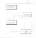
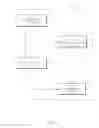


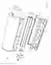
Sources:
- United States Patent and Trademark Office - verify current appl. status at the USPTO↗
Similar patent applications:
Recent applications in this class:
- » 20250162324 2025-05-22
STORAGE BAG AND PRINTING APPARATUS - » 20250162323 2025-05-22
LIQUID DISCHARGE HEAD - » 20250135786 2025-05-01
Ink-Receiving Body And Recording Method - » 20250083445 2025-03-13
FLUID EJECTION DEVICE ASSEMBLIES - » 20250065635 2025-02-27
LIQUID EJECTING APPARATUS - » 20250050646 2025-02-13
INK JET RECORDING METHOD AND INK JET RECORDING APPARATUS - » 20250050645 2025-02-13
INK CONTAINER AND RECORDING APPARATUS - » 20250050644 2025-02-13
APPARATUS FOR STORING AND/OR SUPPLYING INK TO AN INKJET PRINTHEAD - » 20250018722 2025-01-16
INK CARTRIDGE - » 20250018721 2025-01-16
INK CARTRIDGE AND INKJET RECORDING DEVICE INCLUDING INK CARTRIDGE