Vibration Proof Structure Of Fan
US20100224344A1
2010-09-09
12/397,346
2009-03-03
Abstract:
A vibration proof structure of a fan is provided. The vibration proof structure includes a frame, a plurality of buffer members, and a plurality of rigid rods. The frame is adapted for assembling with a blade assembly. The buffer members are assembled to the frame. The rigid rods are assembled inside the buffer members, respectively. Each of the rigid rods comprises an axially penetrated through hole. After the fan is secured to the object to which the fan is desired to be assembled, the vibration caused in the operation of the fan can be effectively absorbed by the buffer members, and thus the noises can be eliminated.
Interested in similar patents?
Get notified when new applications in this technology area are published.
Classification:
F04D25/0613 » CPC main
Pumping installations or systems; Units comprising pumps and their driving means the pump being electrically driven the electric motor being specially adapted for integration in the pump the electric motor being of the inside-out type, i.e. the rotor is arranged radially outside a central stator
F04D29/668 » CPC further
Details, component parts, or accessories; Combating cavitation, whirls, noise, vibration or the like ; Balancing especially adapted for elastic fluid pumps damping or preventing mechanical vibrations
H01L23/467 » CPC further
Details of semiconductor or other solid state devices; Arrangements for cooling, heating, ventilating or temperature compensation ; Temperature sensing arrangements involving the transfer of heat by flowing fluids by flowing gases, e.g. air
H01L2924/0002 » CPC further
Indexing scheme for arrangements or methods for connecting or disconnecting semiconductor or solid-state bodies as covered by; Technical content checked by a classifier Not covered by any one of groups , and
H01L2924/00 » CPC further
Indexing scheme for arrangements or methods for connecting or disconnecting semiconductor or solid-state bodies as covered by
F28F7/00 IPC
Elements not covered by group , or
Description
BACKGROUND OF THE INVENTION
1. Field of the Invention
The present invention relates generally to a fan adapted for agitating the air to generate air convection.
2. The Prior Arts
CPUs or various chips are usually main heat sources in computers or electronic equipment. A superior CPU or chip is often featured with a faster computation speed, and typically generates more heat. If the heat generated by the CPU or chip cannot be effectively dissipated out therefrom, the heat will cause a high temperature which may adversely affect or even damage the electronic component. Heat dissipation modules are widely employed in heat source contained equipments, e.g., computer hosts. When more heat sources are contained in a computer host, more heat dissipation modules are usually demanded therein.
A typical heat dissipation module usually includes heat dissipation fins, and a fan. The heat dissipation fins are usually assembled on the CPU or chip, while the fan is assembled to the fins. The heat generated by the CPU or chip can be directly conducted to the fins for achieving a large heat dissipation area thereby. The fan generates airflow to flowing over the fins for dissipating the heat out. Conventionally, the fan is usually assembled to the fins by providing a screw bolt to insert through a through hole configured at a frame of the fan, and then locking the screw bolt into a screw hole configured in the fins. The frame of the fan and the fins are all made of rigid materials, and therefore, when the fan is in operation, a resonance maybe occur which often causes noises. Specifically, current PCs have been drastically improved to achieve very high performance, thus requiring more heat dissipation modules. Accordingly, the noise may also increase, and thus should be considered to find a corresponding solution.
SUMMARY OF THE INVENTION
A primary objective of the present invention is to provide a solution for eliminating the noise caused by resonance occurred during the operation of the fan.
According to the present invention, a vibration absorptive buffer member is provided at a position where the fan is assembled with a secure member, for eliminating the noise caused by the operation of the fan.
According to an embodiment of the present invention, a secure groove is configured at a position at a periphery of a frame of the fan where the fan is predetermined to be assembled with the secure member. And the buffer member is provided in the secure groove. The buffer member is further provided with a rigid rod. The rigid rod is configured with an axially penetrated through hole for allowing the secure member to penetrate therethrough so as to secure the fan to any object to which the fan is desired to be locked. When the fan is locked to the object, the buffer member and the rigid rod are in contact with the object, while the body of the fan is not contacted with the object. Therefore, a resonance between the fan and the object can be prevented, and thus the noise is also eliminated.
According to an embodiment of the present invention, the secure groove is a dove-tail groove, and a protrusion rib having a through hole is configured in the secure groove. The frame of the fan is arranged in a mold, and an integral molding process is executed to provide a plastic soft material inside the secure groove. During the integral molding process, the plastic soft material is also fitted in the through hole of the protrusion rib for engagement. The plastic soft material is then solidified thus forming a soft buffer member.
According to an embodiment of the present invention, prior to providing the buffer member into the secure groove, the rigid rod is positioned at a suitable position of the secure groove of the frame which is arranged in the mold. When an injection molding process is executed to form the buffer member, the plastic soft material of the buffer member encloses the rigid rod, and only two ends of the rigid rod are exposed out from two sides of the buffer member, respectively, so as to allow the secure member to penetrate therethrough.
According to an embodiment of the present invention, a flection member is configured at an outer surface of the rigid rod, for achieving an improved assembly between the rigid rod and the buffer member.
BRIEF DESCRIPTION OF THE DRAWINGS
The present invention will be apparent to those skilled in the art by reading the following detailed description of a preferred embodiment thereof, with reference to the attached drawings, in which:
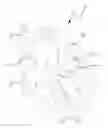
FIG. 1 is a perspective view illustrating a structural configuration of a fan according to an embodiment of the present invention;
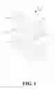
FIG. 2 is an exploded view of the fan illustrating the assembly relationship of the main elements of the fan according to an embodiment of the present invention;
FIG. 3 is a cross-sectional view of the fan when a frame of the fan is not provided with a buffer member according to an embodiment of the present invention; and
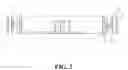
FIG. 4 is a cross-sectional view of the fan after the frame of the fan is provided with the buffer member according to an embodiment of the present invention.
DETAILED DESCRIPTION OF THE PREFERRED EMBODIMENT
The accompanying drawings are included to provide a further understanding of the invention, and are incorporated in and constitute a part of this specification. The drawings illustrate embodiments of the invention and, together with the description, serve to explain the principles of the invention.
FIG. 1 is a perspective view illustrating a structural configuration of a fan according to an embodiment of the present invention. Referring to FIG. 1, the present invention provides a vibration proof structure of a fan 1. The fan 1 includes a frame 11 made of a rigid material (e.g., aluminum alloy, or thermosetting plastic), a motor (not shown in the drawings), and a blade assembly 12 disposed in a space defined by the frame 11. The blade assembly 12 is connected with the motor. The frame 11 has four corners positioned at a periphery of the frame 11. The four corners are adapted for assembling with secure members (e.g., screw bolts or screw nuts) for securing the fan 1 to an object (e.g., fins). A soft buffer member 2 which is resilient and vibration absorptive is provided at a position of each of the corners where the fan 1 is predetermined to be assembled with the secure members. A rigid rod 3 is provided inside the buffer member 2. The rigid rod 3 is configured with an axially penetrated through hole 31 as shown in FIG. 2. The axially penetrated through hole 31 allows a rigid secure member penetrating therethrough, and then securing to the object to which the fan is desired to be locked. The buffer member 2 for example can be made of a rubber, silica gel, or any other resilient and vibration absorptive material. The four corners of the frame 11 which are adapted for assembling the secure members are configured with a height higher than the rest portion of the frame 11. In such a way, after the buffer members 2 are assembled to the four corners, and when the fan 1 is locked to the object, the body of the frame 11 remains non-contact with the object. Therefore, the vibration of the fan 1 can be effectively absorbed by the buffer member 2, thus preventing the resonance occurred between the fan 1 and the object to which the fan 1 is locked for eliminating noises.
FIG. 2 is an exploded view of the fan illustrating the assembly relationship of the main elements of the fan according to an embodiment of the present invention. FIG. 3 is a cross-sectional view of the fan when the frame of the fan is not provided with the buffer member according to an embodiment of the present invention. Referring to FIGS. 2 and 3, each of the four corners of the frame 11 is configured with a secure groove 110. Preferably, the secure groove 110 is a dove-tail groove, or any structure suitable for effectively engaging the buffer member 2 thereby. Further, a protrusion rib 111 is configured in the secure groove 110 and outwardly extending from an outer surface of the frame 11. The protrusion rib 111 is configured with a through hole 112 or an ejection rod (not shown in the drawings). A flection member 32 or a coarse surface is preferably configured at an outer surface of the rigid rod 3. The flection member 32 can be designed with a regular shape or an irregular shape.
When fabricating the vibration proof structure of the fan 1, the frame 11 and the rigid rod 3 are arranged in a mold, and a molten material, e.g., rubber, plastic, or silica gel is injected into mold cavities of the mold for configuring the buffer member 2. The molten material is filled in the secure groove 110 and encloses the protrusion rib 111 and the rigid rod 3. Meanwhile, the molten material is also filled into the through hole 112 and the flection member 32. The molten material is solidified, thus forming the buffer member 2 inside the secure groove 110. At the same time, the rigid rod 3 is also secured inside the buffer member 2, as shown in FIG. 4. In accordance with the obtained structure, the secure member 2 is allowed to penetrate the through hole 31 for locking the fan 1 to the object (e.g., the heat dissipation fins).
According to the embodiment of the present invention, the secure member is preferably a screw bolt adapted for penetrating the through hole 31 of the rigid rod 3 which is secured inside the buffer member 2 for locking the fan 1 to the object. After the fan 1 is secured to the object, the vibration caused in the operation of the fan 1 can be effectively absorbed by the buffer members 2, and thus the noises can be eliminated.
Although the present invention has been described with reference to the preferred embodiments thereof, it is apparent to those skilled in the art that a variety of modifications and changes may be made without departing from the scope of the present invention which is intended to be defined by the appended claims.
Claims
What is claimed is:1. A vibration proof structure of a fan, comprising:
a frame, adapted for assembling with a blade assembly;
a plurality of buffer members, assembled to the frame; and
a plurality of rigid rods, assembled inside the buffer members, respectively, wherein each of the rigid rods is configured with an axially penetrated through hole.
2. The vibration proof structure according to claim 1, wherein a plurality of secure grooves are configured at a periphery of the frame, and the buffer members are assembled inside the secure grooves, respectively.
3. The vibration proof structure according to claim 2, wherein the secure grooves are dove-tail grooves.
4. The vibration proof structure according claim 3, wherein the buffer members are made of a resilient material.
5. The vibration proof structure according to claim 4, wherein each of the secure grooves is configured with a protrusion rib having a through hole, and the buffer members are formed inside the secure grooves and enclosing the protrusion ribs by executing a molding process.
6. The vibration proof structure according to claim 1, wherein a flection member is configured at an outer surface of each of the rigid rods, and the flection member and the outer surface are enclosed by the buffer members.
Images & Drawings included:
Sources:
- United States Patent and Trademark Office - verify current appl. status at the USPTO↗
Recent applications in this class:
- » 20220381251 2022-12-01
PAP system blower - » 20210010480 2021-01-14
Illumination fan - » 20200248702 2020-08-06
Rotary drive for an impeller and motor assembly with gas and rolling bearings arranged in housing structure - » 20200040900 2020-02-06
Thin cooling fan - » 20190390678 2019-12-26
CENTRIFUGAL FAN - » 20190331122 2019-10-31
Illumination fan - » 20190285075 2019-09-19
Centrifugal fan comprising a sidewall and plurality of air deflectors forming a plurality of airflow entry tunnels to sequentially expand a flow channel outwardly in a radial direction - » 20180112669 2018-04-26
Dual operation centrifugal fan apparatus and methods of using same - » 20180066664 2018-03-08
THIN COOLING FAN - » 20180003183 2018-01-04
Shrouded fan impeller with reduced cover overlap