Multipurpose cartridge-based liquid dispensing air freshener system
US20100243754A1
2010-09-30
12/412,401
2009-03-27
✅ Patent granted
US 8,170,405 B2
2012-05-01
-
-
Thor Campbell
2030-09-09
Abstract:
A high-performance, modular, multipurpose, cartridge-based, liquid dispensing air freshener system that uses at least one refillable or disposable liquid filled cartridge. It can also use fixed tanks and dispense pesticides or any other liquid that can be vaporized. This programmable device can use an unlimited number of cartridges to discharge numerous different fragrances of which can be dispensed separately or mixed. A variety of chassis size and shape configurations can be used, such as a micro-sized unit that allows extreme portability so that it can be used in cars, at office desks or easily carried around in a pocket or purse; it can also function as a compact plug-in air freshener. Cartridges can be automatically selected so that the system can dispense a different scent for different time intervals or mix scents. It can be built into an automotive dash panel or designed to fit into a car style stereo slot.
Interested in similar patents?
Get notified when new applications in this technology area are published.
Classification:
A01M1/2072 » CPC main
Stationary means for catching or killing insects; Poisoning, narcotising, or burning insects; Poisoning or narcotising insects by vaporising an insecticide using a heat source combined with a fan
A01M1/2033 » CPC further
Stationary means for catching or killing insects; Poisoning, narcotising, or burning insects; Poisoning or narcotising insects by vaporising an insecticide without heating using a fan
A01M1/205 » CPC further
Stationary means for catching or killing insects; Poisoning, narcotising, or burning insects; Poisoning or narcotising insects by vaporising an insecticide without heating; Holders or dispensers for liquid insecticide, e.g. using wicks using vibrations, e.g. ultrasonic or piezoelectric atomizers
A01M1/2077 » CPC further
Stationary means for catching or killing insects; Poisoning, narcotising, or burning insects; Poisoning or narcotising insects by vaporising an insecticide using a heat source using an electrical resistance as heat source
A61L9/032 » CPC further
Disinfection, sterilisation or deodorisation of air using gaseous or vaporous substances, e.g. ozone using substances evaporated in the air by heating or combustion; Apparatus therefor comprising a fan
A61L9/035 » CPC further
Disinfection, sterilisation or deodorisation of air using gaseous or vaporous substances, e.g. ozone using substances evaporated in the air by heating or combustion; Apparatus therefor emanating multiple odours
A61L9/122 » CPC further
Disinfection, sterilisation or deodorisation of air using gaseous or vaporous substances, e.g. ozone using substances evaporated in the air without heating; Apparatus, e.g. holders, therefor comprising a fan
A61L9/125 » CPC further
Disinfection, sterilisation or deodorisation of air using gaseous or vaporous substances, e.g. ozone using substances evaporated in the air without heating; Apparatus, e.g. holders, therefor emanating multiple odours
A61L9/14 » CPC further
Disinfection, sterilisation or deodorisation of air using sprayed or atomised substances including air-liquid contact processes
B60H3/0014 » CPC further
Other air-treating devices; Adding substances other than water to the air, e.g. perfume, oxygen characterised by the location of the substance adding device
A61L2209/11 » CPC further
Aspects relating to disinfection, sterilisation or deodorisation of air; Apparatus features Apparatus for controlling air treatment
A61L2209/111 » CPC further
Aspects relating to disinfection, sterilisation or deodorisation of air; Apparatus features; Apparatus for controlling air treatment Sensor means, e.g. motion, brightness, scent, contaminant sensors
A61L2209/12 » CPC further
Aspects relating to disinfection, sterilisation or deodorisation of air; Apparatus features Lighting means
A61L2209/132 » CPC further
Aspects relating to disinfection, sterilisation or deodorisation of air; Apparatus features; Dispensing or storing means for active compounds Piezo or ultrasonic elements for dispensing
A61L2209/133 » CPC further
Aspects relating to disinfection, sterilisation or deodorisation of air; Apparatus features; Dispensing or storing means for active compounds Replaceable cartridges, refills
B60H2003/0064 » CPC further
Other air-treating devices; Adding substances other than water to the air, e.g. perfume, oxygen adding more than one substance
A61L9/04 IPC
Disinfection, sterilisation or deodorisation of air using gaseous or vaporous substances, e.g. ozone using substances evaporated in the air without heating
F24F3/14 IPC
Air-conditioning systems in which conditioned primary air is supplied from one or more central stations to distributing units in the rooms or spaces where it may receive secondary treatment; Apparatus specially designed for such systems characterised by the treatment of the air otherwise than by heating and cooling by humidification; by dehumidification
A01G13/06 IPC
Protecting plants Devices for generating heat, smoke or fog in gardens, orchards or forests, e.g. to prevent damage by frost
Description
CROSS-REFERENCE TO RELATED APPLICATIONS
Not Applicable
FEDERALLY SPONSORED RESEARCH
Not Applicable
SEQUENCE LISTING OR PROGRAM
Not Applicable
BACKGROUND OF THE INVENTION
1. Field of the Invention
The present invention relates in general to air freshener devices and more particularly to a high-performance, multipurpose cartridge-based liquid dispensing air freshener, of which can be used in many ways by using various special chassis adaptations.
2. Description of the Prior Art
There is a desire to make the ambient air more pleasing in personal living spaces, professional office settings and in motor vehicles where the atmosphere within such confined spaces contains unpleasant odors from such things as smoking, cooking and pets. Additionally, there is a desire for insect and pest control in these spaces and is an ongoing need.
It can be appreciated that air fresheners have been in use for years. Devices for producing such a scent or fragrance are well known in the prior art, and have been extensively used indoors and in vehicles. The prior art describes many of such devices that may be employed for use in these spaces for both air freshening and insect control. These devices encompass a myriad of designs by the crowded prior art that have been developed for the fulfillment of countless objectives and requirements.
The disadvantage with many air freshener devices is that the fragrance-producing material is quickly depleted or consumed whereby a strong fragrance is generated for a short time. Furthermore, some prior devices have not been refillable, and therefore in order to maintain the emission of fragrance for a long period of time, it has been necessary to replace the entire device.
Various types of dispensing devices have been devised and used in which an aerosol material is intermittently discharged as a spray into a room by either a clock mechanism that forms a part of the device or an electrically operated valve that is also included as an integral part of the dispenser. The disadvantages of these devices is that the pressurized aerosol liquid and dispensers used therewith are relatively expensive, are bulky and provide only a periodic dispensing very high concentrations of fragrance for very short bursts.
Many other prior art describe devices that provide electrical heating devices for dispensing such materials as air fresheners, deodorizers, and insect control materials. Such devices may often comprise a reservoir of liquid to be dispensed, an electric heater to warm the liquid to cause it to vaporize more readily, and an electrical plug to plug the device into an electric outlet for power. These devices have very little to no control over the fragrance output, where the device continuously works as long as it is plugged in.
While these devices fulfill their respective, particular objectives and requirements, the aforementioned patents do not disclose the unique combination of components and features of the present invention that substantially departs from the conventional concepts and designs of the prior art. Therefore, it can be appreciated that there exists a continuing need for new and improved liquid dispensing air freshener system which can be used for freshening air and/or dispensing pesticides. In this regard, the present invention substantially fulfills this need.
Various objects and advantages of the present invention, and its most novel features, will be particularly pointed out in this disclosure.
OBJECTS AND ADVANTAGES
General Objectives
It is a general object of this invention to provide a device which is able to generate an adjustable fragrance concentration over a relatively long time and which can be refilled by changing a replaceable or disposable cartridge-style container of fragrance-producing liquid or pesticide.
A still further object of the present invention is to provide a device that allows for readily replaceable cartridges which can be quickly inserted into the device for replenishment of the fragrance-enhancing material.
Another object of the present invention is to provide the ability to use more than one fragrance cartridge so that a user can select between fragrances.
Another object of the present invention is to provide a device that can quickly switch from one variety of dispensed fragrance to another with minimal mixing of the fragrances.
Another object of the present invention is to provide a device that can dispense different liquids from different cartridges at the same time and in any combination to create any desired output blend of fragrances.
Another object of the present invention is to provide a device that can dispense different liquids from a single cartridge that contains multiple chambers for different fragrances, and to dispense each liquid individually or in any combination from the cartridge.
Another object of the present invention is to provide a device that is capable of determining the type of liquid that is supplied to it and then has the ability to intelligently use this data to optimize its operation to achieve maximum performance in the vaporization and delivery of the liquid to the ambient air.
Another object of the present invention is to provide a device that has internal and/or external sensors that can measure the ambient conditions, such as temperature and humidity, in order to achieve maximum performance in the vaporization and delivery of the liquid to the ambient air.
A still further object of the present invention is to provide a device that may be retailed at a sufficiently low price as to encourage its widespread use in homes.
Multiple Use Air Freshener
Another object of the present invention is to provide an air freshener which is useable in vehicles, airplanes and buildings or in any other areas where air fresheners would be of benefit, and of which may be transported there between.
Another object of the present invention is to provide an air freshener which can be manufactured as part of a new product, such as manufacturing the device into the dash of a new car.
Another object of the present invention is to provide an air freshener which can be adapted for use with an existing product, such as an existing air-conditioning system.
Another object of the present invention is to provide a device which can be adapted to be used as a wall receptacle plug-in air freshener.
Another object of the present invention is to provide a device which can be used to dispense insect repellant or other liquid types.
Multipurpose Chassis Design
Another object of the present invention is to provide a single, multipurpose chassis that is shaped and sized to allow a single device to be used in many different ways, such as tabletop, under-counter, ceiling vent and heating/cooling duct applications.
Another object of the present invention is to provide for the use of an unlimited number of specialized chassis that are shaped and sized to allow the devices to be used in special configurations, such as automotive cigarette lighter jacks and car dash panels.
Another object of the present invention is to provide a modular chassis so that an unlimited number of fragrance cartridges can be modularly configured together into a single chassis or whereby multiple chassis can be stacked together to function as a single unit.
Another object of the present invention is to provide an extremely compact chassis option for portability so that it can be easily carried around and used anywhere, such as in a car or at an office desk.
Another object of the present invention is to provide a compact chassis in the form of a “plug-in” so that it can simply be plugged directly into a wall power outlet.
Another object of the present invention is to provide an air freshener chassis that can have multiple evaporation chambers, one for each cartridge or fragrance to allow a perfect fragrance output transition from one scent to another with very little mixing of fragrances.
Another object of the present invention is to provide a dual-purpose chassis where a user can access the device's evaporation chamber in order to add other non-cartridge based scent producing materials, such as fresh flowers, potpourri, or perfume whereby the device is used to help disperse the fragrance into the ambient air.
Multiple Methods to Vaporize and Disperse Liquid
Another object of the present invention is to provide the ability for the device to use multiple liquid types, such as highly volatile perfumes and low volatile oils, and then to provide the means to effectively vaporize them and deliver the resulting vapor into the ambient air.
Another object of the present invention is to provide the ability to use multiple methods to enhance the evaporation of its dispensed liquid, such as fans, heated elements or piezo-electric vibrators, and to use any one or all combinations of methods so that virtually any type of liquid can be readily vaporized:
-
- 1) The present invention can use a motor-driven fan which actively circulates air around the dispensed liquid to assist in the vaporization of liquid fragrance and to help expel the vapor into the ambient air;
- 2) The present invention can use a heated reservoir for the dispensed liquid fragrance whereby applied heat can readily accelerate the atomization of liquid as well as provide natural heat convection to convey the fragrance into the ambient air without the need for any moving parts;
- 3) The present invention can use a piezo-electric vibrator, that converts electrical energy into vibrational mechanical energy, such as ultrasound, that can be used to atomize liquid.
Use of Cartridges
Another object of the present invention is to provide a device whereby a user can quickly and simply swap out any desired fragrance cartridge, thus allowing a user to instantly replenish a spent cartridge or to change the cartridge selection of fragrance for variety.
Another object of the present invention is to provide the ability to use both refillable and disposable cartridges to contain liquid fragrance and/or pesticides.
Another object of the present invention is to provide the ability to use a single, multi-chamber cartridge that can contain a plurality of different fragrances.
Another object of the present invention is to provide the use of a leak-free cartridge system whereby a full or empty cartridge can be removed and reinstalled without any leakage.
Another object of the present invention is to provide a means to convey data from a cartridge about its liquid content to the dispenser's controller, such as a cartridge with an embedded chip that possess data about its contained liquid and electrical terminals that can be used to convey this data from the cartridge to the controller.
Use of Fixed Tanks
Another object of the present invention is to provide a device whereby refillable fixed tanks can be used to store liquid rather than cartridges. Large tanks would enable fewer service intervals for refilling, as would be desirable for commercial use.
Programmable Controller
Another object of the present invention is to use an electronic, programmable controller that has the ability to control all aspects of the liquid dispenser for high performance operation.
Another object of the present invention is to provide a device that is capable of determining the type of liquid that is supplied to it and then has the ability to intelligently use this data to optimize its operation to achieve maximum performance in the vaporization and delivery of the liquid to the ambient air.
Another object of the present invention is to provide the means for an electronic controller to establish communication with an embedded chip that is installed inside a cartridge for the purpose of using the data stored there for precise dispensing and vaporization control of the specific liquid contained inside the cartridge.
Another object of the present invention is to provide the means for an electronic controller to establish communication with a remote control device, for the purpose of allowing remote control of the various features of the liquid dispenser.
Multiple Power Source Capability
Another object of the present invention is to provide the ability to use multiple power sources, such as disposable or rechargeable batteries, regular household AC power, or 12/24 volt DC automotive battery power, including any combination of them.
Another object of the present invention is to provide the ability of its use with an adapter that would allow it to work in a automotive style cigarette lighter power jack.
Another object of the present invention is to provide the ability to use solar-cells to utilize the energy derived from natural sunlight or light emitted from regular room light fixture.
Special Bathroom Air Freshener
Another object of the present invention is to provide an air freshener chassis design for the bathroom so it can be inconspicuous and unobtrusive to maintain look the traditional bathroom.
Another object of the present invention is to provide a modular air freshener chassis that can be mounted onto a standard toilet's water tank and which is shaped to fit and blend in with the tank.
Summary of Objectives
The present invention accomplishes the above-stated objectives, as well as others, as may be determined by a fair reading and interpretation of the entire specification.
SUMMARY OF THE INVENTION
In the view of the foregoing disadvantages inherent in the known types of air fresheners now present in the prior art, the present invention provides an improved liquid dispensing air freshener. As such, the general purpose of the present invention, which will be described subsequently in greater detail, is to provide a new and improved liquid dispensing air freshener and method that has all the advantages of the prior art and none of the disadvantages.
It is the principal objective of the present invention to provide a multipurpose, cartridge-based liquid dispensing air freshener that can be mounted in many chassis variations in order to maximize its utility. The dispensed liquid includes perfumes, air fresheners, household cleaning materials, sanitizers, disinfectants, repellents, insecticides, aroma therapy formulations, medicinal, therapeutic liquids, or other liquids which benefit from vaporization for use.
The basic components of the present invention consists of at least one refillable or disposable cartridge that can contain liquid, at least one liquid pump, at least one liquid reservoir, an electronic controller and a specially designed chassis.
Liquid Cartridge System:
With many previous art devices, it can be inconvenient to replace the air freshener dispenser or replenish the fragrance solution. Some liquid dispensers can be very messy to refill. The present invention addresses these problems by making use of a unique removable liquid cartridge system. The present invention uses a special disposable or refillable cartridge to contain a fragrance emitting liquid. The cartridge is designed to be easily removable from its chassis, so that it can be refilled or disposed of. This cartridge also provides many advantages and options, such as:
-
- 1) Convenient Access: The replaceable cartridge can be inserted into a slot at the front of the cabinet. This position allows the user easy reach to service the unit;
- 2) Convenient Packaging Reduces Mess: The cartridge is a convenient, leak free container for liquids, allowing the user to handle it without coming in contact with the liquid inside, which can be a harsh, extremely concentrated chemical (such as insecticides).
- 3) Economical Use of Fragrances: A reusable and refillable cartridge options allows a user the ability to purchase fragrances in large quantities, such as economical gallon sized jugs. The cartridge can be simply removed from the cabinet, its cap removed and then refilled with solution;
- 4) User Choice of Fragrances: A refillable cartridge provides a user the ability to utilize any desired kind of readily available fragrance, such as a favorite perfume;
- 5) Convenience of Service: An optional disposable cartridge allows the user the convenience of simply discarding a spent cartridge. This relieves the user from the task of refilling the cartridge and from the potential of making a mess. A user has only to pull out and discard a spent cartridge and then simply insert a fresh one into the device;
- 6) Solution Level Indication: A cartridge made of a transparent or semitransparent material would allow a user to visually see the fluid level inside the cartridge simply by glancing at it, thereby allowing the user to know how much fluid remains in the cartridge. An optional electronic fluid level detector can also be used sense the level of the liquid inside the cartridge and then provide feedback for the user, whereby the controller can flash a lamp and/or signal a beeper to occasionally chirp to indicate a low fluid level condition.
The cartridge contains a unique spring-loaded drain valve that is normally closed to prevent any leakage while the cartridge is removed from the cabinet. This drain valve automatically opens once the cartridge is inserted into the air freshener chassis and closes once the cartridge is removed. This special valve system keeps the cartridge from leaking and thus allows a user to remove it at any time, even if the cartridge is completely full, without leakage. This feature also allows a user to swap out different cartridges for different fragrances, if so desired.
The cartridges can also be made so that a hollow needle can pierce the cartridge's skin to tap into the cartridge's liquid supply. Liquid will be dispensed through the hollow needle into the liquid pump. The cartridge material can be made from a resilient material such that the needle's insertion point can be self healing, so that it will not leak if the needle is removed from the cartridge.
The cartridge is designed to use an optional embedded chip that possesses data about the cartridge's liquid type for high performance purposes. Electrical terminals on the cartridge mate with contacts inside the liquid dispenser to convey this data from the cartridge to the liquid dispenser's controller. This data can also be used by the controller to determine how much liquid to dispense, when to dispense it and to more precisely vaporize the liquid. For example:
-
- 1) If a cartridge contains a scented oil that has low volatility, the controller can calculate the use of a higher reservoir heater setting and a higher fan speed to achieve a desired fragrance output concentration;
- 2) The dispenser can be programmed to use “rate of vaporization” data that is downloaded from the cartridge together with the liquid dispenser's sensors that measure the ambient conditions to ensure that the liquid has time to vaporize before dispensing more liquid. For example, if the data from the cartridge describes a liquid that is highly concentrated and volatile, the liquid dispenser can then dispense a smaller amount of the liquid at one time. After a calculated time lapse, the controller can then dispense more liquid;
The data about the cartridge's contents can also be used for display purposes. For example, if a cartridge is called “Rose Garden,” this name data can be stored in the embedded chip and downloaded to the dispenser's alphanumeric display system. This feature would work very well for remote controls.
The cartridge can also use a mechanical means to store cartridge data that can be conveyed to the controller (which can save costs). For example, the cartridge can contain a key type system where physical key ridges on the cartridge can mate with a receiving edge in the dispenser that can contain either mechanical or solid state switches to record the key's values. For instance, if the system allows for the liquid to be characterized by 16 variable states, a protruding edge on the cartridge can have 4 notches of which 16 different positions can be derived.
The cartridge can also be made to use internal bladders, whereby the cartridge would exist as a shell to encase and protect the liquid filled bladder and provide a modular structure for docking Bladders can provide several benefits:
-
- 1) As the volume of liquid is drawn out of the cartridge, air must be allowed to enter to displace the liquid (otherwise the cartridge would be crushed). Therefore a pressure relief valve is used to let air in. The use of a bladder would allow the cartridge shell to simply use ventilation holes, where air can freely circulate around the bladder as the bladder's volume is consumed;
- 2) For a special liquid mixture, it may be desired to isolate it from the ambient air until the time that it is dispensed (for example: sterile, hermetically sealed medicinal solution). A regular pressure relief valve would simply let atmospheric air into the cartridge, where it would be in contact with the liquid. Bladders can be made to be sealed and hold only liquid and no air;
- 3) Bladders would also work well in situations where the dispenser is used in inverted positions. A bladder would allow a constant flow of liquid regardless of the direction of gravity.
Multiple Liquid Cartridge System:
Many previous art devices emit only a single fragrance. A device that can emit more than one fragrance can provide for a pleasing variety. The present invention is designed to release an unlimited number of different fragrances by using multiple liquid cartridges or multiple-chamber cartridges. The liquid dispensing unit can be programmed to dispense liquid from any of the installed cartridges in any desired combination and interval.
Liquid Tank System:
One embodiment of the present invention is to accommodate the use of non-cartridge, tank style containers. A much larger tank would allow the ability for the device to hold a vast amount of liquid, which would provide a user the convenience of less frequent service refill intervals.
Liquid Pump:
The present invention uses a liquid pump assembly that is designed to pump liquid from a cartridge or liquid holding tank into an evaporation chamber. The pump assembly components couple with a cartridge once the cartridge is inserted into the air freshener chassis. The pump assembly contains an inlet orifice that automatically pushes open the cartridge's drain valve so that liquid can flow into the pump assembly. An electric pump can be energized to dispense a precise amount of fluid from the cartridge to an evaporation chamber. This liquid pump can also be used with fixed tank systems as well, instead of the cartridge.
Evaporation Chamber:
The present invention uses an evaporation chamber to vaporize any liquid that is conveyed into it. This well ventilated evaporation chamber consists of a liquid fragrance reservoir that provides a place to store liquid after it has been pumped from the cartridge. A material such as a wire mesh or sponge can be employed in the reservoir to accept and confine the dispensed liquid while time lapses during the vaporization process. This porous material has a large surface area that facilitates the evaporation of the liquid into the ambient air.
While normal evaporation of the liquid can work well with some of the present invention's chassis variations, this evaporation chamber can utilize any assisted method to help vaporize the liquid fragrance and disperse it into the ambient air, such as fans, a heated elements or piezo-electric vibrator s or any combination thereof:
-
- 1) Fan: A fan creates an airflow through the evaporation chamber, which assists the liquid to vaporize much faster and propels the fragrance from the reservoir to the ambient air. The fan can be a variable speed device so that it can operate at any desired level. A very low speed can be used for quiet, low power and mild fragrance emission. A high speed setting can be used to maximize the air freshener's output;
- 2) Heated Element: A heated element positioned below the reservoir can provide heat to the liquid to help vaporize it much faster. Natural convection from this heated element will help propel the fragrance to the ambient air. A fan can also be used with this heated element to provide maximum performance;
- 3) Piezoelectric Vibrator: A piezoelectric vibrator can also be used in the evaporation chamber. This electromechanical transducer essentially helps to atomize the fragrance in the form of fine particles or droplets.
Electronic Programmable Controller:
The present invention employs a programmable electronic device that is designed to control all of the dispenser's various features and can allow a user to select from a wide variety of pre-programmed liquid dispensing sequences. It can also be programmed for customized operation. The electronic programmable controller has the capability to:
-
- 1) Automatically power itself on and off as required;
- 2) Provide dispensing control over any installed liquid pumps to vary the liquid output volume, duration and frequency in order to provide any desired liquid output;
- 3) Automatically power an installed fan with the ability to vary its speed and consequential air throughput in very fine increments that can coincide with a calculated liquid output and vaporization rate that is optimal for the type of liquid that is being dispensed;
- 4) Select and control the output of liquid from a plurality of installed cartridges and/or from multi-chambered cartridges as well as from fixed tanks;
- 5) Select and program various operational timed intervals, such as the sequence and timing for output from any installed cartridge and daily power on/off cycles;
- 6) Indicate which cartridge is currently selected and/or operating in a multi-cartridge system;
- 7) Communicate with an embedded chip that is installed inside a cartridge for the purpose of using the data stored there to determine the type of liquid that is supplied and then intelligently use this data to optimize its operation to achieve maximum performance in the precise dispensing, vaporization and delivery of the liquid into the ambient air. This would provide the ability for the device to more efficiently use multiple liquid types, such as highly volatile perfumes and low volatile oils;
- 8) Switch the electrical polarity of an installed fan to reverse the flow of air whereby the fragranced air can be emitted behind the chassis where special ductwork can be attached to receive and discharge the fragrance to a depository;
- 9) Detect the fluid levels inside each installed cartridge and provide output indication of their fluid levels in various forms, such as a panel display or lamp;
- 10) Alert a user of a low fluid level such as visually illuminating and/or flashing a lamp or audibly chirping a beeper;
- 11) Display the type of fragrance that is contained within an installed cartridge;
- 12) Use an external switch and/or communicate with an external device to convey operational information to/from the dispenser such as: room occupancy from an external motion sensor or external equipment status, such as the startup and shutdown of an air conditioning system;
- 13) Monitor internal and external sensors to provide the dispenser with ambient conditions such as temperature and humidity so that this data can be processed to provide optimal performance;
- 14) Allow for periodic or continuous fragrance dispensing;
- 15) Dispense different liquids from different cartridges at the same time in any combination to create any desired output blend of the fragrances;
- 16) Communicate with a wired or wireless remote control device for the purpose of allowing the remote control to control the various features of the present invention.
The controller can use a display system that can allow a user better interface with the controller and can provide output data concerning the operation and performance of the device. For instance, if a cartridge is inserted into the device that is called “Spring Rose” for its rose scented fragrance, the controller download this information from the cartridge and display this name on an alphanumeric panel. Programming options for this particular cartridge can also be displayed.
Chassis Embodiments:
The present invention can be housed in many types of special chassis embodiments to allow the device to be used in a wide range of applications. Some of these chassis embodiments are listed here:
-
- 1) Modular Chassis: A modular chassis allows the present invention to expand in two ways:
- a) Separate independent chassis' can be modularly stacked and connected together to function as a single unit. For example, two “five-cartridge” liquid dispensers can be stacked together to then provide a ten-cartridge system.
- b) Modular subsections can be assembled onto a main controller body element. The modular subsections are designed to be simply snapped onto each other and then onto a controller body to form a single functioning unit, whereby an unlimited number of subsections can be added;
- 2) Dual-Purpose Chassis: The present invention can use a chassis design that provides for a dual-purpose evaporation chamber. Not only does this dual-purpose evaporation chamber have a liquid reservoir that can accept and vaporize liquid from fragrance cartridges, the chamber can also be accessed by a user for the insertion of scented objects. The fragrance from these objects can be propelled into the ambient air by the device's fan. Examples of some fragrant objects include fresh flowers, potpourri, bars of soap and perfume.
- 3) Multi-Function Chassis: The present invention can include chassis elements that allow its use in a wide variety of applications. For instance, mounting brackets can be added so that the chassis can be easily bolted onto an air conditioning duct so that fragrance can be discharged directly into the ductwork for distribution throughout a building. For another example, a duct (such as a 90 degree elbow) can be attached to the chassis so that the fragrance output can be directed down through an office building's ceiling panel, or ducted through a vent into a restroom.
- 4) Compact Wall “Plug-In” Chassis: The present invention can be constructed in a compact chassis with a built-in electrical plug so that it can function as a wall receptacle plug-in. This multi-fragrance plug-in can then be used virtually anywhere in the house or office building.
- 5) Micro Chassis: A micro-sized chassis embodiment of the present invention provides for portability. This very small air freshener can then be easily carried in a pocket or purse to be used anywhere, such as in the car or at an office desk. This tiny chassis also allows the device to be used in novel ways, such as using it in a motor vehicle's cigarette lighter power socket.
- 6) Vehicle Dash Panel Chassis: The use of perfume dispensing devices in the car is a fact that is known by everybody, with the object of creating more pleasant ambient conditions for the driver. This is due to the that unpleasant odors frequently permeate the interior of the vehicle, which emanate either from the exhaust gases or from the exterior. All this is further aggravated in the case of vehicles used by smokers in which the smell of tobacco lingers inside the car even days after the vehicle has been used. The present invention allows for a specially constructed chassis to optimize its use in motor vehicles. This compact chassis can be adaptable to fit directly into the dashboard of any motor vehicle, where it can be powered by the vehicle's electrical system and positioned to be within easy reach of the driver. This air freshener system can be added to the vehicle as an aftermarket device or as an original equipment from the vehicle's manufacturer. The air freshener can discharge fragrance directly into the vehicle and/or into the vehicle's air conditioning ductwork
- 7) Vehicle Stereo-Sized Chassis: Yet another adaptation of the present invention's chassis is to allow it to be installed into a motor vehicle's stereo panel as an aftermarket device. As most vehicles are provided with industry standard stereo panels, the present invention can make use of this area to mount an air freshener. A specially designed chassis that is sized just like a stereo system can simply be slipped into the dash panel. This chassis design can also be used wherever a standard car stereo system is used.
- 8) Toilet Tank Mounted Chassis: Air fresheners are very frequently used in bathrooms. One embodiment of the present invention is designed to take advantage of the unused space that exists above the average toilet water tank for a storage location for an air freshener. This embodiment uses a chassis assembly that consists of a unique modular cabinet housing that is designed to mount onto the top rim of a standard toilet water tank, inserted between the water tank and the water tank's lid. It is shaped to blend in with the design of the water tank for aesthetics. The bottom of the cabinet has guides that allow the cabinet to fit onto the water tank without the need for fasteners. The top edge of the cabinet housing is a rim just like that of the water tank to allow the original toilet's lid to be re-installed. This allows the stock toilet lid to be reused so that the general design of the toilet can be maintained and to help the cabinet to blend into the existing bathroom décor. The cabinet can have its own custom top as well. The general design of the cabinet is modular in nature so that a maximum of utility can be achieved. This modular design allows other modular cabinets housing assemblies to be installed above or below it.
- One important object of the present invention is to provide the most inconspicuous and unobtrusive cabinet as to maintain look the traditional bathroom. The present invention achieves this because the toilet water tank mounted modular cabinet is shaped like the water tank so as to blend in with the existing facility, making it inconspicuous. The aesthetics of the toilet then appear normal, with the appearance of only a slightly taller than usual water tank. The modular cabinet can be provided with its own detachable lid, but reusing the original stock toilet lid will better preserve the original toilet aesthetics.
- For universal applications, this modular cabinet can be offered in a generic cabinet shape or “skin” that is designed to work and look good with a wide range of brands and models of toilets. Adjustable mounting guides can assure a secure fit with a wide variety of tank shapes. This will enhance the present invention's ability to be used on large numbers of existing toilets.
- The modular cabinet's position on the water tank also allows easy installation of the device as it merely sits on the tank, requiring no fasteners. Guides on the cabinet's bottom mates with the water tank's rim to keep the cabinet securely in place. The top of the modular cabinet has a rim just like the water tank so that the original lid can be attached to it. This modular design also allows it to be easily removed so that quick service to the components inside the water tank can be made such as freeing up a stuck flush valve.
- 1) Modular Chassis: A modular chassis allows the present invention to expand in two ways:
Internal and External Sensors:
The present invention has the capability of communicating with a variety of optional internal and/or external sensors, switches or other devices to provide the controller programming and/or feedback for optimal performance. For instance, an external motion sensor can be used as an input to provide room occupancy signals. This occupancy data would allow the device to deviate from its normal programming for better efficiency. For example, if the device is normally programmed to emit fragrance in a public restroom during normal business hours, the device can deactivate if it detects no traffic, such as when the building might be closed for a holiday. Likewise, the unit can be activated if enough traffic is detected on a weekend or after business hours.
Internal and/or external sensors can also be used to measure the ambient conditions, such as temperature and humidity. This allows feedback for the electronic controller in order to achieve maximum performance for the vaporization and delivery of a liquid into the ambient air.
An optional sensor can also be used in the reservoir tray to monitor the liquid level to prevent an overflow, in which case the dispenser can be programmed to wait until enough liquid has vaporized before dispensing more liquid.
Power Supplies:
The present invention is designed to use any type of available power source in order to maximize its usefulness for any circumstance. For some examples:
-
- 1) AC/DC Power: The device can use both AC and DC power sources. Replaceable or rechargeable batteries can power the device for the situation where an AC source is unavailable. When available, an AC source can be used to power the device as well as charge the batteries;
- 2) Solar Panel: The device can use a solar panel to provide power, which would be of great benefit for a portable, micro-sized chassis that is used in a car. The solar panel can also be used to charge an optional battery;
- 2) Vehicle 12 Volt Power Jack: The device can use an adaptor so that it can tap into an automotive 12 volt power system through a standard plug-in power jack. This would allow the device plenty of power without the need for internal batteries or a solar panel.
Insecticides and Other Uses:
The present invention can be used for virtually any situation what requires the vaporization of a liquid. The dispensed liquid includes perfumes, air fresheners, household cleaning materials, sanitizers, disinfectants, repellents, insecticides, aroma therapy formulations, medicinal, therapeutic liquids, or other liquids which benefit from vaporization for use.
Summary:
Although only a few embodiments of the present invention have been described, it should be understood that the present invention may be embodied in many other specific forms without departing from the spirit or the scope of the present invention. The present examples are to be considered as illustrative and not restrictive, and the invention is not to be limited to the details given herein, but may be modified within the scope of the appended claims along with their full scope of equivalents.
The above mentioned objectives and advantages of this invention and the manner of attaining them will become more apparent and the invention itself will be best understood by reference to the following detailed descriptions of the invention taken in conjunction with the accompanying drawings.
BRIEF DESCRIPTION OF THE DRAWINGS
Various other objects, advantages, and features of the invention will become more readily apparent to those skilled in the art from the following detailed description when read in conjunction with the accompanying drawings, in which:
FIG. 1 is a front perspective view of a modular embodiment of the present invention, where an unlimited number of modules can be assembled together to form a single unit. Four modules are shown assembled onto an electronic controller to complete an air freshener assembly. A remote control is shown as an alternate means to remotely control the device.
FIG. 2 is a rear perspective view of a modular embodiment of the present invention, where an unlimited number of modules can be assembled together to form a single unit. Four modules that are shown assembled onto an electronic controller to complete an air freshener assembly. This embodiment uses individual fans that are mounted inside each modular liquid dispenser.
FIG. 3 illustrates how each air freshener module can be assembled onto the electronic controller assembly.
FIG. 4 is a rear perspective view of a modular embodiment of the present invention, where an unlimited number of modules can be assembled together to form a single unit. Four modules are shown assembled onto an electronic controller to complete an air freshener assembly. This embodiment uses a single fan that is mounted inside the modular controller.
FIG. 5 illustrates how each air freshener module can be assembled onto the modular electronic controller assembly. An aperture in each module creates a ductwork through the completed assembly to allow the use of a single fan that is mounted inside the modular controller.
FIG. 6 is a front perspective view of a single air freshener module with its top cover removed to reveal the components inside. This module uses an integral fan.
FIG. 7 is a front perspective view of a single air freshener module with an installed cartridge.
FIG. 8 is an exploded view of an air freshener module to show its parts. This module does not use an integral fan for airflow. It receives airflow through an aperture which will become part of a ductwork once all the modules are assembled onto the fan equipped controller module. A manually operated baffle is shown that would allow the module's output to be reduced, if desired to reduce fragrance mixing between modules. An embodiment of this idea would include electrically operated baffles.
FIG. 9 is a front perspective view of an embodiment of the present invention where one chassis is designed to house numerous cartridges that share a single, dual-purpose evaporation chamber. This view shows the invention with its cover hinged open to reveal five installed fragrance cartridges.
FIG. 10 is a rear perspective view of FIG. 9 to reveal a battery compartment door, power receptacle, external switch input terminals and fan intake grill.
FIG. 11 illustrates how the present invention can be adapted to fit an air conditioning duct.
FIG. 12 is a rear perspective view of the invention to demonstrate how a duct can be added to the chassis to direct the output of the device to a desired location, such as through an office ceiling panel.
FIG. 13 is a top front perspective view of the invention with its case cover removed to illustrate the components inside.
FIG. 14 is a top rear perspective view of the invention with its case cover removed to illustrate the components inside.
FIG. 15 is a top rear perspective view of an embodiment of the present invention where the output of each liquid pump is directed to a reservoir.
FIG. 16 depicts a cartridge as removed from the liquid pump assembly, where the pump assembly also functions as a mounting sleeve for a cartridge.
FIG. 17 is a front sectional view of the liquid pump assembly and cartridge mounting sleeve that illustrates the components inside.
FIG. 18 is a rear perspective view a fragrance cartridge.
FIG. 19 is a front perspective view of an embodiment of the present invention that illustrates the use of a single refillable fragrance cartridge and a dual-purpose evaporation chamber.
FIG. 20 is the same front perspective view as shown in FIG. 19 but with the cartridge and basket removed to demonstrate their removability.
FIG. 21 is a front perspective view of an embodiment of the present invention where it is installed inside a special modular case that is designed to fit onto a toilet water tank.
FIG. 22 is the same front perspective view as shown in FIG. 21 but with its front cover hinged open to reveal several installed fragrance cartridges.
FIG. 23 demonstrates an embodiment of the present invention installed onto a standard toilet's water tank.
FIG. 24 is a front perspective view of an embodiment of the present invention where a specially designed toilet tank chassis is designed to accommodate three large disposable cartridges.
FIG. 25 is a rear perspective view of an embodiment of the present invention where a specially designed toilet tank chassis is designed to accommodate three large disposable cartridges.
FIG. 26 is a front perspective view of an embodiment of the present invention where a specially designed toilet tank chassis was designed to accommodate a couple of large, fixed mounted liquid holding tanks, instead of removable cartridges.
FIG. 27 is a front perspective view of the disposable version of the liquid cartridge with a pressure relief valve located on its top side.
FIG. 28 is a front perspective view of a refillable version of the liquid cartridge that utilizes a ventilated refill cap.
FIG. 29 is a front perspective view of a liquid cartridge and liquid pump assembly to show how they would normally be mated together inside the cabinet.
FIG. 30 is a rear perspective view of a liquid cartridge and liquid pump assembly to show how they would normally be mated together inside the cabinet.
FIG. 31 is a lower rear perspective view of a liquid cartridge and liquid pump assembly with the liquid pump assembly slightly cocked from the normal alignment with the cartridge to illustrate the orientation of the mating orifices that communicate the liquid from the cartridge to the pump assembly. This view also shows the liquid level sensor on the pump assembly and its mating window pane on the cartridge.
FIG. 32 is a top front perspective view of an embodiment of the present invention that uses a portable, micro-sized chassis. A solar cell is used on its top surface as a power source.
FIG. 33 is a top rear perspective view of an embodiment of the present invention that uses a portable, micro-sized chassis. A solar cell is used on its top surface as a power source.
FIG. 34 is a front perspective view of the present invention that uses a portable, micro-sized chassis with its top cover removed to illustrate the components inside.
FIG. 35 is a top view of the present invention that uses a portable, a micro-sized chassis.
FIG. 36 is a side view of the present invention that uses a portable, a micro-sized chassis.
FIG. 37 is a front view of the present invention that uses a portable, a micro-sized chassis.
FIG. 38 is a rear view of the present invention that uses a portable, a micro-sized chassis.
FIG. 39 illustrates how a removable mounting shoe on the portable, micro-sized chassis can be used to attach it to a cigarette lighter power adapter.
FIG. 40 illustrates a hinged joint in the cigarette lighter adapter can allow the portable, micro-sized chassis to be pivoted to any desired angle.
FIG. 41 illustrates another mounting position for the removable mounting shoe on the portable, micro-sized chassis to allow a cigarette lighter power adapter to pivot it to any desired angle.
FIG. 42 illustrates how the micro-sized chassis can be hung from an eyelet.
FIG. 43 is a diagram of a compact version of the present invention as installed into an automobile's dash panel.
FIG. 44 is a diagram of the present invention as installed into an automobile's stereo area, where the air freshener chassis is specially shaped to fit into a standard stereo mounting sleeve.
FIG. 45 a front perspective view of an embodiment of the present invention where a specially designed compact, micro-chassis is shaped and configured to work as a wall receptacle plug-in, with its front cartridge access cover removed to show several installed cartridges.
FIG. 46 a front perspective view of an embodiment of the present invention where a specially designed compact, micro-chassis is shaped to work as a wall receptacle plug-in, with is front cartridge access cover installed.
FIG. 47 is a rear perspective view of an embodiment of the present invention where a specially designed compact, micro-chassis is shaped to work as a wall receptacle plug-in.
FIG. 48 a front perspective view of an embodiment of the present invention where a specially designed compact, micro-chassis is shaped to work as a wall receptacle plug-in that includes a night light that is mounted on its bottom edge.
FIG. 49 a rear perspective view of an embodiment of the present invention where a specially designed compact, micro-chassis is shaped to work as a wall receptacle plug-in that includes a night light that is mounted on its bottom edge.
FIG. 50 a front view of an embodiment of the present invention where a specially designed compact, micro-chassis is shaped to work as a wall receptacle plug-in.
FIG. 51 a front perspective view of an embodiment of the present invention where a specially designed compact, micro-chassis is shaped to work as a wall receptacle plug-in with the cartridges and fragrance outlet grill removed.
FIG. 52 is the same front perspective view as shown in FIG. 51 but now with the liquid pump assembly removed.
FIG. 53 is a functional diagram of the liquid pumping system of the wall receptacle plug-in embodiment of the present invention and how the liquid is routed to a reservoir in front of a fan.
FIG. 54 is a front perspective view of a multiple compartment cartridge.
FIG. 55 is a sectional view of a multiple compartment cartridge to illustrate its several compartments that are used to store different fragrances.
FIG. 56 is a rear perspective view of a multiple compartment cartridge to illustrate its multiple drains, where each compartment is provided with its own separate drain.
FIG. 57 is a rear perspective view of a multiple compartment cartridge to illustrate its single drain. The single drain is designed to separately dispense liquid from any of its chambers.
REFERENCE NUMERALS
- 60 Assembly, Modular Liquid Dispenser
- 61 Assembly, Modular Toilet Liquid Dispensing
- 62 Assembly, Micro Liquid Dispenser
- 63 Assembly, Wall Cartridge-based Liquid Dispenser
- 64 Assembly, Electronic Controller
- 65 Assembly, Liquid Pump & Cartridge Mounting Sleeve
- 66 Fan
- 67 Cartridge, Disposable Liquid Fragrance
- 68 Cartridge, Refillable Liquid Fragrance
- 69 Cap, Cartridge Refill
- 70 Label, Cartridge
- 71 Switch, Lighted
- 72 Button, Control
- 73 Cover, Liquid Dispenser Assembly
- 74 Grill, Fragrance Outlet
- 75 Grill, Air Inlet
- 76 Chamber, Fragrance Evaporation
- 77 Cover, Battery
- 78 Tray, Battery
- 79 Battery
- 80 Receptacle, Power
- 81 Plug, Electrical
- 82 Coupling, Duct
- 83 Duct, Exhaust
- 84 Duct, Air Inlet
- 85 Basket
- 86 Tube, Liquid Transfer
- 87 Pump, Liquid
- 88 Sensor, Liquid Level
- 89 Window, Liquid Level
- 90 Drain, Cartridge
- 91 Valve, Drain
- 92 Seal, O-Ring
- 93 Orifice, Pump Inlet
- 94 Actuator, Valve
- 95 Compartment, Cartridge
- 96 Vent, Pressure Release
- 97 Panel, Solar
- 98 Slot, Cartridge Mounting
- 99 Panel, Switch Programming
- 100 Light, Night
- 101 Reservoir
- 102 Tank, Toilet Water
- 103 Guide, Mounting
- 104 Tank, Fixed—Refillable
- 105 Tray, Fragrance Evaporation Reservoir
- 106 Assembly, Modular Controller
- 107 Pin, Mounting
- 108 Cartridge, Multi-Compartment—Single Drain
- 109 Cord, Hanging
- 110 Cartridge, Multi-Compartment and Multi-Drain
- 111 Shoe, Mounting
- 112 Adapter, Cigarette Lighter Power
- 113 Mount, Eyelet
- 114 Joint, Hinged Cigarette Lighter Power Adapter
- 115 Duct, Air Conditioning
- 116 Panel, Car Dash
- 117 Terminals, External Switch Input
- 118 Sensor, Occupancy
- 119 Contact, Cartridge Electrical Data Path
- 120 U.S. Penny
- 121 Sleeve, Stereo Style Mounting (DIN)
- 122 Assembly, Car Air Freshener Stereo Replacement Chassis
- 123 Assembly, Car Dash Internally Mounted Chassis
- 124 Baffle
- 125 Assembly, Liquid Pump
- 126 Assembly, Liquid Dispenser
- 127 Aperture
- 128 Guide, Cartridge Alignment and Support
- 129 Lid, Water Tank
- 130 Control, Wireless Remote
- 131 Fitting, Liquid Tube
DETAILED DESCRIPTION OF THE DRAWINGS
As required, detailed embodiments of the present invention are disclosed herein; however, it is to be understood that the disclosed embodiments are merely exemplary of the invention which may be embodied in various forms. Therefore, specific structural and functional details disclosed herein are not to be interpreted as limiting, but merely as a basis for the claims and as a representative basis for teaching one skilled in the art to variously employ the present invention in virtually any appropriately detailed structure.
Various other objects, advantages, and features of the invention will become more readily apparent to those skilled in the art from the following detailed description when read in conjunction with the accompanying drawings, in which like reference numerals designate like parts throughout the figures thereof.
Modular Liquid Dispensing Air Freshener:
FIGS. 1-6 illustrate the modular nature of the present invention, where an unlimited number of cartridge-based liquid dispensing modules can be assembled together to form a single unit. This unique design allows only one or any combination of installed dispensers to be activated.
FIG. 1 is a front perspective view of a modular embodiment of the present invention, where four modular liquid dispenser assemblies 60 are shown assembled onto a modular controller assembly 106 to complete a single modular air freshener unit. Each modular liquid dispenser assembly 60 has its own fragrance outlet grill 74, liquid fragrance cartridge 67 and a lighted switch 71. A lighted switch 71 allows a user to select (or deselect) the assembly 60 for operation and illuminates to indicate its operational status.
FIG. 1 also illustrates wireless remote control 130 that can be used with the present invention in order to remotely control the device. A wired remote control can also be used. This feature allows the present invention to be mounted in remote places, such as in a ceiling or air conditioner closet, yet allow a user to have a more convenient location for a controller. For example, if the present invention is mounted onto an air conditioner duct, a dual-purpose remote control can program and control both the air conditioner and the liquid dispensing air freshener. The remote control 130 can be equipped with a digital display for easy programming and for device status.
The controller assembly 106 is also capable of determining the type of liquid that is supplied to it and then has the ability to intelligently use this data to optimize its operation to achieve maximum performance in the vaporization and delivery of the liquid to the ambient air. Thus, the cartridges 67 are designed to contain an element that describes the contents of its cartridge, such as data that is programmed into an embedded chip. The controller assembly 106 is designed to establish communication with this embedded chip in an installed cartridge and convey this data to the controller for the precise dispensing and vaporization control of the specific liquid contained inside the cartridge.
FIG. 2 is a rear perspective view of a modular embodiment of the present invention, where four modular liquid dispenser assemblies 60 are shown assembled onto a modular controller assembly 106 to complete a single unit. Each modular liquid dispenser assembly 60 has its own fan and air inlet grill 75, and a fragrance reservoir tray 105.
Power is supplied to the unit by plugging a standard electrical cord into the power receptacle 80. Remote switch input terminals 117 can be used to provide feedback to the liquid dispenser for such things as remote occupancy detectors or control signals from an air conditioning system.
FIG. 3 illustrates how numerous modular liquid dispenser assemblies 60 can be assembled onto a modular controller assembly 106. The mounting pins 107 double function as electrical connectors to provide each assembly 60 with power and programming data from the modular controller assembly 106.
FIG. 4 is a rear perspective view of a modular embodiment of the present invention, where four modular liquid dispenser assemblies 60 are shown assembled onto a modular controller assembly 106 to complete a single unit. This embodiment uses a single fan that is mounted inside the modular controller assembly 106 to circulate air from an air let 75 into each dispenser assembly 60.
FIG. 5 illustrates how numerous modular liquid dispenser assemblies 60 can be assembled onto a modular controller assembly 106. This embodiment uses a single fan that is mounted inside the modular controller assembly 106 to draw air in from an air let 75 and propel the air through each dispenser assembly 60 through their apertures 127 and exhaust from the fragrance outlet grills 74. The mounting pins 107 double function as electrical connectors to provide each assembly 60 with power and programming data from the modular controller assembly 106.
FIG. 6 is a front perspective view of a single modular liquid dispenser assembly 60 with its top cover removed to reveal the components inside. This embodiment of the liquid dispenser assembly 60 has its own dedicated fan 66. The liquid pump and cartridge mounting sleeve assembly 65 dispenses a liquid fragrance from a cartridge 67 and deposits it to a reservoir 101. The fan 66 pulls air into the assembly 60 which passes over the reservoir 101 to vaporize and deliver fragrance out of the assembly 60 through a fragrance outlet grill 74. The reservoir 101 is mounted into a reservoir tray 105 so that it can be withdrawn from the assembly 60 for cleaning
FIG. 7 is a front perspective view of a single modular liquid dispenser assembly 60 with an installed fragrance cartridge 67. This embodiment of the liquid dispenser assembly 60 has an aperture 127 to allow airflow into the device. The mounting pins 107 double function as electrical connectors to provide each assembly 60 with power and programming data. A lighted switch 71 allows a user to select (or deselect) the assembly 60 for operation and illuminates to indicate its operational status. An optional baffle 124 can be used to restrict airflow through an assembly 106 to prevent undesired mixing of different fragrances from other dispenser assemblies 106.
FIG. 8 is an exploded view of a single modular liquid dispenser assembly 60 to show its parts. This embodiment of the liquid dispenser assembly 60 has an aperture 127 to allow airflow into the device. The liquid pump and cartridge mounting sleeve assembly 65 dispenses a liquid fragrance from a cartridge 67 and deposits it to a reservoir 101. Air enters the assembly 60 through an aperture 127 which passes over the reservoir 101 to vaporize and deliver fragrance out of the assembly 60 through a fragrance outlet grill 74. The reservoir 101 is mounted into a reservoir tray 105 so that it can be withdrawn from the assembly 60 for cleaning An optional baffle 124 can be used to restrict airflow through an assembly 60 to prevent undesired mixing of different fragrances from other dispenser assemblies 60. An embodiment of this mechanical baffle 124 idea would involve electrically operated baffles.
Liquid Dispensing Air Freshener:
FIGS. 9-20 illustrate the present invention's liquid dispensing system that is mounted into a single chassis that can accommodate multiple cartridges.
FIG. 9 is a front perspective view of an embodiment of the liquid dispenser assembly 126 where a single chassis is designed to house numerous fragrance cartridges 67 that share a single, dual-purpose evaporation chamber 76. The dual-purpose evaporation chamber 76 not only functions to evaporate liquid fragrance that is dispensed from the cartridges 67 into its reservoir 101 but can also be used to accept any fragrance producing material that can be placed into the basket 85 such as fresh flowers, potpourri, or perfume whereby the liquid dispenser system is then used to help disperse the fragrance into the ambient air. This view shows the invention with its cover 73 hinged open to reveal several installed fragrance cartridges 67. The electronic controller assembly 64 can be programmed to dispense liquid fragrance from any one or combination of any installed cartridges 67. The liquid fragrance is dispensed into a reservoir 101 in the evaporation chamber 76 where a fan 66 evaporates the liquid fragrance and exhausts it through outlet grill 74 into the ambient air. A lighted switch 71 allows a user to select (or deselect) the assembly 126 for operation and illuminates to indicate its operational status.
FIG. 10 is a rear perspective view of an embodiment of the liquid dispenser assembly 126 where a single chassis is designed to house numerous fragrance cartridges. This view reveals a battery compartment door 77, power receptacle 80 and air inlet grill 75. This dispenser assembly 126 offers dual power capability of electricity or batteries.
FIG. 11 illustrates how the present invention can be adapted to fit an air conditioning duct 115. Remote switch terminals 117 (shown in FIG. 12) can be used to allow the liquid dispenser assembly 126 to start and stop in concert with an air conditioning system to automatically supply fragrance to the air while the air conditioner is operational.
FIG. 12 is a rear perspective view of the liquid dispenser assembly 126 to demonstrate how a duct 83 can be added to the chassis using a duct coupler 82 to direct the fragrance output of the device to a desired area. For example, the assembly 126 can be mounted in the ceiling area of office building and its output directed through the duct 83 and down through a ceiling panel into office space. The fan inside the assembly 126 can be programmed to reverse direction for this purpose.
FIG. 13 is a top front perspective view of the liquid dispenser assembly 126 with its case cover removed to illustrate the components inside. For more clarity, a battery 79 is shown removed from its normal location in the battery tray 78.
FIG. 14 is a rear perspective view of the liquid dispenser assembly 126 with its case cover removed to illustrate the components inside. For more clarity, a battery 79 is shown removed from its normal location in the battery tray 78.
FIG. 15 is a side perspective view of an embodiment of the present invention where the output of each liquid pump assembly 65 is directed to a single reservoir 101 using liquid transfer tubes 86. A very thin layer of metal mesh in this reservoir 101 can absorb and confine the liquid so that it does not flow from the reservoir if the air freshener chassis is tilted. The metal mesh is very porous to allow maximum air movement for evaporation. This reservoir 101 can also contain a heated element to help vaporize any liquid that is deposited there. The heat can be readily transmitted into the metal mesh from the heated element for maximum efficiency.
FIG. 16 depicts a disposable liquid fragrance cartridge 67 as removed from the liquid pump and cartridge mounting sleeve assembly 65. The cartridge 67 contains a label 70 that specifies its contents.
FIG. 17 is a side sectional view of the liquid pump assembly and cartridge mounting sleeve assembly 65 that illustrates the components inside. Its basic shape contains a cavity that functions as a mounting sleeve to help align and mount a cartridge.
FIG. 18 is a rear perspective view a liquid fragrance cartridge 67. The cartridge 67 contains a label 70 that specifies its contents.
FIG. 17 and FIG. 18 also shows an electronic liquid level sensor 88 on the assembly 65 and a liquid level window pane 89 on the cartridge 67. The pane 89 normally rests within very close proximity to the level sensor 88. The window pane 89 portion of the cartridge 67 is made of a transparent material so that the sensor 88 can detect the level of the fluid inside the cartridge 67. The level sensor 88 communicates with the control module assembly 64 (shown in FIG. 13) so that the fluid level can be known and displayed. The control module assembly 64 can flash a lamp or provide a periodic audible beep to signal a low fluid level condition.
FIG. 17 and FIG. 18 also illustrates the orientation of the mating orifices that communicate the liquid from the cartridge to the pump assembly. The cartridge drain 90 mates with the pump inlet orifice 93. Valve actuator 94 opens the drain valve 91 inside the drain 90 to allow liquid to flow from the cartridge 67 to the pump assembly 65.
FIG. 17 and FIG. 18 also illustrates contacts 119 in assembly 65 that establishes electrical connectivity with mating contacts 119 on the cartridge 67. This feature allows data that is embedded inside the cartridge to be conveyed to the control module assembly 64 (shown in FIG. 13).
FIG. 19 is a front perspective view of an embodiment of the liquid dispenser assembly 126 that illustrates the use of a single refillable fragrance cartridge 68 and a dual-purpose evaporation chamber 76.
FIG. 20 is the same front perspective view as shown in FIG. 19 but with the cartridge 68 and basket 85 removed to demonstrate their removability. A cartridge alignment and support guide 128 keeps the cartridge 68 aligned and supported within the assembly 126 so that it can properly mate with the liquid pump assembly that is mounted at the back of the guide 128.
Toilet Mounted Modular Chassis:
FIG. 21-31 illustrates an embodiment the present invention that is formed when a liquid dispenser assembly is mounted in a special modular chassis that is designed to mount onto a standard toilet's water tank.
FIG. 21 is a front perspective view of an embodiment of the present invention where a liquid dispenser assembly 126 is installed inside a special toilet modular chassis assembly 61 that is designed to fit onto a toilet water tank. An air inlet duct 84 provides airflow to the dispenser assembly 126. Fragrance is emitted from the fragrance outlet grill 74.
FIG. 22 is the same front perspective view as shown in FIG. 21 but with its front cover hinged open to reveal several installed fragrance cartridges 67.
FIG. 23 illustrates the basic idea of an embodiment of the present invention where the modular liquid dispenser cabinet assembly 126 is installed inside a special toilet modular chassis 61 and shown mounted onto a standard toilet's water tank 102. The modular chassis 61 is shaped to match the design of the water tank 102 so that it helps blend in with the toilet and décor of the bathroom. The stock water tank lid 129 can be installed onto the modular chassis 61 to help maintain the stock look of the toilet, or a custom tank lid can be used. The modular chassis 61 can also have an integral, non-removable top as well.
FIG. 24 is a front perspective view of an embodiment of the present invention where a specially designed toilet tank chassis 61 is designed to accommodate three large disposable cartridges 67. This embodiment also can use a dual-purpose evaporation chamber 76.
FIG. 25 is a rear perspective view of an embodiment of the present invention where a specially designed toilet tank chassis 61 is designed to accommodate three large disposable cartridges 67.
FIG. 26 is front perspective view of an embodiment of the present invention where a specially designed toilet tank chassis 61 was designed to accommodate a couple of large, fixed mounted liquid holding tanks 104, instead of removable cartridges. These larger tanks 104 can be permanently fixed inside the chassis 61 or can be made to be removable like the cartridge version.
FIG. 27 is a front perspective view of a disposable version of the liquid fragrance cartridge 67. A pressure relief valve 96 allows the flow of air into the cartridge 67 as its solution is consumed. A label 70 is shown affixed to the front of the cartridge 67 to identify its contents.
Another variation of the cartridge shown in FIG. 27 is to use a bladder system, whereby the bladder would reside inside the protective shell of the cartridge. There are some benefits to using a bladder system since liquid can be drawn from it at any angle, without the use of gravity. A pressure relieve valve would not be required. As the bladder's contains is depleted, its size will diminish. The cartridge shell only needs to have perforations to allow air to enter.
FIG. 28 is a front perspective view of a refillable version of the liquid cartridge 68 shown with its refill cap 69. However, this refillable cartridge 68 can also be disposable. The refill cap 69 can be removed and more solution added. The refill cap 69 is ventilated, which allows the flow of air into the cartridge 68 as its solution is consumed. A label 70 is shown affixed to the front of the cartridge 68 to identify its contents.
FIG. 29 is a side perspective view of a liquid cartridge 68 and liquid pump assembly 125 to show how they would normally be mated together inside a chassis.
FIG. 30 is a rear perspective view of a liquid cartridge 68 and liquid pump assembly 125 to show how they would normally be mated together inside a chassis. A label 70 can be affixed to the cartridge 68 to identify its contents.
FIG. 31 is a perspective view of a liquid cartridge 67 and liquid pump assembly 125 with the liquid pump assembly 125 slightly cocked from the normal alignment with the cartridge 67 to illustrate the orientation of the mating orifices that communicate the liquid from the cartridge 67 to the pump assembly 125. The disposable cartridge 67 (or refillable cartridge 68) can be removed at any time, where a spring loaded drain valve 91 located inside its cartridge drain 90 closes whenever it is pulled away from the pump assembly 125. An “O-ring” type seal 92 around the drain 90 seals against the pump inlet orifice 93. Once the cartridge 67 becomes mated with the pump assembly 125, a valve actuator 94 inside the pump inlet orifice 93 pushes open the drain valve 91 in the cartridge drain 90 to allow liquid to flow from the cartridge 67 into the pump assembly 125.
FIG. 31 also shows an electronic liquid level sensor 88 on the pump assembly 125 and a liquid level window pane 89 on the cartridge 67. The pane 89 normally rests within very close proximity to the level sensor 88. The window pane 89 portion of the cartridge 67 is made of a transparent material so that the sensor 88 can detect the level of the fluid inside the cartridge 67. The level sensor 88 communicates with a control module 64 (shown if FIG. 26) so that the fluid level can be known and displayed. The control module 64 can flash a lamp or provide a periodic audible beep to signal a low fluid level condition.
Yet another method can be used to dispense liquid from the cartridge other than that the method illustrated in FIG. 31. A hollow pin can pierce the cartridge's shell as the cartridge is inserted into the dispenser. Liquid can then be drawn through the pin. The cartridge's shell can be made of a self healing material that can allow for the pin hole to be sealed once the pin is extracted to prevent leaks.
Micro-Sized Liquid Dispensing Air Freshener:
FIG. 32-44 illustrates the embodiments of the present invention where the basic system is mounted into compact, micro-sized chassis that are designed to be extremely portable. These compact chassis are especially designed to work well in automobiles.
FIG. 32 is a front perspective view of an embodiment of the present invention that uses a portable, micro-sized chassis. This micro liquid dispenser assembly 62 can accept at least one cartridge 67. An optional solar panel 97 is shown on the dispenser assembly 62 as a power source.
FIG. 33 is a rear perspective view of an embodiment of the present invention that uses a portable, micro-sized chassis. This micro liquid dispenser assembly 62 can accept at least one cartridge 67. An optional solar panel 97 is shown on the dispenser assembly 62 as a power source.
FIG. 34 is a front perspective view of the portable, micro liquid dispenser assembly 62 with its top cover removed to illustrate the components inside. A battery 79 provides power for the dispenser assembly 62. A rechargeable battery can also be used, where a solar panel 97 (shown in FIG. 33) can keep it charged. Liquid pump 125 dispenses liquid from the cartridge 67 into the reservoir 101 that is located inside the evaporation chamber 76. A fan 66 will push air over the reservoir 101 to evaporate the liquid and propel fragrance through the outlet grill 74. Switch 72 allows for control and selection of programmed functions. A penny 120 is shown next to the assembly 62 as a scale reference to emphasize the tiny size of the device.
FIG. 35 is a top view of the micro liquid dispenser assembly 62 that uses a portable, a micro-sized chassis. Solar panel 97 is used to supply power. Fragrance can also be propelled through the top outlet grill 74.
FIG. 36 is a side view of the micro liquid dispenser assembly 62 that uses a portable, a micro-sized chassis.
FIG. 37 is a front view of the micro liquid dispenser assembly 62 that uses a portable, a micro-sized chassis.
FIG. 38 is a rear view of the micro liquid dispenser assembly 62 that uses a portable, a micro-sized chassis.
FIG. 39 illustrates how a removable mounting shoe 111 on a micro liquid dispenser assembly 62 can be used to attach it to a cigarette lighter power adapter 112.
FIG. 40 illustrates a hinged joint 114 in the cigarette lighter adapter 112 can allow a micro liquid dispenser assembly 62 to be pivoted to any desired angle.
FIG. 41 illustrates another mounting position for the removable mounting shoe 111 on a micro liquid dispenser assembly 62 to allow a cigarette lighter power adapter 112 to pivot it to any desired angle.
FIG. 42 illustrates how micro liquid dispenser assembly 62 can be hung from an eyelet 113 by using a cord 109.
FIG. 43 is a diagram of car dash mounted chassis assembly 123 can be designed to fit into an automobile's dash panel 116. This embodiment of the present invention is shown with a front outlet grill 74. It can also be made to discharge fragrance directly into the car's air conditioning ductwork so that the fragrance can be more evenly distributed though the vehicle.
FIG. 44 is a diagram of an embodiment of the present invention where the liquid dispenser system's chassis is specially shaped into a car air freshener stereo replacement chassis 122. This specially shaped chassis will fit into a standard stereo mounting sleeve 121 so that it can be quickly and easily installed into the stereo area of an automobile's dash panel 116. This unique air freshener embodiment can be used anywhere a standard stereo system is used.
Micro-Sized Plug-In Liquid Dispensing Air Freshener:
FIG. 45-53 illustrate an embodiment of the present invention that uses a compact, micro-sized wall receptacle plug-in chassis. This compact chassis allows the air freshener to be plugged into any standard power receptacle.
FIG. 45 a front perspective view of an embodiment of the present invention where a specially designed compact, micro-chassis is shaped and configured to work as a wall receptacle plug-in. This wall cartridge-based liquid dispenser assembly 63 is shown with its front cartridge access cover removed to show several installed cartridges 67. Fragrance is emitted from the fragrance outlet grill 74. Lighted switches 71 allows a user to select (or deselect) the assembly 63 for operation and illuminates to indicate its operational status.
FIG. 46 a front perspective view of an embodiment of the present invention where a specially designed compact, micro-chassis is shaped and configured to work as a wall receptacle plug-in. This wall cartridge-based liquid dispenser assembly 63 is shown with its front assembly cover 73 installed. Fragrance is emitted from the fragrance outlet grill 74. Lighted switches 71 allows a user to select (or deselect) the assembly 63 for operation and illuminates to indicate its operational status.
FIG. 47 is a rear perspective view of an embodiment of the present invention where a specially designed compact, micro-chassis is shaped and configured to work as a wall receptacle plug-in. This wall cartridge-based liquid dispenser assembly 63 is shown with electrical plug 81 that provides power to the unit and supports its chassis in a standard wall receptacle. Air is drawn into the assembly 63 though the air inlet 75.
FIG. 48 a front perspective view of an embodiment of the present invention where a specially designed compact, micro-chassis is shaped and configured to work as a wall receptacle plug-in that includes a night light 100 that is mounted on its bottom edge. This wall cartridge-based liquid dispenser assembly 63 is shown with its front assembly cover 73 installed. Fragrance is emitted from the fragrance outlet grill 74. Lighted switches 71 allows a user to select (or deselect) the assembly 63 for operation and illuminates to indicate its operational status.
FIG. 49 a rear perspective view of an embodiment of the present invention where a specially designed compact, micro-chassis is shaped and configured to work as a wall receptacle plug-in that includes a night light 100 that is mounted on its bottom edge. This wall cartridge-based liquid dispenser assembly 63 is shown with electrical plug 81 that provides power to the unit and supports its chassis in a standard wall receptacle. Air is drawn into the assembly 63 though the air inlet 75. A switch programming panel 99 allows a user the capability to program the device. A more sophisticated control panel with an alphanumerical display can also be used to simplify programming effort.
FIG. 50 is a front view of an embodiment of the present invention where a specially designed compact, micro-chassis is shaped and configured to work as a wall receptacle plug-in. This wall cartridge-based liquid dispenser assembly 63. Fragrance is emitted from the fragrance outlet grill 74. Lighted switches 71 allows a user to select (or deselect) the assembly 63 for operation and illuminates to indicate its operational status.
FIG. 51 is the same front perspective view as shown in FIG. 45, but now the wall cartridge-based liquid dispenser assembly 63 has its cartridges 67 and fragrance outlet grill 74 removed to illustrate the components inside.
FIG. 52 is the same front perspective view as shown in FIG. 51 but now the wall cartridge-based liquid dispenser assembly 63 has its liquid pump assembly 125 removed to illustrate the components inside.
FIG. 53 is a functional diagram of the liquid pumping system of the wall receptacle plug-in embodiment of the present invention and how the liquid is routed. Liquid pumps 87 operate to pump liquid from cartridges 67 into liquid transfer tubes 86 through the pumps 87 and finally on into a liquid reservoir 101 that is positioned in front of a fan 66.
Multiple Chamber Cartridges:
FIG. 54 is a front perspective view of a multiple compartment cartridge 110. This cartridge 110 has three separate compartments, each of which can store a different fragrance. A single cartridge with multiple fragrances can offer a user more convenience without having to handle multiple cartridges.
FIG. 55 is a sectional view of a multiple compartment cartridge 110 to illustrate its several compartments 95 that are used to store different fragrances.
FIG. 56 is a rear perspective view of a multiple compartment cartridge 110 to illustrate its multiple drains 90, where each of the compartments is provided with its own drain 90.
FIG. 57 is a rear perspective view of a multiple compartment cartridge 108 to illustrate its single drain 90. This single drain 90 can have multiple ports, where solution can be drawn from any of the desired compartments. The cartridge 108 can also have a method to internally switch a single port drain 90 with any of the compartments.
Claims
What is claimed is:1) A multipurpose, cartridge-based liquid dispensing vaporization system that can automatically dispense at least one type of liquid into various specially designed chassis', comprising:
a) a chassis that is sized and shaped for a plurality of mounting configurations and uses;
b) a power supply;
c) at least one liquid pump;
d) at least one removable cartridge or tank that can contain liquid;
e) a means for conveying liquid from said cartridge to said liquid pump when said cartridge is joined with said liquid pump;
f) a means to control the activation of said liquid dispensing system;
g) at least one reservoir to contain any dispensed liquid from said pump;
h) a means to vaporize said liquid from said reservoir into the ambient air;
i) whereby a liquid channel is established between said cartridge and said liquid pump when said cartridge is joined with said liquid pump;
j) whereby said liquid pump can activate as necessary to dispense liquid from said cartridge to said reservoir where a means can allow the vaporization of said liquid from said reservoir into the ambient air;
2) The invention of claim 1 whereby a means for conveying liquid from said cartridge to said liquid pump when said cartridge is joined with said liquid pump is a valve mechanism, comprising:
a) a cartridge drain deposed on said cartridge to allow liquid to flow from said cartridge, comprising:
i) a liquid drain valve that can open to release liquid from said cartridge drain;
ii) a tensioned mechanism on said drain valve to keep said drain valve normally closed while said cartridge is removed from said liquid pump;
iii) whereby said drain valve can be opened to allow liquid flow, and closed to prevent liquid flow from said cartridge drain;
b) a liquid inlet orifice deposed in said liquid pump to provide the flow of liquid from said cartridge into said liquid pump, comprising:
i) a valve actuator deposed on said inlet orifice of said liquid pump that is positioned to engage said drain valve in said cartridge when said cartridge is joined with said liquid pump to automatically open said drain valve;
c) whereby said drain valve in said cartridge can be automatically opened or closed upon joining or separating said cartridge from said liquid pump;
d) whereby liquid contained in said cartridge can be conveyed into said liquid pump once said cartridge is joined with said liquid pump;
3) The invention of claim 1 whereby a means for conveying liquid from said cartridge to said liquid pump when said cartridge is joined with said liquid pump consists of a hollow pin that protrudes from said liquid pump that can penetrate the shell of said cartridge as said cartridge is inserted into said dispenser and whereby the cartridge shell's material can be made to be self-healing for leak control once said pin is extracted from said cartridge once said cartridge is removed from said dispenser;
4) The invention of claim 1 whereby said means to control the activation of said liquid dispensing system is an electronic apparatus, comprising:
a) electronic circuits that have inputs and outputs and programmed circuit logic to control said dispensing system;
b) means for controlling at least one said liquid pump to dispense a specified output volume of liquid for any duration or interval;
c) optional means for controlling more than one said liquid pump, whereby each said liquid pump can be independently controlled to dispense a specified output volume of liquid for any duration or interval;
d) an optional display for programming and status indication;
e) optional lamps and buzzers for system device status;
f) optional switches for selecting preprogrammed functions and for programming;
g) whereby said electronic apparatus can control the activation of said liquid dispensing system with one or any number of installed liquid pumps and provide optional user interface enhancements;
5) The invention of claim 1 whereby said chassis can be modularly stacked together to form a single functioning unit, or can be formed from an assembly of modular subcomponents, comprising:
a) a control module, comprising:
i) a power supply;
ii) a means to control the activation of said liquid dispensing system;
b) at least one liquid dispensing module, comprising:
i) at least one removable cartridge or tank that can contain liquid;
ii) at least one liquid pump;
iii) a means for conveying liquid from said cartridge to said liquid pump when said cartridge is joined with said liquid pump;
iv) at least one reservoir to contain any dispensed liquid from said pump;
v) a means to vaporize said liquid from said reservoir into the ambient air;
vi) whereby a liquid channel is established between said cartridge and said liquid pump when said cartridge is joined with said liquid pump;
vii) whereby said liquid pump can dispense liquid from said cartridge to said reservoir where a means can allow the vaporization of said liquid from said reservoir into the ambient air;
c) a module attachment method, comprising:
i) fasteners that can allow an unlimited number of said liquid dispensing modules to be securely assembled together onto said control module;
ii) a method to interconnect electrical conductors between said liquid dispensing modules that allow each module to have power and communication with said control module;
iii) whereby any of number of said liquid dispensing modules can be securely assembled together and also have power and communication with said control module;
d) whereby any of number of said liquid dispensing modules can be securely assembled together onto said control module which provides power and communication;
e) whereby said liquid pump can activate as necessary to dispense liquid from said cartridge to said reservoir where a means can allow the vaporization of said liquid from said reservoir into the ambient air;
6) The invention of claim 1 whereby said chassis is constructed to function as a dual-purpose device such that a user can access the chassis' liquid reservoir compartment or an evaporation chamber in order to place non-cartridge dispensed scent producing materials, such as fresh flowers, potpourri or perfume, whereby said dual-purpose device is used to disperse said scent producing materials into the ambient air;
7) The invention of claim 1 whereby said chassis can be made very compact for portability so that it can be carried in a pocket or purse and used anywhere such as in motor vehicles and at the office;
8) The invention of claim 1 whereby said chassis is made very compact with a built-in electric plug so that it can function as an electric wall receptacle “plug-in” device that can also include an illumination panel for a night light feature;
9) The invention of claim 1 whereby said chassis is designed to attach onto the rim of a toilet water tank and can be shaped to fit and blend in with said water tank;
10) The invention of claim 1 whereby said chassis is dimensioned according to popular car stereo sizes to allow said liquid dispensing system to be mounted wherever standard stereos or stereo receptacles can be used;
11) The invention of claim 1 whereby a plurality of cartridges and liquid pumps can be used to dispense a plurality of liquid types;
12) The invention of claim 1 whereby said system has the means to dispense liquid from any of its liquid sources in a sequence or concurrently in any interval to achieve any one or combination of vapor mixture compositions;
13) The invention of claim 1 whereby said chassis can contain a single liquid reservoir located inside an evaporation chamber, or can contain a plurality of reservoirs and evaporation chambers;
14) The invention of claim 1 whereby said cartridge can be refillable and reusable, or can be non-refillable and disposable;
15) The invention of claim 1 whereby said liquid dispensing system uses a single or plurality of fixed-mounted tanks to store dispensing liquid instead of removable cartridges;
16) The invention of claim 1 whereby said cartridge contains a plurality of chambers for the purpose of storing different kinds of liquids and contains the means to dispense said liquids without mixing them;
17) The invention of claim 1 whereby said cartridge can use an internal bladder to store liquid therein, where said cartridge would form a protective shell for said bladder and provide a modular structure for its use in said liquid dispensing system;
18) The invention of claim 1 whereby said cartridge contains an embedded electronic component or mechanical means for storing relevant data specification about the liquid that is confined within said cartridge and has a means to convey this data to said controller that is external to the cartridge, and whereby said controller can retrieve relevant data from said cartridge and use said data to enhance the performance of said liquid dispensing vaporization system;
19) The invention of claim 1 whereby a means to vaporize said liquid from said reservoir into the ambient air uses normal liquid evaporation and convection, and/or uses other techniques to enhance liquid vaporization such as fans, heated elements and piezo-electric transducers or any combination thereof;
20) The invention of claim 1 whereby said system can use internal and/or external sensors, switches and devices to provide data to enhance the system's operational performance, such as temperature and humidity sensors to measure ambient conditions, occupancy sensors and air conditioner machine status;
21) The invention of claim 1 whereby any of its components in part or in total is manufactured in combination with a new product such as the dash panel of an automobile, an air conditioning system or toilet;
22) The invention of claim 1 whereby said liquid used in said multipurpose liquid dispensing vaporization system includes perfumes, air fresheners, household cleaning materials, sanitizers, disinfectants, repellents, insecticides, aroma therapy formulations, medicinal, therapeutic liquids, or other liquids which benefit from vaporization for use;
23) The invention of claim 1 whereby said dispensing system uses a remote control, such as a wired or wireless device, in order to remotely control the various features of said dispensing system.
Images & Drawings included:
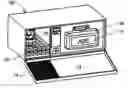
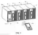
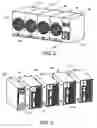
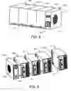

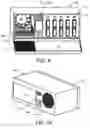
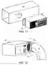
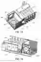
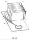


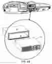


Sources:
- United States Patent and Trademark Office - verify current appl. status at the USPTO↗
Recent applications in this class:
- » 20250017191 2025-01-16
THERMAL FOGGER METHOD AND SYSTEM FOR CREATING STABLE AEROSOLS - » 20210259233 2021-08-26
FOGGER MACHINE - » 20190029245 2019-01-31
BASE CHAMBER AND COVER WITH DIFFUSER FOR REPELLENT REFILL USE IN A FAN - » 20160044908 2016-02-18
Packaged terminal climate unit for pest control - » 20140215901 2014-08-07
Bed Bug Control Devices, Systems and Methods Using Heat and Volatile Insecticides - » 20120304528 2012-12-06
Packaged terminal climate unit for pest control - » 20090162253 2009-06-25
Volatile material diffuser and method of preventing undesirable mixing of volatile materials - » 20080178518 2008-07-31
Apparatus to better distribute an insect repellant or fragrance