Sliding Mechanism
US20100244643A1
2010-09-30
12/413,808
2009-03-30
Abstract:
A sliding mechanism includes a fixed member and a movable member. The fixed member has a first end provided with a first stop member and a second end provided with two second stop members. The movable member has a first end provided with two first limit members and a second end provided with a second limit member. The two first limit members protrude outwardly from the first end of the fixed member when the movable member is movable forward, and the second limit member protrudes outwardly from the second end of the fixed member when the movable member is movable backward, so that the two opposite ends of the movable member are movable to protrude outwardly from the two opposite ends of the fixed member so as to increase the movement distance of the sliding mechanism.
Interested in similar patents?
Get notified when new applications in this technology area are published.
Classification:
A47B88/57 » CPC main
Drawers for tables, cabinets or like furniture; Guides for drawers; Safety devices or the like for drawers preventing complete withdrawal of the drawer
A47B88/483 » CPC further
Drawers for tables, cabinets or like furniture; Guides for drawers; Sliding drawers; Slides or guides therefor with single extensible guides or parts
A47B2210/0018 » CPC further
General construction of drawers, guides and guide devices; Guide construction for drawers Buffers, stop blocks or latches for single drawer slides
Description
BACKGROUND OF THE INVENTION
1. Field of the Invention
The present invention relates to a sliding mechanism and, more particularly, to a sliding mechanism for a drawer and the like.
2. Description of the Related Art
A conventional sliding mechanism comprises a fixed member and a movable member movably mounted on the fixed member. The fixed member has a front end provided with a front stop rib and a rear end provided with a rear stop rib. The movable member has a rear end provided with a limit rib that is movable to abut the front stop rib or the rear stop rib of the fixed member to limit the movable member on the fixed member. However, the movable member can protrude outwardly the front end of the fixed member and cannot protrude outwardly the rear end of the fixed member, thereby shortening the distance of movement of the sliding mechanism.
BRIEF SUMMARY OF THE INVENTION
In accordance with the present invention, there is provided a sliding mechanism, comprising a fixed member and a movable member movably mounted on the fixed member. The fixed member has a first end provided with a first stop member and a second end provided with two second stop members spaced from each other. The movable member has a first end provided with two first limit members spaced from each other and a second end provided with a second limit member.
The primary objective of the present invention is to provide a sliding mechanism having a greater distance of movement.
Another objective of the present invention is to provide a sliding mechanism, wherein the two first limit members on the first end of the movable member protrude outwardly from the first end of the fixed member when the movable member is movable forward relative to the fixed member, and the second limit member on the second end of the movable member protrudes outwardly from the second end of the fixed member when the movable member is movable backward relative to the fixed member, so that the two opposite ends of the movable member are movable to protrude outwardly from the two opposite ends of the fixed member so as to increase the movement distance of the sliding mechanism.
A further objective of the present invention is to provide a sliding mechanism, wherein the movable member is movable relative to the fixed member in two opposite directions so as to increase the movement distance of the sliding mechanism, so that the material of the sliding mechanism can be reduced so as to decrease the costs of fabrication.
Further benefits and advantages of the present invention will become apparent after a careful reading of the detailed description with appropriate reference to the accompanying drawings.
BRIEF DESCRIPTION OF THE SEVERAL VIEWS OF THE DRAWING(S)
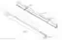
FIG. 1 is a perspective view of a sliding mechanism in accordance with the preferred embodiment of the present invention.
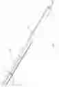
FIG. 2 is an exploded perspective view of the sliding mechanism as shown in FIG. 1.
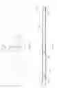
FIG. 3 is a locally enlarged view of a movable member of the sliding mechanism as shown in FIG. 2.
FIG. 4 is a front cross-sectional view of the sliding mechanism as shown in FIG. 1.
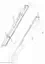
FIG. 5 is a schematic operational view of the sliding mechanism as shown in FIG. 1.
FIG. 6 is a front cross-sectional view of the sliding mechanism as shown in FIG. 5.
DETAILED DESCRIPTION OF THE INVENTION
Referring to the drawings and initially to FIGS. 1-4, a sliding mechanism in accordance with the preferred embodiment of the present invention comprises a fixed member 10 and a movable member 20 movably mounted on the fixed member 10.
The fixed member 10 has a first end provided with a first stop member 11 and a second end provided with two second stop members 12 spaced from each other. The second end of the fixed member 10 has a gap 13 defined between the two second stop members 12. The first stop member 11 of the fixed member 10 faces and aligns with the gap 13 of the fixed member 10. The first stop member 11 of the fixed member 10 is located at a height between the two second stop members 12.
The movable member 20 has a first end provided with two first limit members 21 spaced from each other and a second end provided with a second limit member 22. The first end of the movable member 20 has a spacing 23 defined between the two first limit members 21. The second limit member 22 of the movable member 20 faces and aligns with the spacing 23 of the movable member 20 and also faces and aligns with the gap 13 of the fixed member 10. The second limit member 22 of the movable member 20 is located at a height that is between the two first limit members 21 and is equal to that of the first stop member 11 of the fixed member 10. The two first limit members 21 of the movable member 20 face and align with the two second stop members 12 of the fixed member 10 respectively. The spacing 23 of the movable member 20 faces and aligns with the first stop member 11 of the fixed member 10.
When in use, the second limit member 22 of the movable member 20 is movable to pass through the gap 13 of the fixed member 10 and is movable to abut the first stop member 11 of the fixed member 10 as shown in FIG. 4. At the same time, the two first limit members 21 of the movable member 20 protrude outwardly from the fixed member 10 when the second limit member 22 of the movable member 20 is movable to abut the first stop member 11 of the fixed member 10. In addition, the two first limit members 21 of the movable member 20 are movable to allow the first stop member 11 of the fixed member 10 to pass through the spacing 23 of the movable member 20 and are movable to abut the two second stop members 12 of the fixed member 10 as shown in FIG. 6. At the same time, the second limit member 22 of the movable member 20 protrudes outwardly from the fixed member 10 when the two first limit members 21 of the movable member 20 are movable to abut the two second stop members 12 of the fixed member 10.
In operation, referring to FIGS. 4-6 with reference to FIGS. 1-3, when the movable member 20 is movable forward relative to the fixed member 10 as shown in FIG. 1, the second limit member 22 of the movable member 20 is movable to pass through the gap 13 of the fixed member 10 and is movable to abut the first stop member 11 of the fixed member 10 as shown in FIG. 4 to stop movement of the movable member 20. On the contrary, when the movable member 20 is movable backward relative to the fixed member 10 as shown in FIG. 5, the two first limit members 21 of the movable member 20 are movable to allow the first stop member 11 of the fixed member 10 to pass through the spacing 23 of the movable member 20 and are movable to abut the two second stop members 12 of the fixed member 10 as shown in FIG. 6. In such a manner, the two opposite ends of the movable member 20 are movable relative to the fixed member 10 to protrude outwardly from two opposite ends of the fixed member 10 so as to increase the movement distance of the sliding mechanism.
Accordingly, the two first limit members 21 on the first end of the movable member 20 protrude outwardly from the first end of the fixed member 10 when the movable member 20 is movable forward relative to the fixed member 10, and the second limit member 22 on the second end of the movable member 20 protrudes outwardly from the second end of the fixed member 10 when the movable member 20 is movable backward relative to the fixed member 10, so that the two opposite ends of the movable member 20 are movable to protrude outwardly from the two opposite ends of the fixed member 10 so as to increase the movement distance of the sliding mechanism. In addition, the movable member 20 is movable relative to the fixed member 10 in two opposite directions so as to increase the movement distance of the sliding mechanism, so that the material of the sliding mechanism can be reduced so as to decrease the costs of fabrication.
Although the invention has been explained in relation to its preferred embodiment(s) as mentioned above, it is to be understood that many other possible modifications and variations can be made without departing from the scope of the present invention. It is, therefore, contemplated that the appended claim or claims will cover such modifications and variations that fall within the true scope of the invention.
Claims
1. A sliding mechanism, comprising:
a fixed member;
a movable member movably mounted on the fixed member;
wherein the fixed member has a first end provided with a first stop member and a second end provided with two second stop members spaced from each other;
the movable member has a first end provided with two first limit members spaced from each other and a second end provided with a second limit member.
2. The sliding mechanism of claim 1, wherein
the second end of the fixed member has a gap defined between the two second stop members;
the first end of the movable member has a spacing defined between the two first limit members.
3. The sliding mechanism of claim 2, wherein the first stop member of the fixed member faces and aligns with the gap of the fixed member.
4. The sliding mechanism of claim 1, wherein the first stop member of the fixed member is located at a height between the two second stop members.
5. The sliding mechanism of claim 2, wherein the second limit member of the movable member faces and aligns with the spacing of the movable member.
6. The sliding mechanism of claim 2, wherein the second limit member of the movable member faces and aligns with the gap of the fixed member.
7. The sliding mechanism of claim 1, wherein the second limit member of the movable member is located at a height that is between the two first limit members.
8. The sliding mechanism of claim 1, wherein the second limit member of the movable member is located at a height that is equal to that of the first stop member of the fixed member.
9. The sliding mechanism of claim 1, wherein the two first limit members of the movable member face and align with the two second stop members of the fixed member respectively.
10. The sliding mechanism of claim 2, wherein the spacing of the movable member faces and aligns with the first stop member of the fixed member.
11. The sliding mechanism of claim 2, wherein the second limit member of the movable member is movable to pass through the gap of the fixed member.
12. The sliding mechanism of claim 1, wherein the second limit member of the movable member is movable to abut the first stop member of the fixed member.
13. The sliding mechanism of claim 12, wherein the two first limit members of the movable member protrude outwardly from the fixed member when the second limit member of the movable member is movable to abut the first stop member of the fixed member.
14. The sliding mechanism of claim 12, wherein the two first limit members of the movable member are movable to allow the first stop member of the fixed member to pass through the spacing of the movable member.
15. The sliding mechanism of claim 1, wherein the two first limit members of the movable member are movable to abut the two second stop members of the fixed member.
16. The sliding mechanism of claim 15, wherein the second limit member of the movable member protrudes outwardly from the fixed member when the two first limit members of the movable member are movable to abut the two second stop members of the fixed member.
17. The sliding mechanism of claim 1, wherein the first and second ends of the movable member are movable relative to the fixed member to protrude outwardly from the first and second ends of the fixed member.
Images & Drawings included:
Sources:
- United States Patent and Trademark Office - verify current appl. status at the USPTO↗
Similar patent applications:
- » 20090131127
Slide mechanism and slide-type electronic device having the slide mechanism - » 20150072906
Sliding mechanism and grease composition for sliding mechanisms - » 20080102908
Sliding Mechanism and Portable Communication Device Utilized the Sliding Mechanism - » 20070186481
Automatic forward movement mechanism, sliding door mechanism, and drawer mechanism - » 20130141874
SLIDING MECHANISM FOR SLIDING A DISPLAY MODULE RELATIVE TO A HOST MODULE AND PORTABLE ELECTRONIC DEVICE THEREWITH - » 20240260742
Automatically lockable pivoting mechanism and sliding mechanism, and frame and table having same - » 20220354245
Automatically lockable pivoting mechanism and sliding mechanism, and frame and table having same - » 20110135225
Sliding mechanism and sliding device - » 20070097607
Sliding mechanism with variable sliding range thereof - » 20080005867
Sliding mechanism for slide-type portable electronic device
Recent applications in this class:
- » 20240065438 2024-02-29
Slide rail assembly and slide rail kit - » 20240023708 2024-01-25
Storage device with drawer retainer and stabilizer - » 20220338628 2022-10-27
Storage device with drawer retainer and stabilizer - » 20220240673 2022-08-04
Slide rail assembly - » 20210361068 2021-11-25
Guiding apparatus - » 20210076820 2021-03-18
Shelf system for service vehicles in particular and associated container - » 20210022499 2021-01-28
Storage device with drawer retainer and stabilizer - » 20200214445 2020-07-09
DRAWER SLIDE ASSEMBLY - » 20200128961 2020-04-30
Drawer rail and home appliance including the same - » 20190098997 2019-04-04
Mechanism to prevent sliding for cabinet drawers