Part of composite material having a wedge between two zones
US20100247903A1
2010-09-30
12/478,251
2009-06-04
✅ Patent granted
US 8,277,938 B2
2012-10-02
-
-
David Sample | Nathan Van Sell
2030-07-31
Abstract:
A part (5) of composite material having a wedge (13) between two zones (11, 15), the second zone (15) being shorter than the first zone (11), whose structure comprises from its outer surface (21) to its inner surface (23): a first section (31) formed from at least two continuous sheets (41) extending parallel to its outer surface (21), the gradient of the wedge (13) being between 20% and 50%; a wedge (33) in the shape of a triangular prism with its larger surface (27) dimensioned in such a way that it forms a wedge having a gradient of less than 20%; a second section (35) formed by a plurality of continuous sheets (45) extending parallel to the surface bounded by the said first section (31) with the said wedge (33) placed upon it. The invention also relates to a process for manufacture of the part (5).
Inventors:
- José Orencio Granado Macarrilla 7 🇪🇸 Madrid, Spain
- Vicente Martínez Valdegrama 10 🇪🇸 Madrid, Spain
- Vicente Martínez Valdegrama 5 🇪🇸 Alpedrete, Spain
- José Orencio Granado Macarrilla 3 🇪🇸 Torrejon de la Calzada, Spain
- Jose Luis Lozano Garcia 9 🇪🇸 Getafe, Spain
- Jose Luis Lozano Garcia 8 🇪🇸 Madrid, Spain
Assignee:
- AIRBUS OPERATIONS SL 154 🇪🇸 Madrid, Spain
- AIRBUS ESPANA S.L. 7 🇪🇸 Getafe, Spain
Interested in similar patents?
Get notified when new applications in this technology area are published.
Classification:
B64C1/00 IPC
Fuselages; Constructional features common to fuselages, wings, stabilising surfaces and the like
B64C1/00 IPC
Aircraft structures or fairings
B29C70/865 » CPC main
Shaping composites, i.e. plastics material comprising reinforcements, fillers or preformed parts, e.g. inserts by incorporating or moulding on preformed parts, e.g. inserts or layers, e.g. foam blocks; Incorporated in coherent impregnated reinforcing layers, e.g. by winding completely encapsulated
B32B1/00 » CPC further
Layered products having a general shape other than plane
B32B3/28 » CPC further
Layered products comprising a layer with external or internal discontinuities or unevennesses, or a layer of non-planar form ; Layered products having particular features of form characterised by a particular shape of the outline of the cross-section of a continuous layer; characterised by a layer with cavities or internal voids ; characterised by an apertured layer characterised by a layer comprising a deformed thin sheet, i.e. the layer having its entire thickness deformed out of the plane , e.g. corrugated, crumpled
B32B5/26 » CPC further
Layered products characterised by the non- homogeneity or physical structure, i.e. comprising a fibrous, filamentary, particulate or foam layer; Layered products characterised by having a layer differing constitutionally or physically in different parts characterised by the presence of two or more layers which are next to each other and are fibrous, filamentary, formed of particles or foamed one layer being a fibrous or filamentary layer another layer also being fibrous or filamentary
B29C70/386 » CPC further
Shaping composites, i.e. plastics material comprising reinforcements, fillers or preformed parts, e.g. inserts comprising reinforcements only, e.g. self-reinforcing plastics; Shaping operations therefor; Shaping by lay-up, i.e. applying fibres, tape or broadsheet on a mould, former or core; Shaping by spray-up, i.e. spraying of fibres on a mould, former or core; Automated lay-up, e.g. using robots, laying filaments according to predetermined patterns Automated tape laying [ATL]
B29L2031/7738 » CPC further
Other particular articles; Articles characterised by their shape and not otherwise provided for Wedge shaped
B32B2605/18 » CPC further
Vehicles Aircraft
Y02T50/40 » CPC further
Aeronautics or air transport Weight reduction
Y02T50/40 » CPC further
Aeronautics or air transport Weight reduction
Y10T156/10 » CPC further
Adhesive bonding and miscellaneous chemical manufacture Methods of surface bonding and/or assembly therefor
Y10T156/1075 » CPC further
Adhesive bonding and miscellaneous chemical manufacture; Methods of surface bonding and/or assembly therefor with cutting, punching, tearing or severing; Prior to assembly of plural laminae from single stock and assembling to each other or to additional lamina
Y10T428/12486 » CPC further
Stock material or miscellaneous articles; All metal or with adjacent metals Laterally noncoextensive components [e.g., embedded, etc.]
Y10T428/12493 » CPC further
Stock material or miscellaneous articles; All metal or with adjacent metals Composite; i.e., plural, adjacent, spatially distinct metal components [e.g., layers, joint, etc.]
Y10T428/24479 » CPC further
Stock material or miscellaneous articles; Structurally defined web or sheet [e.g., overall dimension, etc.] including variation in thickness
Y10T428/249923 » CPC further
Stock material or miscellaneous articles; Web or sheet containing structurally defined element or component Including interlaminar mechanical fastener
Y10T428/26 » CPC further
Stock material or miscellaneous articles Web or sheet containing structurally defined element or component, the element or component having a specified physical dimension
B32B37/10 IPC
Methods or apparatus for laminating, e.g. by curing or by ultrasonic bonding characterised by the pressing technique, e.g. using action of vacuum or fluid pressure
G11B11/105 IPC
Recording on or reproducing from the same record carrier wherein for these two operations the methods are covered by different main groups of groups - or by different subgroups of group ; Record carriers therefor using recording by magnetic means or other means for magnetisation or demagnetisation of a record carrier, e.g. light induced spin magnetisation; Demagnetisation by thermal or stress means in the presence or not of an orienting magnetic field using a beam of light or a magnetic field for recording and a beam of light for reproducing, e.g. light-induced thermomagnetic recording, Kerr effect reproducing
B32B3/00 IPC
Layered products comprising a layer with external or internal discontinuities or unevennesses, or a layer of non-planar form ; Layered products having particular features of form
B32B7/08 IPC
Layered products characterised by the relation between layers; Layered products characterised by the relative orientation of features between layers, or by the relative values of a measurable parameter between layers, i.e. products comprising layers having different physical, chemical or physicochemical properties; Layered products characterised by the interconnection of layers; Interconnection of layers by mechanical means
B32B15/06 IPC
Layered products comprising a layer of metal comprising metal as the main or only constituent of a layer, next to another layer of a of natural rubber or synthetic rubber
B32B15/08 IPC
Layered products comprising a layer of metal comprising metal as the main or only constituent of a layer, next to another layer of a of synthetic resin
B64C30/00 IPC
Supersonic-type aircraft
B64C1/10 IPC
Fuselages; Constructional features common to fuselages, wings, stabilising surfaces and the like; Frames; Stringers; Longerons ; Fuselage sections Bulkheads
B64C3/00 IPC
Wings
B64C5/00 IPC
Stabilising surfaces
B64D7/00 IPC
Arrangements of military equipment, e.g. armaments, armament accessories, or military shielding, in aircraft; Adaptations of armament mountings for aircraft
B64B1/02 IPC
Lighter-than-air aircraft Non-rigid airships
B29C65/00 IPC
Joining of preformed parts ; Apparatus therefor
Description
FIELD OF THE INVENTION
This invention relates to the structure of the lay-up of a part of composite material having a wedge between two zones which is manufactured by curing the said lay-up in an autoclave, and more particularly the structure of the lay-up of a part of composite material for an aircraft structure.
BACKGROUND TO THE INVENTION
Processes for the manufacture of parts which basically comprise a first stage of laying-up sheets by means of ATL “Automatic Tape Lay-Up” and a second stage of curing in an autoclave are well-known in the aviation industry.
During the lay-up stage layers of composite material such as a prepreg, which is a storable mixture of fibre reinforcement and polymer matrix, are placed in a mould/tool of suitable shape.
This material may be in various forms and in particular in the form of a sheet. In the case of thermo-hardening matrices the resin is generally partly cured or brought to a controlled viscosity, known as the B-stage, by another process.
Sheets of composite material are not located randomly but are positioned in each zone in a number and having an orientation of their fibre reinforcement, typically carbon fibre, which are determined according to the nature and magnitude of the forces which the part must withstand in each zone. ATL (“Automatic Tape Lay-Up”) machines are generally used for this.
Automatic tape lay-up machines are very efficient for manufacturing flat or substantially flat lay-ups given that the permissible gradients for such machines are small.
Nevertheless there are aircraft structures which include wedges which, although it would be desirable from the design point of view that they should have gradients greater than those permissible for ATL machines, are finally designed with smaller gradients in order to comply with the manufacturing constraints of these machines. This gives rise to various disadvantages which this invention is intended to overcome.
SUMMARY OF THE INVENTION
One object of this invention is to provide a lay-up structure of a part made of composite material whose configuration includes a wedgebetween two zones and which can be manufactured using an ATL machine even though the gradient of the wedge is greater than that required for the use of this type of machine.
Another object of this invention is to provide a lay-up structure for a part made of composite material whose configuration includes a wedgebetween two zones which makes manufacture using an ATL machine easier without changes in the configuration of the wedgewhich involve increases in weight.
Another object of this invention is to provide a lay-up structure for a part made of composite material whose configuration includes a wedge between two zones which makes it easier to manufacture using an ATL machine without changes in the configuration of the wedgeproviding connection between the part and additional elements.
In a first aspect of these and other objects are accomplished by means of a part manufactured from a lay-up of layers of composite material which includes a wedgebetween a first zone and a second zone, generally of shorter length than the first zone, whose structure comprises from its outside surface to its inside surface:
-
- a first section formed from at least two continuous sheets extending parallel to the outer surface of the part where the gradient of the outer surface of the wedgeis between 20% and 50%.
- a wedge in the shape of a triangular prism placed on the said first section and with its largest surface dimensioned in such a way that it forms a wedgehaving a gradient of less than 20% ending at the start of the said second zone,
- a second section formed of a plurality of continuous sheets extending parallel to the surface bounded by the said first section with the said wedge placed upon it.
In a preferred embodiment of this invention the gradient of the outer surface of the wedgeis between 20% and 35% and the gradient of the largest surface of the wedge is less than 15%. By this means a lay-up structure which can be used for most parts of composite material for aircraft structures designed with wedgescan be achieved.
In a preferred embodiment of this invention the gradient of the outer surface of the wedgeis between 20% and 35% and the gradient of the largest surface of the wedge is less than 15%. By this means a lay-up structure which can be used for most parts of composite material designed with wedgescan be achieved.
In another preferred embodiment of this invention, the said wedge is made of a composite material which is cured in the same cycle as the part. Manufacture is facilitated by this means.
In a second aspect there is provided a process for manufacture of the part mentioned which comprises laying up sheets of composite material on a lay-up tool having the shape of the outer surface of the part and curing in an appropriate device through which:
-
- in a first stage the sheets of the first section are laid-up using an ATL machine and compacted manually,
- in a second stage the wedge is positioned,
- in a third stage the sheets of the second section are laid-up and compacted using an ATL machine.
Other features and advantages of this invention will be apparent from the following detailed description of an illustrative embodiment of the object of the invention in relation to the appended figures.
DESCRIPTION OF THE FIGURES
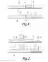
FIG. 1 is a diagrammatical view in cross-section of a part of composite material having a wedgebetween two zones, the upper part of which illustrates the structure which is desirable from the design point of view and the lower part of which illustrates the structure used to adapt to the constraints required by the use of an ATL machine during the stage of laying-up the part.
FIG. 2 is a diagrammatical view in cross-section of the same part in FIG. 1 with some stiffening elements to illustrate one of the problems arising in the known art with parts incorporatingwedges.
FIG. 3a is a view of a horizontal tailplane of an aircraft with a torsion box in which the lining is a part having a wedgebetween two zones and FIG. 3b is a partial detailed view of an area of attachment of a component of the trailing edge.
FIG. 4 is a diagrammatical view in transverse cross-section of the structure of a part having a wedgebetween two zones according to this invention.
FIGS. 5a, 5b and 5c are diagrammatical views of the process of laying-up a part having a wedgebetween two zones according to this invention.
DETAILED DESCRIPTION OF THE INVENTION
This invention relates to parts manufactured from composite material having a wedgelike the parts 3, 3′ illustrated in FIGS. 1 and 2 having a wedge 13 between two zones 11, 15. These figures also show a part 7, of smaller thickness than parts 3, 3′, which has to be joined to them in zone 15, with its outer surface in line with that of zone 11.
As an example of parts of this type in the aviation industry, mention may be made of the linings of the torsion boxes of tailplanes illustrated in FIGS. 3a and 3b in which zone 11 in parts 3, 3′ corresponds to the lining 5 of the box proper and zone 15 corresponds to the connecting edge 7 of components 9 of the leading edge and trailing edge which in turn correspond to part 7. Wedges 13, 13′ are determined by the difference in thickness between part 7 and parts 3, 3′ so that the outer surface of zone 11 of parts 3, 3′ and the outer surface of part 7 have appropriate aerodynamic continuity.
Parts 3 and 3′ in FIGS. 1 and 2 show the structure which is desirable from the design point of view and the structure which can be manufactured using the known art respectively.
In the situation illustrated in FIG. 1 it will be seen that one problem arising from part 3′, whose structure includes a portion 13′ which is more gently wedged than wedge 13 in part 3, which has a greater gradient, is the increase in weight corresponding to shaded area 19.
In the situation illustrated in FIG. 2 it will be seen that the problem arising as a result of part 3′, whose structure includes a wedge 13′ having a gentler gradient than wedge 13 of part 3, which has a larger gradient, is the problem that the location of the final part of zone 15 is in conflict with T-shaped stiffening member 17 attached to part 7, apart from the same problem of increased weight as in the previous situation, and the problem that the extension of the wedge towards zone 15 of part 3′ makes it difficult to fit machined panels or covers to its inner surface, as it is difficult to do this on inclined surfaces.
It follows from the above that it would be desirable to be able to manufacture parts of composite material having wedges which have a gradient greater than that required for an ATL machine on their outer surfaces in order to avoid the abovementioned disadvantages.
According to this invention this is overcome through a part 5 having a wedge 13 between two zones 11, 15 in which the gradient of outer surface 25 of the wedgeis between 20% and 50%, depending upon the design requirements, and whose structure comprises, as shown in FIG. 4:
-
- a first section 31 formed of a reduced number of sheets extending parallel to outer surface 21 of part 5,
- a wedge 33 in the shape of a triangular prism placed on the said first section 31 whose largest surface 27 forms a wedgehaving a gradient of less than 20% and ends at the start of the second zone 15 of part 5,
- a second section 35 formed of a plurality of continuous sheets extending parallel to the surface bounded by the said first section 31 with the said wedge 33 placed upon it.
As may be seen in FIG. 4, the two smaller surfaces of wedge 33 bound a broken surface parallel to that of outer surface 21 of part 5 and its larger surface 27 has a gradient compatible with the requirements of the lay-up machine in order that it should operate correctly. Thus its function is to convert the very inclined gradient of surface 25 of the wedge into the gentler gradient of the surface 27 of wedge 33 in order to assist laying-up of the sheets for second section 35 using an ATL machine. In addition to this it will be seen that inner surface 23 of part 5 is an optimal surface for the fitting of members which must be supported upon it.
Preferably wedge 33 is made using a roving of carbon fibre which is cured in the same cycle as the part. In other embodiments wedge 33 may be made of materials such as for example glass fibre.
In another preferred embodiment of this invention the gradient of outer surface 25 of the wedgeis between 20% and 35% and the gradient of the largest surface of wedge 33 is less than 15%.
By following FIGS. 5a, 5b, 5c, the three basic stages which follow each other in the laying-up of part 5 will be seen:
-
- in the first stage sheets 41 of section 31 which follow the external geometry of part 5 and lay-up wedge 39 are laid up. The sheets may be laid-up using an ATL machine, but must be compacted manually because the machine cannot do this correctly, given the gradient of the wedge,
- in the second stage wedge 33 is fitted. The location of wedge 33 on the inside of part 5 avoids problems of surface finish and cracking which would occur if it was located on the outside of part 5,
- in the third stage the sheets 45 of section 35 are laid-up using an ATL machine in the normal way.
Those modifications which are included within the scope defined by the following claims may be introduced into the preferred embodiments which have just been described.
Claims
1. A part (5) manufactured by the laying-up of sheets of composite material which includes a wedge (13) between a first zone (11) and a second zone (15) characterised in that its structure comprises from its outer surface (21) to its inner surface (23):
a first section (31) formed of at least two continuous sheets (41) extending parallel to the outer surface (21) of the part (5), the gradient of the outer surface (25) of the wedge (13) being between 20% and 50%,
a wedge (33) in the shape of a triangular prism placed on the said first section (31) with its larger surface (27) dimensioned in such a way that it forms a wedge having a gradient of less than 20% ending at the start of the said second zone (15),
a second section (35) formed by a plurality of continuous sheets (45) extending parallel to the surface bounded by the said first section (31) with the said wedge (33) placed upon it.
2. A part (5) according to claim 1, characterised in that the gradient of the outer surface (25) of the wedge (13) is between 20% and 35% and the gradient of the larger surface (27) of the wedge (33) is less than 15%.
3. A part (5) according to either of claims 1-2, characterised in that the said wedge (33) is made of a composite material which is cured in the same cycle as the part (5).
4. A part (5) according to any one of claims 1-3, characterised in that it forms part of the lining of a torsion box of an aircraft tailplane.
5. A process for the manufacture of a part (5) according to any one of claims 1-4, which comprises laying-up the sheets of composite material on a lay-up tool (39) having the shape of the outer surface of the part (5) and curing it in a suitable device, characterised in that:
a) in a first stage the sheets (41) of the first section (31) are laid-up using an ATL machine and compacted manually,
b) in a second stage the wedge (33) is fitted,
c) in a third stage the sheets (45) of the second section (35) are laid-up and compacted using an ATL machine.
Images & Drawings included:


Sources:
- United States Patent and Trademark Office - verify current appl. status at the USPTO↗
Recent applications in this class:
- » 20230294374 2023-09-21
METHOD FOR MANUFACTURING POLYMER COMPOSITES WITH EMBEDDED FUNCTIONALITIES - » 20230182419 2023-06-15
TOOL DEVICE FOR MANUFACTURING A RIM, AND RIM, AND USE - » 20230119338 2023-04-20
ALTERNATIVE PRIMER APPLICATION METHOD - » 20210213692 2021-07-15
Co-molding of non-crimped fabric and SMC - » 20200384710 2020-12-10
PROCESS FOR MANUFACTURING A COMPOSITE PANEL - » 20200215774 2020-07-09
Moldless vacuum infusion process - » 20190160765 2019-05-30
Casing of reinforced composite material, and a method of fabricating it - » 20180200970 2018-07-19
Method and Apparatus for Encapsulating Tubing with Material Having Engineered Weakened Portions - » 20170334155 2017-11-23
Production of a plurality of different fiber composite components for high volumes in a continuous process - » 20160167319 2016-06-16
Thread Manufacture for Filament Wound Mandrel
Recent applications for this Assignee:
- » 20230364867 2023-11-16
Device and method for manufacturing composite parts for an aircraft bulkhead - » 20230094636 2023-03-30
Carbon nanotubes reinforced bipolar plate - » 20220341311 2022-10-27
Device and method for drilling with automatic drilling parameters adaptation - » 20220185495 2022-06-16
Aircraft and method of operating an aircraft comprising an air separation device - » 20220040936 2022-02-10
Sandwich panel with a honeycomb core and method for manufacturing thereof - » 20220032561 2022-02-03
Fiber composite laying device and fiber composite laying method for producing a fiber composite scrim for forming a fiber composite component - » 20210403137 2021-12-30
Composite laminate for an airframe lifting surface and method for manufacturing thereof - » 20210339847 2021-11-04
Trailing edge for a composite lifting surface - » 20210276258 2021-09-09
Method for manufacturing a part - » 20210268620 2021-09-02
Automated drilling optimization method