Protection method for limited charging/discharging current of hybrid electric vehicle battery and a device and a system thereof
US20100250041A1
2010-09-30
12/743,549
2008-12-24
✅ Patent granted
US 8,423,211 B2
2013-04-16
WO; PCT/CN2008/073695; 20081224
WO; WO2009/089718; 20090723
Khoi Tran | Abby Lin
Kilpatrick Townsend & Stockton LLP
2030-02-07
Abstract:
A limited protection method for charging/discharging current of hybrid electric vehicle battery and a device and a system thereof is disclosed. Said method includes: receiving a power requirement and determining an original torque based on the power requirement; judging a charge/discharge state of the battery and acquiring a limited torque from an actual current and a predefined torque; comparing said original torque with the limited torque to select the smaller one as a final output requirement. The embody of the invention can achieve the real-time limited protection for charge/discharge current of hybrid electric vehicle battery.
Assignee:
- CHERY AUTOMOBILE CO., LTD 10 🇨🇳 ANHUI, China
Applicant:
Interested in similar patents?
Get notified when new applications in this technology area are published.
Classification:
B60K6/48 » CPC main
Arrangement or mounting of plural diverse prime-movers for mutual or common propulsion, e.g. hybrid propulsion systems comprising electric motors and internal combustion engines the prime-movers consisting of electric motors and internal combustion engines, e.g. HEVs characterised by the architecture of the hybrid electric vehicle Parallel type
B60W10/08 » CPC further
Conjoint control of vehicle sub-units of different type or different function including control of propulsion units including control of electric propulsion units, e.g. motors or generators
B60W10/26 » CPC further
Conjoint control of vehicle sub-units of different type or different function including control of energy storage means for electrical energy, e.g. batteries or capacitors
B60W20/13 » CPC further
Control systems specially adapted for hybrid vehicles; Controlling the power contribution of each of the prime movers to meet required power demand in order to stay within battery power input or output limits; in order to prevent overcharging or battery depletion
B60L2240/423 » CPC further
Control parameters of input or output; Target parameters; Drive Train control parameters related to electric machines Torque
B60W2510/24 » CPC further
Input parameters relating to a particular sub-units Energy storage means
B60W2710/083 » CPC further
Output or target parameters relating to a particular sub-units; Electric propulsion units Torque
H01M10/44 » CPC further
Secondary cells; Manufacture thereof; Methods or arrangements for servicing or maintenance of secondary cells or secondary half-cells Methods for charging or discharging
Y02E60/10 » CPC further
Enabling technologies; Technologies with a potential or indirect contribution to GHG emissions mitigation Energy storage using batteries
Y02E60/10 » CPC further
Enabling technologies; Technologies with a potential or indirect contribution to GHG emissions mitigation Energy storage using batteries
Y02T10/62 » CPC further
Road transport of goods or passengers; Other road transportation technologies with climate change mitigation effect Hybrid vehicles
Y02T10/62 » CPC further
Road transport of goods or passengers; Other road transportation technologies with climate change mitigation effect Hybrid vehicles
Y02T10/64 » CPC further
Road transport of goods or passengers; Other road transportation technologies with climate change mitigation effect Electric machine technologies in electromobility
Y02T10/64 » CPC further
Road transport of goods or passengers; Other road transportation technologies with climate change mitigation effect Electric machine technologies in electromobility
Y02T10/70 » CPC further
Road transport of goods or passengers; Other road transportation technologies with climate change mitigation effect Energy storage systems for electromobility, e.g. batteries
Y02T10/70 » CPC further
Road transport of goods or passengers; Other road transportation technologies with climate change mitigation effect Energy storage systems for electromobility, e.g. batteries
Y02T10/7072 » CPC further
Road transport of goods or passengers; Other road transportation technologies with climate change mitigation effect Electromobility specific charging systems or methods for batteries, ultracapacitors, supercapacitors or double-layer capacitors
Y02T10/7072 » CPC further
Road transport of goods or passengers; Other road transportation technologies with climate change mitigation effect Electromobility specific charging systems or methods for batteries, ultracapacitors, supercapacitors or double-layer capacitors
Y02T90/14 » CPC further
Enabling technologies or technologies with a potential or indirect contribution to GHG emissions mitigation; Technologies relating to charging of electric vehicles Plug-in electric vehicles
Y02T90/14 » CPC further
Enabling technologies or technologies with a potential or indirect contribution to GHG emissions mitigation; Technologies relating to charging of electric vehicles Plug-in electric vehicles
H02J7/00 IPC
Circuit arrangements for charging or depolarising batteries or for supplying loads from batteries
B60L9/00 IPC
Electric propulsion with power supply external to the vehicle
G05D1/00 IPC
Control of position, course or altitude of land, water, air, or space vehicles, e.g. automatic pilot
G05D3/00 IPC
Control of position or direction
G06F7/00 IPC
Methods or arrangements for processing data by operating upon the order or content of the data handled
B60W10/24 IPC
Conjoint control of vehicle sub-units of different type or different function including control of energy storage means
G06F17/00 IPC
Digital computing or data processing equipment or methods, specially adapted for specific functions
B60W20/00 » CPC further
Control systems specially adapted for hybrid vehicles
Description
This application claims the priority to Chinese Patent Application No. 200710306999.2, filed with the Chinese Patent Office on Dec. 29, 2007 and entitled “Method for protective limiting of charging and discharging current of battery in hybrid powered vehicle”, which is hereby incorporated by reference in its entirety.
FIELD OF THE INVENTION
The present invention relates to a method, device and system for protective limiting of charging and discharging current of a battery in a hybrid powered vehicle.
BACKGROUND OF THE INVENTION
Vehicle emission has become a leading source of atmosphere pollution with increasing vehicle population. Environmental issues of air pollution, acid rain, green house effects, etc., due to fuel vehicle emission have shadowed the development of vehicles, and people also are more devoted to the research and development of clean-fuel electric vehicles with environmental protection while improving fuel vehicles in view of rapid consumption of oil energy sources. Both a hybrid powered vehicles and a pure electric vehicle have earned increasing attention of people, but a power source of the electric vehicle, i.e., a power battery pack, contributes to a highest part of the production cost of the vehicle and also an crucial factor limiting the endurance mileage of the electric vehicle. Therefore, the pure electric vehicle which greatly depends upon the development of the battery has not gained any crucial breakthrough during the development in the past dozens of years, and the hybrid powered vehicle has the advantages of both internal-combustion engine and pure electric vehicles to be advantageous in terms of low oil consumption, low emission, a long driving distance, etc., and thus is the focus of attention of various vehicle manufactures worldwide and also a relatively feasible solution.
The hybrid powered vehicle is provided thereon with two power sources, i.e., an engine and a battery, and the management of the two power sources is important in terms of ensuring normal and efficient operation of a system and durability of the system. An accumulator with good performance as a worldwide puzzle has been in slow development relative to the rapid development of modern electronics and information technologies, so the management of the battery becomes particularly crucial at present.
In a commonly used method for limiting charging and discharging current of a battery, State Of Charge (SOC), voltage and temperature signals of the battery are collected in real time, and then a limiting torque is derived from a lookup table based upon experimental data. An implementation of this method depends upon a large amount of experimental data and these experimental data have to be modified in a timely way as the aging of battery or the varying environment, which may be time and effort consuming.
SUMMARY OF THE INVENTION
In view of this, the invention provides a method, device and system for protective limiting of charging and discharging current of a battery in a hybrid powered vehicle to achieve real time protective limiting of charging and discharging current of the battery in the hybrid powered vehicle.
A method for protective limiting of charging and discharging current of a battery in a hybrid powered vehicle according to an embodiment of the invention includes:
receiving a power request and determining an initial torque value in response to the power request;
determining a charging or discharging state of the battery and calculating a limit torque value from an actual current value and a predetermined limit value; and
-
- comparing the initial torque value and the limit torque value and selecting the smaller one of them as a torque request value to be finally output.
Preferably in the foregoing method, when the battery is in a charging state, calculating the limit torque value includes:
when the battery is in a charging state, multiplying by a Hybrid Control Unit an actually measured voltage value of the battery by a charging current limit value of the battery to derive a charging limit power P1; and
when the actual current value is below an initial control value of charging current, taking a output limit power Plimit—1 as P1, and calculating a limit torque value from the output limit power and an angular velocity of the motor.
Preferably in the foregoing method, calculating the torque limit value further includes:
when the actual current value is above the initial control value of charging current, performing PI adjusting with Ierror=Ibattery−Icharge—limit to derive a torque deviation value PPI—1, wherein Ibattery is the actually measured current value of the battery, and Icharge—limit is the charging current limit value of the battery; deriving a resultant output limit power Plimit—1=P1+PPI—1 from PPI—1 and P1; and calculating a limit torque value from the output limit power Plimit—1 and an angular velocity of the motor.
Preferably in the foregoing method, calculating the limit torque value includes:
when the battery is in a discharging state, multiplying by a Hybrid Control Unit an actually measured voltage value of the battery by a discharging current limit value of the battery to derive a discharging limit power value P2; and
when the actual current value is below an initial control value of discharging current, taking a output limit power Plimit—2 as P2, and calculating a limit torque value from the output limit power and an angular velocity of the motor.
Preferably in the foregoing method, calculating the limit torque value further includes:
when the actual current value is above the initial control value of discharging current, performing PI adjusting with Ierror=Ibattery−Idischarge—limit to derive a torque deviation value PPI—2, wherein Ibattery is the actually measured current value of the battery, and Idischarge—limit is the discharging current limit value of the battery; deriving a resultant output limit power Plimit—2=P2+PPI—2 from PPI—2 and P2; and calculating a limit torque value from the output limit power Plimit—2 and an angular velocity of the motor.
Preferably in the foregoing method, determining a charging or discharging state of the battery includes: determining a charging or discharging state of the battery from voltage and current signals of the high voltage battery.
An embodiment of the invention further discloses a device for protective limiting of charging and discharging current of a battery in a hybrid powered vehicle, which includes:
a first processing unit adapted to receive a power request and to determine an initial torque value in response to the power request;
a second processing unit adapted to determine a charging or discharging state of the battery and to calculate a limit power value of charging or discharging the battery from BMS feedback values;
a third processing unit adapted to calculate a limit torque value from the limit power value and an angular velocity of a motor; and
a fourth processing unit adapted to compare the initial torque value and the limit torque value and to select the smaller one of them as a torque request value to be finally output.
Preferably in the foregoing device, the third processing unit includes:
a first comparison unit 51 adapted to compare an actual current value and an initial control value of charging current; and
a first calculation unit 52 adapted to calculate a limit torque value from the output limit power P1 and an angular velocity of the motor when the actual current value is below the initial control value of charging current, and to perform PI adjusting with Ierror=Ibattery−Icharge—limit to derive a torque deviation value PPI—1, where Ibattery is the actually measured current value, and Icharge—limit is the charging current limit value of the battery, to derive a resultant output limit power Plimit—1=P1+PPI—1 from PPI—1 and P1, and to calculate a limit torque value from the output limit power Plimit—1 and an angular velocity of the motor when the actual current value is above the initial control value of charging current.
Preferably in the foregoing device, the third processing unit includes:
a second comparison unit adapted to compare an actual current value and an initial control value of discharging current; and
a second calculation unit adapted to calculate a limit torque value from the output limit power P2 and an angular velocity of the motor when the actual current value is below the initial control value of discharging current; and to perform PI adjusting with Ierror=Ibattery−Idischarge—limit to derive a torque deviation value PPI—2, where Ibattery is the actually measured current value of the battery, and Idischarge—limit is the discharging current limit value of the battery, to derive a resultant output limit power Plimit—2=P2+PPI—2 from PPI—2 and P2, and to calculate a limit torque value from the output limit power Plimit—2 and an angular velocity of the motor when the actual current value is above the initial control value of discharging current.
Moreover, an embodiment of the invention further discloses a hybrid powered vehicle system including a Battery Management System BMS, a Hybrid Control Unit HCU, an Engine Management System EMS, a Motor Control Unit MCU, a motor, an engine, a synthesizer and a power transmission system, where the HCU includes a device for protective limiting of charging and discharging current of a battery and the device includes:
a first processing unit adapted to receive a power request and to determine an initial torque value in response to the power request;
a second processing unit adapted to determine a charging or discharging state of the battery and to calculate a limit power value of charging or discharging the battery from BMS feedback values;
a third processing unit adapted to calculate a limit torque value from the limit power value and an angular velocity of a motor; and
a fourth processing unit adapted to compare the initial torque value and the limit torque value and to select the smaller one of them as a torque request value to be finally output.
The invention achieves the following beneficial effects:
Since in the invention the Hybrid Control Unit monitors charging and discharging current in real time, and an output torque of the motor is controlled according to variation of current varies to thereby limit current of the battery within a range for normal operation, the invention can save a significant human effort and achieve a better effect of protective limiting of charging and discharging current of the battery.
BRIEF DESCRIPTION OF THE DRAWINGS
The drawings to be used for descriptions of the embodiments of the invention or of the prior art will be briefly described below to make technical solutions of the embodiments or in the prior art more apparent, and evidently the drawings to be described below are merely illustrative some of the embodiments of the invention, and those ordinarily skilled in the art can further derive from these drawings other drawings without any inventive effort.
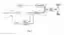
FIG. 1 is a structural block diagram of an existing hybrid powered vehicle system;
FIG. 2 is a control flowchart for a battery being charged according to an embodiment of the invention;
FIG. 3 is a control flowchart for a battery being discharged according to an embodiment of the invention;
FIG. 4 is a schematic structural diagram of a device for protective limiting of charging and discharging current of a battery in a hybrid powered vehicle according to an embodiment of the invention;
FIG. 5 is a schematic structural diagram of a second processing unit in the device illustrated in FIG. 4;
FIG. 6 is another schematic structural diagram of the second processing unit in the device illustrated in FIG. 4; and
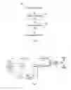
FIG. 7 is a schematic structural diagram of a hybrid powered vehicle system according to an embodiment of the invention.
DETAILED DESCRIPTION OF THE INVENTION
With reference to FIG. 1 illustrating a structural block diagram of an existing hybrid powered vehicle system, a Battery Management System (BMS) feeds back battery related parameters to a Hybrid Control Unit (HCU), the HCU sends a torque request to an Engine Management System (EMS) and a Motor Control Unit (MCU) upon reception of a power request, and output torques of a motor and of an engine are superposed to provide a torque required for the vehicle, which is transmitted to a power transmission system and finally wheels to drive the vehicle to run. The magnitude of the torque request sent from the HCU to the MCU determines the magnitude of charging and discharging current of a high voltage battery. The invention is intended to limit the torque request for the purpose of protective limiting of charging and discharging current of battery.
The technical solutions in the embodiments of the invention will be clearly and fully described below with reference to the drawings in the embodiments of the invention to enable those skilled in the art to clearly understand the technical solutions of the invention, and evidently the embodiments to be described are merely a part but not all of the embodiments of the invention. All the other embodiments derived by those ordinarily skilled in the art from the embodiments here without any inventive effort shall come into the protection of scope of the invention.
The HCU determines from voltage and current signals of the high voltage battery whether the battery is in a charging or discharging state, that is, the battery is in a discharging state in the case of positive current or in a charging state in the case of negative current.
1. When the battery is in a charging state, the HCU multiplies an actually measured voltage value of the battery by a charging current limit value of the battery to derive a charging limit power P1;
When the actual current value is below an initial control value of charging current (which is experimentally determined from a feature of the battery), an output limit power Plimit—1 is P1, a limit torque value is calculated from the output limit power and an angular velocity of the motor and the limit torque value is compared with the requested torque received by the Hybrid Control Unit, and the smaller one of them is a torque request value to be finally sent from the Hybrid Control Unit to the MCU.
When the actual current value is above the initial control value of charging current, PI adjusting is performed with Ierror=Ibattery−Icharge—limit to derive a torque deviation value PPI—1, where Ibattery is the actually measured current value of the battery, and Icharge—limit is the charging current limit value of the battery.
A resultant output limit power is derived from PPI—1 and P1, i.e., Plimit—1=P1+PPI—1, a limit torque value is calculated from the output limit power Plimit—1 and an angular velocity of the motor and the limit torque value is compared with the requested torque received by the Hybrid Control Unit, and the smaller one of them is a torque request value to be finally sent from the Hybrid Control Unit to the Motor Control Unit MCU.
2. When the battery is in a discharging state, the HCU multiplies an actually measured voltage value of the battery by a discharging current limit value of the battery to derive a discharging limit power P2;
When the actual current value is below an initial control value of discharging current (which is experimentally determined from a feature of the battery), a output limit power Plimit—2 is P2, a limit torque value is calculated from the output limit power and an angular velocity of the motor and the limit torque value is compared with the requested torque received by the Hybrid Control Unit, and the smaller one of them is a torque request value to be finally sent from the Hybrid Control Unit to the MCU.
When the actual current value is above the initial control value of discharging current, PI adjusting is performed with Ierror=Ibattery−Idischarge—limit to derive a torque deviation value PPI—2, where Ibattery is the actually measured current value of the battery, and Idischarge—limit is the discharging current limit value of the battery.
A resultant output limit power is derived from PPI—2 and P2, i.e., Plimit—2=P2+PPI—2, a limit torque value is calculated from the output limit power Plimit—2 and an angular velocity of the motor and the limit torque value is compared with the requested torque received by the Hybrid Control Unit, and the smaller one of them is a torque request value to be finally sent from the Hybrid Control Unit to the Motor Control Unit.
Generally, a specific process of the method for protective limiting of charging and discharging current of a battery in a hybrid powered vehicle according to an embodiment of the invention is as follows: it is determined whether the battery is in a charging or discharging state; and if it is in a charging state, then a flow corresponding to a charging state proceeds, or if it is in a discharging state, a flow corresponding to a discharging state proceeds.
Where the control flow corresponding to a charging state as illustrated in FIG. 2 includes the following steps:
Step S21. An actually measured voltage value of the battery is multiplied by a charging current limit value of the battery to derive a charging limit power P1.
Step S22. It is determined whether the actual current value is below an initial control value of charging current, and if so, the flow goes to the step S23; otherwise, the flow goes to the step S24.
Step S23. An output limit power Plimit—1 is P1, a limit torque value is calculated from the output limit power and an angular velocity of a motor, and the flow goes to the step S27.
Step S24. PI adjusting is performed with Ierror=Ibattery−Icharge—limit to derive a torque deviation value PPI—1, where Ibattery is the actually measured current value of the battery, and Icharge—limit is the charging current limit value of the battery, and the flow goes to the step S25.
Step S25-step S26. A resultant output limit power is derived from PPI—1 and P1, i.e., Plimit—1=P1+PPI—1, a limit torque value is calculated from the output limit power Plimit—1 and an angular velocity of the motor, and the flow goes to the step S27.
Step S27. The limit torque value is compared with a requested torque received by a Hybrid Control Unit, and the smaller one of them is taken as a torque request value to be sent from the Hybrid Control Unit.
Where the control flow corresponding to a discharging state as illustrated in FIG. 3 includes the following steps:
Step S31. An actually measured voltage value of the battery is multiplied by a discharging current limit value of the battery to derive a discharging limit power P2.
Step S32. It is determined whether the actual current value is below an initial control value of discharging current, and if so, the flow goes to the step S33; otherwise, the flow goes to the step S34.
Step S33. A output limit power Plimit—2 is P2, a limit torque value is calculated from the output limit power and an angular velocity of a motor, and the flow goes to the step S37.
Step S34. PI adjusting is performed with Ierror=Ibattery−Idischarge—limit to derive a torque deviation value PPI—2, where Ibattery is the actually measured current value of the battery, and Idischarge—limit is the discharging current limit value of the battery, and the flow goes to the step S35.
Step S35-step S36. A resultant output limit power is derived from PPI—2 and P2, i.e., Plimit—2=P2+PPI—2, a limit torque value is calculated from the output limit power Plimit—2 and an angular velocity of the motor, and the flow goes to the step S37.
Step S37. The limit torque value is compared with a requested torque received by a Hybrid Control Unit, and the smaller one of them is taken as a torque request value to be sent from the Hybrid Control Unit.
As can be seen, in the embodiment of the invention, charging and discharging current can be monitored in real time, and an output torque of the motor is controlled according to variation of current to thereby limit current of the battery within a range for normal operation and achieve a better effect of protective limiting of charging and discharging current of the battery.
An embodiment of the invention further provides a device for implementing the foregoing method as structured in FIG. 4, which includes a first processing unit 41, a second processing unit 42, a third processing unit 43 and a fourth processing unit 44.
Where:
The first processing unit 41 is adapted to receive a power request and to determine an initial torque value in response to the power request.
The second processing unit 42 is adapted to determine a charging or discharging state of the battery and to calculate a charging or discharging limit power value of the battery from BMS feedback values, where, the BMS feedback values include present maximum charging current, maximum discharging current, maximum voltage, minimum voltage, actual current value and actual voltage value of the battery.
The third processing unit 43 is adapted to calculate a limit torque value from the limit power value and an angular velocity of a motor.
The fourth processing unit 44 is adapted to compare the initial torque value and the limit torque value and to select the smaller one of them as a torque request value to be finally output.
Where the second processing unit 42 can include a first processing sub-unit and a second processing sub-unit: where the first processing sub-unit is adapted to calculate a charging limit power value of the battery when the battery is in a charging state: an actually measured voltage value of the battery is multiplied by a charging current limit value of the battery to derive a charging limit power P1; and the second processing sub-unit is adapted to calculate a discharging limit power value of the battery when the battery is in a discharging state: an actually measured voltage value of the battery is multiplied by a discharging current limit value of the battery to derive a discharging limit power P2.
FIG. 5 illustrates a structural form of the third processing unit 43 including:
A first comparison unit 51 adapted to compare the actual current value and an initial control value of charging current;
A first calculation unit 52 adapted to take a output limit power Plimit—1 as P1 and calculate a limit torque value from the output limit power and an angular velocity of the motor when the actual current value is below the initial control value of charging current.
Moreover, the first calculation unit 52 can further be adapted to perform PI adjusting with Ierror=Ibattery−Icharge—limit to derive a torque deviation value PPI—1 when the actual current value is above the initial control value of charging current, where Ibattery is the actually measured current value of the battery, and Icharge—limit is the charging current limit value of the battery, to derive a resultant output limit power Plimit—1=P1+PPI—1 from PPI—1 and P1, and to calculate a limit torque value from the output limit power Plimit—1 and an angular velocity of the motor.
FIG. 6 illustrates another possible structural form of the third processing unit 43 including a second comparison unit 61 and a second calculation unit 62.
The second comparison unit 61 is adapted to compare the actual current value and an initial control value of discharging current;
The second calculation unit 62 is adapted to take a output limit power Plimit—2 as P2 and calculate a limit torque value from the output limit power and an angular velocity of the motor when the actual current value is below the initial control value of discharging current.
Moreover, the second calculation unit 62 can further be adapted to perform PI adjusting with Ierror=Ibattery−Idischarge—limit to derive a torque deviation value PPI—2 when the actual current value is above the initial control value of discharging current, where Ibattery is the actually measured current value of the battery, and Idischarge—limit is the discharging current limit value of the battery, to derive a resultant output limit power Plimit—2=P2+PPI—2 from PPI—2 and P2, and to calculate a limit torque value from the output limit power Plimit—2 and an angular velocity of the motor.
Moreover, an embodiment of the invention further provides a hybrid powered vehicle system as illustrated in FIG. 7, which includes a BMS 71, an HCU 72, an EMS 73, an MCU 74, a motor 75, an engine 76, a synthesizer 77 and a power transmission system. The HCU 72 includes a device for protective limiting of charging and discharging current of a battery (simply referred to as protection device) 721.
The protection device 721 is adapted to receive a power request and determine an initial torque value in response to the power request; to determine a charging or discharging state of the battery and calculate a limit torque value from an actual current value and a predetermined limit value; and to compare the initial torque value and the limit torque value and select the smaller one of them as a torque request value to be finally output.
The protection device 721 determines a charging or discharging state of the battery according to battery related parameters (voltage and current signals of the battery) fed back from the BMS 71. The protection device 721 transmits the torque request value to the EMS 73 and the MCU 74, both the motor 75 and the engine 76 output a torque under the control of the EMS 73 and the MCU 74, and the synthesizer 77 superposes the output torque of the motor 75 and the output torque of the engine 76 and transmits a resultant torque to the power transmission system 78 and finally wheels to drive a vehicle to run.
For details of the specific components and structure of the protection device 721, reference can be made to the foregoing descriptions of the device as well as FIG. 4, FIG. 5 and FIG. 6.
Those skilled in the art can appreciate that information, a message and a signal can be represented with any one of various processes and techniques. For example, the message and information mentioned in the foregoing descriptions can be represented as a voltage, current, electromagnetic wave, magnetic field, magnetic particle or any combination thereof.
Those skilled in the art can further appreciate that the respective illustrative units and algorithm steps described in connection with the embodiments disclosed in the specification can be implemented with electric hardware, computer software or a combination of both, and the respective illustrative components and steps have been functionally described in general as above in order to clearly describe interchangeability of hardware and software. Whether these functions are implemented in hardware or software depends upon specific applications and design constraining conditions of technical solutions. Those skilled in the art can implement the described functions using different methods for each specific application without departing from the scope of the invention.
The steps of the method or algorithm described in connection with the embodiments disclosed in the specification can be implemented directly in hardware, a software module executed by a processor or a combination of both. The software module can be built in a Random Access Memory (RAM), a memory, a Read Only Memory (ROM), an electrically programmable ROM, an electrically erasable programmable ROM, a register, a hard disk, a removable disk, a CD-ROM or a storage medium in any other form well known in the art.
The foregoing descriptions of the disclosed embodiments enable those skilled in the art to implement or use the invention. Various modifications of these embodiments are apparent to those skilled in the art, and the general principal defined in the specification can be put into practice in other embodiments without departing from the spirit or scope of the invention. Therefore, the invention will not be limited to these embodiments illustrated here but will be accorded with the broadest scope in agreement with the principal and novel features disclosed here.
Claims
What is claimed is:1. A method for protective limiting of charging and discharging current of a battery in a hybrid powered vehicle, comprising:
receiving a power request and determining an initial torque value in response to the power request;
determining a charging or discharging state of the battery and calculating a limit torque value from an actual current value and a predetermined limit value; and
comparing the initial torque value and the limit torque value and selecting the smaller one of them as a torque request value to be finally output.
2. The method according to claim 1, wherein when the battery is in a charging state, calculating the limit torque value comprises:
when the battery is in a charging state, multiplying by a Hybrid Control Unit an actually measured voltage value of the battery by a charging current limit value of the battery to derive a charging limit power P1; and
when the actual current value is below an initial control value of charging current, taking a output limit power Plimit—1 as P1, and calculating a limit torque value from the output limit power and an angular velocity of the motor.
3. The method according to claim 2, wherein calculating the limit torque value further comprises:
when the actual current value is above the initial control value of charging current, performing PI adjusting with Ierror=Ibattery−Icharge—limit to derive a torque deviation value PPI—1, wherein Ibattery is the actually measured current value of the battery, and Icharge—limit is the charging current limit value of the battery; deriving a resultant output limit power Plimit—1=P1+PPI—1 from PPI—1 and P1; and calculating a limit torque value from the output limit power Plimit—1 and an angular velocity of the motor.
4. The method according to claim 1, wherein calculating the limit torque value comprises:
when the battery is in a discharging state, multiplying by a Hybrid Control Unit an actually measured voltage value of the battery by a discharging current limit value of the battery to derive a discharging limit power P2; and
when the actual current value is below an initial control value of discharging current, taking a output limit power Plimit—2 as P2, and calculating a limit torque value from the output limit power and an angular velocity of the motor.
5. The method according to claim 4, wherein calculating the limit torque value further comprises:
when the actual current value is above the initial control value of discharging current, performing PI adjusting with Ierror=Ibattery−Idischarge—limit to derive a torque deviation value PPI—2, wherein Ibattery is the actually measured current value of the battery, and Idischarge—limit is the discharging current limit value of the battery; deriving a resultant output limit power Plimit—2=P2+PPI—2 from PPI—2 and P2; and calculating a limit torque value from the output limit power Plimit—2 and an angular velocity of the motor.
6. The method according to claim 1, wherein determining a charging or discharging state of the battery comprises: determining a charging or discharging state of the battery from voltage and current signals of the high voltage battery.
7. A device for protective limiting of charging and discharging current of a battery in a hybrid powered vehicle, comprising:
a first processing unit adapted to receive a power request and to determine an initial torque value in response to the power request;
a second processing unit adapted to determine a charging or discharging state of the battery and to calculate a limit power value of charging or discharging the battery from BMS feedback values;
a third processing unit adapted to calculate a limit torque value from the limit power value and an angular velocity of a motor; and
a fourth processing unit adapted to compare the initial torque value and the limit torque value and to select the smaller one of them as a torque request value to be finally output.
8. The device according to claim 7, wherein the third processing unit comprises:
a first comparison unit 51 adapted to compare an actual current value and an initial control value of charging current; and
a first calculation unit 52 adapted to calculate a limit torque value from the output limit power P1 and an angular velocity of the motor when the actual current value is below the initial control value of charging current, and to perform PI adjusting with Ierror=Ibattery−Icharge—limit to derive a torque deviation value PPI—1, where Ibattery is the actually measured current value, and Icharge—limit is the charging current limit value of the battery, to derive a resultant output limit power Plimit—1=P1+PPI—1 from PPI—1 and P1, and to calculate a limit torque value from the output limit power Plimit—1 and an angular velocity of the motor when the actual current value is above the initial control value of charging current.
9. The device according to claim 7, wherein the third processing unit comprises:
a second comparison unit adapted to compare an actual current value and an initial control value of discharging current; and
a second calculation unit adapted to calculate a limit torque value from the output limit power P2 and an angular velocity of the motor when the actual current value is below the initial control value of discharging current; and to perform PI adjusting with Ierror=Ibattery−Idischarge—limit to derive a torque deviation value PPI—2, wherein Ibattery is the actually measured current value of the battery, and Idischarge—limit is the discharging current limit value of the battery, to derive a resultant output limit power Plimit—2=P2+PPI—2 from PPI—2 and P2, and to calculate a limit torque value from the output limit power Plimit—2 and an angular velocity of the motor when the actual current value is above the initial control value of discharging current.
10. A hybrid powered vehicle system, comprising a Battery Management System BMS, a Hybrid Control Unit HCU, an Engine Management System EMS, a Motor Control Unit MCU, a motor, an engine, a synthesizer and a power transmission system, wherein the HCU comprises a device for protective limiting of charging and discharging current of a battery and the device comprises:
a first processing unit adapted to receive a power request and to determine an initial torque value in response to the power request;
a second processing unit adapted to determine a charging or discharging state of the battery and to calculate a limit power value of charging or discharging the battery from BMS feedback values;
a third processing unit adapted to calculate a limit torque value from the limit power value and an angular velocity of a motor; and
a fourth processing unit adapted to compare the initial torque value and the limit torque value and to select the smaller one of them as a torque request value to be finally output.
Images & Drawings included:


Sources:
- United States Patent and Trademark Office - verify current appl. status at the USPTO↗
Recent applications in this class:
- » 20250187426 2025-06-12
SYSTEM AND METHOD OF A MOBILE ELECTRICAL SYSTEM - » 20250187425 2025-06-12
SYSTEM AND METHOD OF A MOBILE ELECTRICAL SYSTEM - » 20250187424 2025-06-12
PARALLEL HYBRID SYSTEM WITH ELECTRIC MOTOR FOR VEHICLE - » 20240399847 2024-12-05
SADDLE-RIDE MOTORCYCLE OF SCOOTER TYPE WITH HYBRID PROPULSION - » 20240239179 2024-07-18
Pump assembly in a transmission and pump assembly operating method - » 20240227535 2024-07-11
System and method of a mobile electrical system - » 20230415562 2023-12-28
HYBRID DRIVE UNIT - » 20230398853 2023-12-14
TRANSMISSION UNIT AND POWER SYSTEM - » 20230391180 2023-12-07
Drive system of hybrid utility vehicle - » 20230356583 2023-11-09
Hybrid drive assembly for a motor vehicle
Recent applications for this Assignee:
- » 20170298855 2017-10-19
Method and apparatus for acquiring altitude correction coefficient - » 20170250836 2017-08-31
Method and apparatus for message transmission - » 20110218748 2011-09-08
Apparatus for monitoring battery voltage and temperature - » 20110101713 2011-05-05
Lock device for sliding door - » 20110100311 2011-05-05
Variable valve lift system for an internal combustion engine - » 20110094286 2011-04-28
Press mold - » 20100305797 2010-12-02
Motor torque smoothing treatment method for hybrid power and a hybrid power system - » 20100294596 2010-11-25
Lubricant grease charging-up device for automobile brake hub bearing - » 20100286855 2010-11-11
Torque management method for hybrid electric motor