Internal combustion engine that can be operated with different types of liquid fuel
US20100252004A1
2010-10-07
12/742,536
2008-10-10
✅ Patent granted
US 8,443,783 B2
2013-05-21
WO; PCT/EP2008/063603; 20081010
WO; WO2009/062795; 20090522
Hai Huynh
Maginot, Moore & Beck
2029-11-04
Abstract:
The invention relates to an internal combustion engine that can be operated with different types of liquid fuel, which includes a device that can determine the current type of liquid fuel used. The invention further relates to a method for operating such an internal combustion engine. According to the invention, at least two different paths are provided, by which the liquid fuel can reach the combustion chamber of the internal combustion engine. The internal combustion engine comprises a control and regulation device, controlling or regulating the use of the different paths as a function of the type of the liquid fuel that was determined.
Assignee:
- Robert Bosch GMBH 19,123 🇩🇪 Stuttgart, Germany
Applicant:
Interested in similar patents?
Get notified when new applications in this technology area are published.
Classification:
F02D41/0025 » CPC main
Electrical control of supply of combustible mixture or its constituents Controlling engines characterised by use of non-liquid fuels, pluralities of fuels, or non-fuel substances added to the combustible mixtures
F02D19/0628 » CPC further
Controlling engines characterised by their use of non-liquid fuels, pluralities of fuels, or non-fuel substances added to the combustible mixtures peculiar to engines working with pluralities of fuels, e.g. alternatively with light and heavy fuel oil, other than engines indifferent to the fuel consumed; Measuring or estimating parameters related to the fuel supply system Determining the fuel pressure, temperature or flow, the fuel tank fill level or a valve position
F02D19/0689 » CPC further
Controlling engines characterised by their use of non-liquid fuels, pluralities of fuels, or non-fuel substances added to the combustible mixtures peculiar to engines working with pluralities of fuels, e.g. alternatively with light and heavy fuel oil, other than engines indifferent to the fuel consumed; Details on the fuel supply system, e.g. tanks, valves, pipes, pumps, rails, injectors or mixers; Injectors for in-cylinder direct injection
F02D19/0692 » CPC further
Controlling engines characterised by their use of non-liquid fuels, pluralities of fuels, or non-fuel substances added to the combustible mixtures peculiar to engines working with pluralities of fuels, e.g. alternatively with light and heavy fuel oil, other than engines indifferent to the fuel consumed; Details on the fuel supply system, e.g. tanks, valves, pipes, pumps, rails, injectors or mixers; Injectors Arrangement of multiple injectors per combustion chamber
F02D19/084 » CPC further
Controlling engines characterised by their use of non-liquid fuels, pluralities of fuels, or non-fuel substances added to the combustible mixtures peculiar to engines working with pluralities of fuels, e.g. alternatively with light and heavy fuel oil, other than engines indifferent to the fuel consumed simultaneously using pluralities of fuels; Premixed fuels, i.e. emulsions or blends Blends of gasoline and alcohols, e.g. E85
F02D19/087 » CPC further
Controlling engines characterised by their use of non-liquid fuels, pluralities of fuels, or non-fuel substances added to the combustible mixtures peculiar to engines working with pluralities of fuels, e.g. alternatively with light and heavy fuel oil, other than engines indifferent to the fuel consumed simultaneously using pluralities of fuels; Premixed fuels, i.e. emulsions or blends; Control based on the fuel type or composition with determination of densities, viscosities, composition, concentration or mixture ratios of fuels
F02D41/3094 » CPC further
Electrical control of supply of combustible mixture or its constituents; Controlling fuel injection the fuel injection being effected by at least two different injectors, e.g. one in the intake manifold and one in the cylinder
F02M43/00 » CPC further
Fuel-injection apparatus operating simultaneously on two or more fuels, or on a liquid fuel and another liquid, e.g. the other liquid being an anti-knock additive
F02M69/046 » CPC further
Low-pressure fuel-injection apparatus ; Apparatus with both continuous and intermittent injection; Apparatus injecting different types of fuel; Injectors peculiar thereto; Positioning of injectors with respect to engine, e.g. in the air intake conduit for injecting into both the combustion chamber and the intake conduit
F02D41/062 » CPC further
Electrical control of supply of combustible mixture or its constituents; Circuit arrangements for generating control signals; Introducing corrections for particular operating conditions for engine starting or warming up for starting
F02D2200/0611 » CPC further
Input parameters for engine control the parameters being related to the engine; Fuel or fuel supply system parameters Fuel type, fuel composition or fuel quality
F02M37/0064 » CPC further
Apparatus or systems for feeding liquid fuel from storage containers to carburettors or fuel-injection apparatus; Arrangements for purifying liquid fuel specially adapted for, or arranged on, internal-combustion engines; Layout or arrangement of systems for feeding fuel for engines being fed with multiple fuels or fuels having special properties, e.g. bio-fuels; varying the fuel composition
Y02T10/30 » CPC further
Road transport of goods or passengers; Internal combustion engine [ICE] based vehicles Use of alternative fuels, e.g. biofuels
Y02T10/30 » CPC further
Road transport of goods or passengers; Internal combustion engine [ICE] based vehicles Use of alternative fuels, e.g. biofuels
Y10T137/877 » CPC further
Fluid handling; Systems With flow control means for branched passages
F02M37/04 IPC
Apparatus or systems for feeding liquid fuel from storage containers to carburettors or fuel-injection apparatus; Arrangements for purifying liquid fuel specially adapted for, or arranged on, internal-combustion engines Feeding by means of driven pumps
F02B13/00 IPC
Engines characterised by the method of introducing liquid fuel into cylinders
F02B13/00 IPC
Engines characterised by the introduction of liquid fuel into cylinders by use of auxiliary fluid
F16K7/00 IPC
Diaphragm cut-off apparatus, e.g. with a member deformed, but not moved bodily, to close the passage
F02B7/02 IPC
Engines characterised by the fuel-air charge being ignited by compression ignition of an additional fuel the fuel in the charge being liquid
Description
PRIOR ART
The invention relates to an internal combustion engine that can be operated with different of liquid fuels, including in particular ethanol, methanol and gasoline, as generically defined by the preamble to claim 1, and to a method for operating such an engine as generically defined by the preamble to the coordinate claim.
So-called “flex-fuel injection systems” are known on the market. Such injection systems make it possible for vehicles to put ethanol, methanol, as well as gasoline in their tanks. With the aid of sensors or models, the particular fuel composition in the tank is detected. In accordance with this, engine operation is adapted by a control and regulating device, for instance by means of a specific adjustment of the instant of ignition, the instant of injection, and the injection quantity. In flex-fuel injection systems, accordingly, only a single tank is employed, in which the various fuel types ethanol, methanol and gasoline are stored either alone or in arbitrary mixture ratios. Thus when here and below different types of liquid fuels are mentioned, this includes both different fuels and different fuel mixtures.
DISCLOSURE OF THE INVENTION
It is the object of the present invention to furnish an internal combustion engine of the type defined at the outset, and a method for its operation, so that compared to previous internal combustion engines, improved emission performance as well as fuel consumption are attained.
This object is attained by an internal combustion engine having the characteristics of claim 1 and by a method having the characteristics of the coordinate claim. Advantageous refinements are moreover recited in dependent claims. Characteristics important to the invention are also found in the ensuing description and the drawings; these characteristics may be essential to the invention both alone and in combination, without explicit reference thereto.
Different types of liquid fuels differ, among other ways, in their energy content. So that the engine can produce a defined torque, a greater quantity of one type of a liquid fuel must reach the combustion chamber per work cycle than is the case in a different type of liquid fuel. In the engine according to the invention, the requisite fuel quantity is split between the two different paths, over which the liquid fuel can reach the combustion chamber of the engine, in such a way that all in all the total demand of the engine to enable it to generate a desired torque is optimally covered. Splitting between the two paths is preferably done such that the emissions and fuel consumption are optimal.
Because two different paths are available, the additionally required fuel, for instance in operation with methanol or ethanol, which have a comparatively low energy content, can be made available without problems. Therefore neither of the two paths has to be designed for an especially high maximum quantity that in turn could adversely affect the accuracy of metering small quantities. The same is true for the delivery rate of a corresponding fuel pump. The pump can be designed for the particularly critical case of cold starting, so that the starting behavior of the engine is improved as well.
In a first refinement of the internal combustion engine according to the invention, it is proposed that a first path, over which the liquid fuel can reach the combustion chamber, includes at least a first injector, which injects the liquid fuel directly into the combustion chamber; and that a second path, over which the liquid fuel can reach the combustion chamber, includes at least one second injector, which injects the liquid fuel into an intake tube. In this refinement, direct injection is accordingly combined with an intake tube injection. Thus the provisions for optimizing emissions that are known from direct injection can be employed, such as the possibility of splitting the injection into various partial injections (preinjection, main injection, and postinjection), the adjustment of the timing of the onset of injection, and/or varying the injection pressure. An intake tube injection, conversely, offers advantages of partial load and high load at low engine rpm and expands the possibilities for heating a catalytic converter. Moreover, an additional intake tube injection can also be added to existing concepts of internal combustion engines without necessitating complex, expensive modifications of the engine. It is even conceivable to retrofit already existing engines with such additional intake tube injection and thus make them usable for flex-fuel.
Accordingly, thanks to the invention, it is necessary neither to enlarge the high-pressure pump of the direct injection system nor to design the injectors, which inject the fuel directly into the combustion chamber, for an increased flow rate (which could have adverse effects on small-quantity metering and would necessitate an increased end-stage power for triggering the injector), nor is an enlarged high-pressure fuel reservoir (“rail”), which could lead to problems with pressure buildup, especially in a high-pressure start, necessary. The additional intake tube injection can be achieved by installing merely a second low-pressure injector and a corresponding fuel allocator. All other components necessary for the intake tube injection are already present in an internal combustion engine that has direct injection.
At least one second injector can be associated with each intake tube leading to a combustion chamber. This would be equivalent to individual-cylinder injection, as is usual in intake tube injection systems (“ITI”) that are conventional today. This makes especially quiet, low-emission operation of the engine possible. However, at least one second injector can be associated with an intake tube manifold that is associated with a plurality of combustion chambers, and this can be achieved economically.
Preferably, the first path (direct injection into a combustion chamber) is designed predominantly for injecting at least essentially pure gasoline. In practice; that should be the fuel predominantly used even in flex-fuel systems, which in most operating situations of the engine contributes to optimal engine operation. Then, each system by way of which the liquid fuel is injected into an intake tube is consistently directed above all to the additional demand for fuel in the form of ethanol and methanol and mixtures of gasoline, ethanol and methanol.
It is also advantageous if the control and regulating device additionally controls or regulates the use of the different paths as a function of at least one further operating parameter of the engine. Thus the advantages of the presence of two different paths is made usable, for instance for different engine operating situations, such as the improved mixture preparation, already mentioned above, in partial- and high-load operation at low engine rpm, as well as expanded catalytic converter heating provisions.
BRIEF DESCRIPTION OF THE DRAWINGS
Embodiments of the invention will be explained in further detail below in conjunction with the accompanying drawings. In the drawings:
FIG. 1 is a schematic illustration of a first embodiment of an internal combustion engine;
FIG. 2 is a flow chart of a method for operating the engine of FIG. 1;
FIG. 3 is a simplified schematic illustration of a second embodiment of an internal combustion engine.
EMBODIMENTS OF THE INVENTION
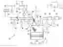
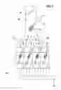
In FIG. 1, an internal combustion engine is identified overall by reference numeral 10. It includes a plurality of cylinders that are essentially constructed identically, but of which in FIG. 1 only one is shown as an example, identified by reference numeral 12. The cylinder 12 has a combustion chamber 14, which is defined by a piston 16. This piston is connected to a crankshaft 18 that is shown only schematically.
Fresh air is delivered to the combustion chamber 14 via an inlet valve 20 and an intake tube 22, while conversely combustion exhaust gases are carried away via an outlet valve 24 and an exhaust tube 26. A throttle valve 28 is disposed in the intake tube, and a precatalytic converter 30 and a main catalytic converter 32 are disposed in the exhaust tube 26.
The engine 10 is operated with different types of liquid fuels, such as ethanol, methanol, gasoline, and arbitrary mixtures of those components. The liquid fuel 33 is stored in a tank 34, from which it is delivered by a low-pressure pump 36 to a low-pressure line 38. The current type of liquid fuel 33 is detected by a sensor 40. In an embodiment not shown, the current type is ascertained from the behavior of the engine with reference to a model. A high-pressure pump 42, among other things, is connected to the low-pressure line 38 and delivers the fuel 33 to a pressure reservoir 44 (“rail”). A first injector 46 is connected to this rail and can inject the fuel 33 directly into the combustion chamber 14.
Also connected directly to the low-pressure line 38 is a second injector 48, which can inject the fuel, directly upstream of the inlet valve 20, into the intake tube 22 associated with the combustion chamber 14. Thus the first injector 46 belongs to a first path over which the liquid fuel 33 can reach the combustion chamber 14, and the second injector 48 belongs to a second path over which the fuel can reach the combustion chamber 14. The first path corresponds to a principle that is also known as “gasoline direct injection”, while the second path corresponds to the principle that is also known as “intake manifold injection”. The fuel 33 injected into the combustion chamber 14 is ignited by a spark plug 50 that is connected to an ignition system 52.
The operation of the internal combustion engine 10 is controlled and regulated by a control and regulating device 54. This device receives signals from various sensors, thus including the sensor 40 that detects or ascertains the type of liquid fuel 33. It also receives signals from an HFM sensor, which detects the flow rate of air flowing in the intake tube 22, and from a pressure sensor 58, which detects the pressure prevailing in the intake tube 22 downstream of the throttle valve 28. An rpm sensor 60 forwards a signal corresponding to the rpm of the crankshaft 18 to the control and regulating device 54, and two lambda sensors 62 and 64, disposed upstream of the respective catalytic converters 30 and 32, likewise forward corresponding signals. A temperature sensor and a knocking sensor on the cylinder 12 and a pressure sensor on the rail 44 are not shown for the sake of simplicity in the drawing.
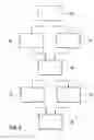
The engine 10 is operated as follows (see FIG. 2): After a start at 66, the type of liquid fuel 33 currently being used is ascertained by the control and regulating device 54 at 68 on the basis of the signal of the sensor 40. This fuel may be gasoline, ethanol, methanol, or arbitrary mixtures of these substances. Simultaneously, at 70, the current operating system of the engine 10 is ascertained or detected. Such an operating situation may for instance be starting of the engine 10, or it may be defined simply by the desired load or the desired torque and the current rpm. At 72, the control and regulating device 54 ascertains how the fuel quantity required for the current operating situation is to be split to the two injectors 46 and 48. This splitting, that is, the use of the two injectors 46 and 48, is accordingly done as a function on the one hand of the ascertained type of liquid fuel 33 and on the other of the current operating situation, which is defined by various current and desired operating parameters of the engine 10. In accordance with the splitting defined at 72, the injectors 46 and 48 are triggered at 74 and 76. The method ends at 80.
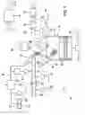
In FIG. 3, a region is shown of an alternative embodiment of an internal combustion engine 10. Those elements and regions that have equivalent functions to elements and regions of the internal combustion engine 10 shown in FIG. 1 are identified by the same reference numerals and will not be described again in detail.
The engine 10 shown in FIG. 3 differs from that in FIG. 1 in that not every intake tube 22 that is associated with a combustion chamber 14 has a respective second injector; instead, there is a single second injector disposed in an intake tube manifold 80 that is present upstream of the intake tubes 22.
Claims
1-9. (canceled)
10. An internal combustion engine, which can be operated with different types of liquid fuels, including in particular ethanol, methanol and gasoline, and which has a device that can ascertain a current type of liquid fuel, the engine having at least two different paths provided along which the liquid fuel can reach a combustion chamber of the engine, and having a control and regulating device, which controls or regulates the use of the different paths as a function of the type of liquid fuel ascertained.
11. The internal combustion engine as defined by claim 10, wherein a first path of the at least two different paths, over which the liquid fuel can reach the combustion chamber, includes at least a first injector, which injects the liquid fuel directly into the combustion chamber; and that a second path of the at least two different paths, over which the liquid fuel can reach the combustion chamber, includes at least one second injector, which injects the liquid fuel into an intake tube.
12. The internal combustion engine as defined by claim 11, wherein at least one second injector is associated with each intake tube leading to a combustion chamber.
13. The internal combustion engine as defined by claim 11, wherein at least one second injector is associated with an intake tube manifold, which is associated with a plurality of combustion chambers.
14. The internal combustion engine as defined by claim 12, wherein at least one second injector is associated with an intake tube manifold, which is associated with a plurality of combustion chambers.
15. The internal combustion engine as defined by claim 11, wherein the first path is designed predominantly for injecting at least essentially pure gasoline.
16. The internal combustion engine as defined by claim 12, wherein the first path is designed predominantly for injecting at least essentially pure gasoline.
17. The internal combustion engine as defined by claim 13, wherein the first path is designed predominantly for injecting at least essentially pure gasoline.
18. The internal combustion engine as defined by claim 14, wherein the first path is designed predominantly for injecting at least essentially pure gasoline.
19. The internal combustion engine as defined by claim 10, wherein the control and regulating device additionally controls or regulates the use of the different paths as a function of at least one further operating parameter of the engine.
20. The internal combustion engine as defined by claim 11, wherein the control and regulating device additionally controls or regulates the use of the different paths as a function of at least one further operating parameter of the engine.
21. The internal combustion engine as defined by claim 12, wherein the control and regulating device additionally controls or regulates the use of the different paths as a function of at least one further operating parameter of the engine.
22. The internal combustion engine as defined by claim 13, wherein the control and regulating device additionally controls or regulates the use of the different paths as a function of at least one further operating parameter of the engine.
23. The internal combustion engine as defined by claim 15, wherein the control and regulating device additionally controls or regulates the use of the different paths as a function of at least one further operating parameter of the engine.
24. The internal combustion engine as defined by claim 11, wherein the second injector is connected to a region of a fuel line that is located upstream of a high-pressure pump, and the first injector is connected to a region of the fuel line that is located downstream of the high-pressure pump.
25. The internal combustion engine as defined by claim 12, wherein the second injector is connected to a region of a fuel line that is located upstream of a high-pressure pump, and the first injector is connected to a region of the fuel line that is located downstream of the high-pressure pump.
26. The internal combustion engine as defined by claim 13, wherein the second injector is connected to a region of a fuel line that is located upstream of a high-pressure pump, and the first injector is connected to a region of the fuel line that is located downstream of the high-pressure pump.
27. The internal combustion engine as defined by claim 15, wherein the second injector is connected to a region of a fuel line that is located upstream of a high-pressure pump, and the first injector is connected to a region of the fuel line that is located downstream of the high-pressure pump.
28. A method for operating an internal combustion engine with different types of liquid fuels, in particular including ethanol, methanol and gasoline, comprising the steps of:
ascertaining a current type of liquid fuel;
providing different paths for the liquid fuel to reach a combustion chamber of the engine; and
using the different paths depending on the type of liquid fuel ascertained.
29. The method as defined by claim 28, wherein the fuel can be injected both directly into the combustion chamber and into an intake tube.
Images & Drawings included:
Sources:
- United States Patent and Trademark Office - verify current appl. status at the USPTO↗
Recent applications in this class:
- » 20250059907 2025-02-20
METHOD OF OPERATING A WATER INJECTION SYSTEM - » 20240271580 2024-08-15
Compression-ignition engine operating strategy using early pilot shots of methanol fuel - » 20230323827 2023-10-12
Controller and control method for internal combustion engine - » 20230304452 2023-09-28
Controller and control method for engine - » 20230101071 2023-03-30
Combustion control for ammonia fueled engine - » 20220389879 2022-12-08
Optimized fuel management system for direct injection ethanol enhancement of gasoline engines - » 20220195952 2022-06-23
Method to control the combustion of an internal combustion engine - » 20220186674 2022-06-16
System, apparatus, and method for controlling an engine system to account for varying fuel quality - » 20220120227 2022-04-21
Fuel quality indicator - » 20220034272 2022-02-03
Optimized fuel management system for direct injection ethanol enhancement of gasoline engines
Recent applications for this Assignee:
- » 20250154889 2025-05-15
PRESSURE CONTROL IN AN EXHAUST AFTERTREATMENT SYSTEM - » 20250154580 2025-05-15
ENZYME TRANSLOCATORS IN NANOGAP WITH 3' -ESTERS - » 20250147582 2025-05-08
METHOD FOR DETERMINING AN EYE DISTANCE IN A PAIR OF DATA GLASSES, AND DATA GLASSES - » 20250146568 2025-05-08
DRIVE ASSEMBLY AND VEHICLE HAVING SUCH A DRIVE ASSEMBLY - » 20250146495 2025-05-08
Flexible Pump Assembly for Use in a Fan Drive - » 20250140882 2025-05-01
FUEL CELL SYSTEM HAVING ENERGY RECUPERATION - » 20250137810 2025-05-01
METHOD FOR MATCHING A DIGITAL ROAD MAP - » 20250137033 2025-05-01
DNA UNFOLDING USING A FREE-END TAG FLOW MODIFIER - » 20250119751 2025-04-10
A BLUETOOTH COMMUNICATION METHOD AND SYSTEM - » 20250118116 2025-04-10
Diagnostic Protocol Search With Improved Efficiency