Method for actuating a hydraulic servo system
US20100258192A1
2010-10-14
12/315,976
2008-12-06
✅ Patent granted
US 8,244,407 B2
2012-08-14
-
-
Dave Robertson
2031-03-12
Abstract:
A method for actuating a hydraulic servo system with a proportional valve that converts an electrical control signal into a hydraulic pilot pressure with which the hydraulic servo system is actuated. An additional impulse is fed to the proportional valve at the beginning of a desired change of the electrical control signal.
Assignee:
- Schaeffler Technologies AG &Co. KG 4,023 🇩🇪 Herzogenaurach, Germany
- LuK Lamellen und Kupplungsbau Beteiligungs KG 287 🇩🇪 Buhl, Germany
Interested in similar patents?
Get notified when new applications in this technology area are published.
Classification:
F15B13/0433 » CPC main
Details of servomotor systems ; Valves for servomotor systems; Fluid distribution or supply devices characterised by their adaptation to the control of servomotors for use with a single servomotor operated by fluid pressure with electrically-controlled pilot valves the pilot valves being pressure control valves
F15B13/0435 » CPC further
Details of servomotor systems ; Valves for servomotor systems; Fluid distribution or supply devices characterised by their adaptation to the control of servomotors for use with a single servomotor operated by fluid pressure with electrically-controlled pilot valves the pilot valves being sliding valves
F16D48/02 » CPC further
External control of clutches Control by fluid pressure
F16H61/66272 » CPC further
Control functions within change-speed- or reversing-gearings for conveying rotary motion specially adapted for continuously variable gearings with endless flexible members characterised by means for controlling the torque transmitting capability of the gearing
F15B2211/575 » CPC further
Circuits for servomotor systems; Pressure control Pilot pressure control
F15B2211/6316 » CPC further
Circuits for servomotor systems; Circuit components or control therefor; Electronic controllers using input signals representing a pressure the pressure being a pilot pressure
F15B2211/6343 » CPC further
Circuits for servomotor systems; Circuit components or control therefor; Electronic controllers using input signals representing a temperature
F16D2048/0221 » CPC further
External control of clutches; Control by fluid pressure Valves for clutch control systems; Details thereof
F16D2500/1027 » CPC further
External control of clutches by electric or electronic means; System to be controlled; Actuator; Hydraulic Details about the hydraulic valves
F16D2500/501 » CPC further
External control of clutches by electric or electronic means; Problem to be solved by the control system Relating the actuator
F16D2500/70418 » CPC further
External control of clutches by electric or electronic means; Details about the implementation of the control system; Output parameters from the control unit; Target parameters to be controlled; Actuator parameters Current
Y10T137/0318 » CPC further
Fluid handling Processes
Y10T137/86614 » CPC further
Fluid handling; Systems; Multi-way valve unit; Supply and exhaust; Pilot-actuated Electric
F17D3/00 IPC
Arrangements for supervising or controlling working operations
G05D16/00 IPC
Control of fluid pressure
Description
BACKGROUND OF THE INVENTION
The present invention relates to a method for actuating a hydraulic servo system utilizing a proportional valve that converts an electrical control signal into a hydraulic pilot pressure with which the hydraulic servo system is actuated.
An object of the present invention is to improve the response behavior of the hydraulic servo system, particularly at low operating temperatures.
SUMMARY OF THE INVENTION
Briefly stated, in accordance with one aspect of the present invention, a method is provided for actuating a hydraulic servo system utilizing a proportional valve that converts an electrical control signal into a hydraulic pilot pressure with which the hydraulic servo system is actuated. The benefits of the present invention are achieved by feeding an additional electrical impulse to the proportional valve at the beginning of a desired change of the electrical control signal. With the additional impulse before the actual actuation of the proportional valve, the response time of the hydraulic system is reduced significantly.
A preferred exemplary embodiment of the method is characterized in that the additional impulse includes a current impulse whose level and duration are adapted as a function of the system temperature. As soon as the system temperature falls below a specified temperature of, for example, zero degrees Celsius, a current impulse with a certain level and duration is fed to the proportional valve before a desired change of the electrical control signal.
Another preferred exemplary embodiment of the method is characterized in that the additional impulse is executed as a square-wave impulse. In a square-wave impulse the current first rises abruptly, then remains constant for a short time, and drops again equally abruptly.
Another preferred exemplary embodiment of the method is characterized in that the actual pressure in the hydraulic servo system is measured when the proportional valve is actuated, and is compared to a desired pressure. The actual pressure can be detected using an existing pressure sensor.
Another preferred exemplary embodiment of the method is characterized in that an additional impulse is fed to the proportional valve before a desired change of the electrical control signal if a deviation of the actual pressure from the desired pressure exceeds a defined deviation value. The desired pressure and the value of the corresponding impulse can be stored in a characteristic map.
Another preferred exemplary embodiment of the method is characterized in that the actual pressure in the hydraulic servo system is measured when the proportional valve is actuated with and without an additional impulse. The actual pressure values can be detected using an existing pressure sensor.
Another preferred exemplary embodiment of the method is characterized in that the measured actual pressure values or actual pressure patterns are compared to each other with and without an additional impulse. The comparison can be performed with the aid of an existing control device.
Another preferred exemplary embodiment of the method is characterized in that the additional impulse is fed to the proportional valve before a desired change of the electrical control signal if deviations of the actual pressure values or actual pressure patterns from corresponding desired values exceed defined values. The deviations of the actual pressure values or actual pressure patterns from the corresponding desired values are directly related to the system temperature.
Another preferred exemplary embodiment of the method is characterized in that the proportional valve is actuated with a ramp. The ramp makes it possible for example to operate a starting clutch without jerking.
Another preferred embodiment of the method is characterized in that the hydraulic servo system includes a clutch and/or a variable speed drive unit of a motor vehicle including a belt-driven conical-pulley transmission having a variably adjustable transmission ratio. Such transmissions are also referred to as CVT transmissions (CVT—continuously variable transmission).
BRIEF DESCRIPTION OF THE DRAWINGS
The structure, operation, and advantages of the present invention will become further apparent upon consideration of the following description, taken in conjunction with the accompanying drawings in which:
FIG. 1 shows a detail diagram of a portion of a hydraulic circuit of a hydraulic system for controlling a belt-driven conical-pulley transmission;
FIG. 2 is a graph showing a pilot pressure and a corresponding current signal plotted over time during actuation of a conventional proportional valve; and
FIG. 3 is a graph similar to FIG. 2 showing a pilot pressure and a corresponding current signal plotted over time during actuation of a proportional valve in accordance with an embodiment of the present invention.
DESCRIPTION OF THE PREFERRED EMODIMENTS
An electrically operated proportional valve is utilized in hydraulic controls for CVT transmissions to convert an electrical signal into a hydraulic pilot pressure. With the aid of the pilot pressure a servo system is then actuated, which can include, for example, a spool and a starting clutch.
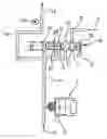
In FIG. 1 a proportional valve 1 is connected to a pilot pressure line 4, which is connected at its free end, i.e., the lower end in FIG. 1, to a pilot pressure supply source which is indicated by an arrow 2. A constant pilot pressure of, for example, 5 bar is provided in pilot pressure line 2 by way of pilot pressure supply source 2.
If the proportional valve is actuated electrically, then the pilot pressure in pilot pressure line 4 can be relieved through proportional valve 1 into a tank 5. Thus, the pilot pressure in pilot pressure line 4 can be lowered specifically to values between 0 and 5 bar with the aid of proportional valve 1.
The other end of pilot pressure line 4, the upper end in FIG. 1, is connected to a servo valve 6 with a spool 7. An additional pressure supply source, indicated by an arrow 9, is connected through a hydraulic line 8 to servo valve 6. The additional pressure supply source supplies a pressure that is significantly greater than a pressure that can be set with the aid of servo valve 6 in a hydraulic line 10, which is also connected to servo valve 6.
Another arrow 12 indicates that the free end of hydraulic line 10, the upper end in FIG. 1, is connected to a servo system. In addition to servo valve 6 with spool 7 and hydraulic line 10, which is also referred to as the servo hydraulic line, the servo system includes, for example, a starting clutch (not shown) that is actuated hydraulically through servo valve 6. The pressure in servo hydraulic line 10 is detected with the aid of a pressure sensor 13.
Spool 7 of servo valve 6 is pressurized with the pilot pressure at one end, in FIG. 1 the left end, through pilot pressure line 4. At its other end, the right end in FIG. 1, spool 7 is relieved or vented into tank 5. Servo valve 6 includes a total of six chambers 14, 15, 17, 18, 19, 20 with connections, which are explained below. Tank 5 is connected to chambers 14, 15. Hydraulic line 8 is connected to chamber 17. Servo hydraulic line 10 is connected to chamber 18. Pilot pressure line 4 is connected to chamber 19. A return line 21 which discharges into servo hydraulic line 10 is connected to chamber 20.
A return surface formed on spool 7 is pressurized via return line 21 and chamber 20. The size of that return surface is coordinated with another pressure surface on spool 7, which is pressurized via chamber 18. Hydraulic line 8 can be connected through servo valve 6 to servo hydraulic line 10 or to tank 5, depending upon the pilot pressure in pilot pressure line 4 that is controlled by proportional valve 1, in order to provide a desired pressure or pressure pattern in servo hydraulic line 10.
In investigations conducted in conjunction with the present invention it has been found that at temperatures in the minus range an undesired delay occurs in converting the electrical control signal of proportional valve 1 to the hydraulic pilot pressure in pilot pressure line 4. The invention provides a way of reducing that undesired time lag between the electrical control signal and the hydraulic response of proportional valve 1, or of eliminating it entirely.
In FIG. 2, the pilot pressure p, in bar, in the pilot pressure line (4 in FIG. 1) and the current I in milliamperes with which the proportional valve (1 in FIG. 1) is actuated are plotted over time t in seconds in a Cartesian coordinate system. The current I is applied in the form of a ramp signal 25 to actuate the starting clutch. The beginning 26 of current ramp signal 25 occurs at about 215 seconds. At point 28 it can be seen that the corresponding pilot pressure ramp signal 29 does not begin until after about 217 seconds. The associated time delay is undesired.
FIG. 3 shows in a similar coordinate diagram how a current ramp signal 35 is applied to the proportional valve (1 in FIG. 1) before the beginning 32 of current ramp signal 35, at 186.56 seconds, through a suitable current impulse 30 which begins after about 186 seconds. As indicated at point 31, current impulse 30 has a value of about 500 milliamperes and lasts about 0.5 seconds. At point 38 it can be seen that the corresponding pilot pressure ramp signal 39 begins at almost the same time, i.e., at 186.60 seconds. The current impulse 30 before the beginning 32 of the change of current ramp signal 35 of the proportional valve enables the response time of the system to be reduced significantly.
According to another aspect of the present invention, the necessary level and duration of control impulse 30 are adapted as a function of the system temperature. With a CVT control that can be done by measuring the actual pressure at the pressure sensor (13 in FIG. 1) during an actuation by a current ramp signal, for example, and comparing it with the same current ramp signal preceded by a current impulse.
An alternative possible solution involves determining the difference between the desired pressure, which can be calculated from the control signal of the proportional valve, and the actual pressure, which can be measured by way of pressure sensor 13. Depending upon that difference, a current impulse or offset can be added to the desired current, which reduces the difference between desired and actual pressure.
Although particular embodiments of the present invention have been illustrated and described, it will be apparent to those skilled in the art that various changes and modifications can be made without departing from the spirit of the present invention. It is therefore intended to encompass within the appended claims all such changes and modifications that fall within the scope of the present invention.
Claims
What is claimed is:1. A method for actuating a hydraulic servo system with the aid of a proportional valve that converts an electrical control signal into a hydraulic pilot pressure with which the hydraulic servo system is actuated, said method comprising the steps of: providing an electrical control signal to the proportional valve, and feeding an additional impulse to the proportional valve at a beginning of a desired change of the electrical control signal.
2. A method in accordance with claim 1, including the step of providing the additional impulse as a current impulse, and adjusting a level and duration of the current impulse as a function of a system temperature.
3. A method in accordance with claim 1, wherein the additional impulse is a square-wave impulse.
4. A method in accordance with claim 1, including the steps of: measuring an actual pressure in the hydraulic servo system when the proportional valve is actuated, and comparing the measured actual pressure with a desired pressure.
5. A method in accordance with claim 4, including the step of feeding the additional impulse to the proportional valve before a desired change of the electrical control signal when a deviation of the actual pressure in the hydraulic servo system from the desired pressure exceeds a predetermined value.
6. A method in accordance with claim 1, including the step of measuring an actual pressure in the hydraulic servo system when the proportional valve is actuated both with and without an additional impulse.
7. A method in accordance with claim 6, including the step of comparing the measured actual pressure values with each other both with and without an additional impulse.
8. A method in accordance with claim 7, including the step of feeding the additional impulse to the proportional valve before a desired change of the electrical control signal when deviations of the measured actual pressure values from corresponding desired values exceed predetermined values.
9. A method in accordance with claim 1, wherein the electrical control signal provided to the proportional valve is a ramp signal.
10. A method in accordance with claim 1, wherein the hydraulic servo system includes at least one of a clutch and a variable speed drive unit of a belt-driven conical-pulley transmission having a variably adjustable transmission ratio.
Images & Drawings included:

Sources:
- United States Patent and Trademark Office - verify current appl. status at the USPTO↗
Similar patent applications:
Recent applications in this class:
- » 20250163941 2025-05-22
Valve - » 20250129804 2025-04-24
THROTTLE DEVICE, FLUID DEVICE AND FLUID SYSTEM - » 20230400042 2023-12-14
Servo valve flapper and nozzle structure - » 20230167834 2023-06-01
Eliminating bleed on flow controls - » 20220228608 2022-07-21
Fluid pressure control device - » 20220196040 2022-06-23
Servo valve flapper and nozzle structure - » 20190309771 2019-10-10
Hydraulic fluid circuit with fixed minimum back pressure - » 20190195245 2019-06-27
Servo valve - » 20190048900 2019-02-14
Pneumatic servovalve assembly - » 20190032683 2019-01-31
Generating two pneumatic signals to operate an actuator on a valve assembly
Recent applications for this Assignee:
- » 20250293624 2025-09-18
METHOD FOR DETERMINING AN INITIAL ROTOR POSITION OF A ROTOR, COMPUTER PROGRAM PRODUCT, CONTROL UNIT, ELECTRIC MACHINE, INSPECTION AND/OR TEST METHOD AND TEST STAND - » 20250290560 2025-09-18
TORQUE CONVERTER WITH PULLING BIAS SPRING - » 20250283516 2025-09-11
FREEWHEEL DEVICE AND FREEWHEEL CLUTCH - » 20250279708 2025-09-04
HYBRID DRIVE RESOLVER ROTOR MOUNTING ARRANGEMENT - » 20250273375 2025-08-28
DETENT SOLENOID - » 20250269726 2025-08-28
Electrical Circuit, On-Board Power Supply System, Vehicle, Method, Computer Program, And Computer-Readable Medium - » 20250269694 2025-08-28
ADJUSTMENT MECHANISM COMPRISING A LINEAR ACTUATOR, VEHICLE AND METHOD FOR OPERATING A VEHICLE - » 20250264157 2025-08-21
PLANETARY GEARBOX HAVING A ROTATIONALLY FIXED THRUST WASHER OF THE PLANET BEARING - » 20250263129 2025-08-21
WHEEL WELL GUARD FOR A WHEEL WELL OF A VEHICLE AND VEHICLE HAVING THE WHEEL WELL GUARD - » 20250262941 2025-08-21
Individual Monitoring Of A Plurality Of Output Points Of A System For The Vehicle-Based Supply Of External Loads