Slip on rail system
US20100258518A1
2010-10-14
12/386,049
2009-04-13
Abstract:
A rail system for organizing rack mountable equipment when the equipment is stacked one piece on top of another. The rail system slides over the flanges of the rack mountable equipment to keep the equipment organized without the need for rack mounting the equipment.
Interested in similar patents?
Get notified when new applications in this technology area are published.
Classification:
H05K7/1404 » CPC main
Constructional details common to different types of electric apparatus; Mounting supporting structure in casing or on frame or rack comprising clamping or extracting means for securing or extracting printed circuit boards by edge clamping, e.g. wedges
H05K7/1404 » CPC main
Constructional details common to different types of electric apparatus; Mounting supporting structure in casing or on frame or rack comprising clamping or extracting means for securing or extracting printed circuit boards by edge clamping, e.g. wedges
A47F5/00 IPC
Show stands, hangers, or shelves characterised by their constructional features
Description
CROSS REFERENCES TO RELATED APPLICATIONS
U.S. patent Documents
U.S. Pat. No. 5,791,498 August 1998 Mills . . . 211/26
U.S. Pat. No. 5,255,832 November 1993 Christensen . . . 224/42.42
U.S. Pat. No. 5,372,262 January 1991 Blum et al . . . 211/182x
STATEMENT REGARDING FEDERAL SPONSORED RESEARCH AND DEVELOPMENT
Not Applicable
REFERENCE TO SEQUENCE LISTING
Not Applicable
BACKGROUND OF THE INVENTION
This Invention relates to 19″ Rack mount equipment (EIA 310-D).
In situations where the equipment is not mounted in a rack, but where multiple units are stacked on top of each other. When they are stacked they become unstable and slide around, becoming unorganized. This invention keeps them organized and stable.
BRIEF SUMMARY OF THE INVENTION
This invention is a slip on rail system for rack mount equipment or any equipment witch has side flanges. It allows the equipment to be used without mounting an a rack. The apparatus keeps the equipment organized and stable. The slip on rail system is a channeled tensioning device to grasp the flanges on the sides of the equipment.
BRIEF DESCRIPTION OF THE SEVERAL VIEWS OF THE DRAWINGS
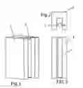
FIG. 1 is a perspective view of the front and side with tension device showing.
FIG. 2 is a top view of the tension device showing.
FIG. 3 is a side view with tension device showing.
FIG. 4 is a top view installed on rack mount equipment.
FIG. 4a is a detailed top view as it would be used to hold rack mount equipment.
FIG. 5 is a front view with dotted lines showing equipment flanges.
FIG. 6 is front view with dotted lines showing depth on channel
DETAILED DESCRIPTION OF THE INVENTION
Referring to FIG. 1 in conjunction with FIG. 2 and FIG. 3 the slip on rail 1 is made from material with a channel into which the rack mount equipment 3 flanges are inserted and are retained by a tensioning device 2. other material rigid enough to keep the rack mounted equipment in place. The tensioning device 2 can be made from an elastic or spring material that is attached or retained in the channel.
Referring to FIG. 4a in conjunction with FIG. 4 and FIG. 5 as well as FIG. 6 shows how the slip on rail system 1 would fit on the equipment 3 during use.
The preferred embodiment is as shown in FIGS. 1, 2, and 3 in which the tensioning device 2 is a circular cross-section vinyl gasket with retention barb.
Claims
1. This invention is a slip on rail system for holding rack mount equipment or any equipment with mounting flanges together when used without putting them in a rack.
Images & Drawings included:


Sources:
- United States Patent and Trademark Office - verify current appl. status at the USPTO↗
Similar patent applications:
Recent applications in this class:
- » 20250081374 2025-03-06
THERMALLY CONDUCTIVE CIRCUIT CARD GUIDES - » 20240389255 2024-11-21
Locking bracket and chasis - » 20240040730 2024-02-01
DETACHING MECHANISM FOR A DETACHABLE MODULE AND ELECTRONIC DEVICE THEREWITH - » 20230262917 2023-08-17
Heat transfer interfaces for circuit card assembly (CCA) modules - » 20210352818 2021-11-11
Facilitated expansion card removal - » 20210315120 2021-10-07
Wedge lock support columns in electronic chassis - » 20210105907 2021-04-08
Vehicle circuit card assembly - » 20200260606 2020-08-13
Faceplate and electronic device - » 20200029454 2020-01-23
Double line replaceable module locking bracket - » 20190230808 2019-07-25
Two-phase fluid-actuated cooling device, system, and method