Method and device for influencing the traction force during shifting operations of a manual transmission in vehicles
US20100280720A1
2010-11-04
12/733,642
2008-09-10
✅ Patent granted
US 8,401,748 B2
2013-03-19
WO; PCT/EP2008/061973; 20080910
WO; WO2009/037158; 20090326
James Trammell | Majdi Alsomiri
Kenyon & Kenyon LLP
2029-03-08
Abstract:
In a method for influencing the traction force during shifting operations of a manual transmission in vehicles having at least two drive axles, the drive system of the first axle is activated in such a way that the interruptions in traction force occurring at the second axle during shifting operations of the manual transmission are at least partially compensated for.
Assignee:
- Robert Bosch GMBH 19,123 🇩🇪 Stuttgart, Germany
Applicant:
Interested in similar patents?
Get notified when new applications in this technology area are published.
Classification:
F16D13/04 IPC
Friction clutches with means for actuating or keeping engaged by a force derived at least partially from one of the shafts to be connected
E01B9/303 » CPC main
Fastening rails on sleepers, or the like; Fastening rails, tie-plates, or chairs directly on sleepers or foundations; Means therefor; Fastening on wooden or concrete sleepers or on masonry with clamp members by resilient steel clips the clip being a shaped bar
E01B9/38 » CPC further
Fastening rails on sleepers, or the like Indirect fastening of rails by using tie-plates or chairs; Fastening of rails on the tie-plates or in the chairs
E01B9/66 » CPC further
Fastening rails on sleepers, or the like Rail fastenings allowing the adjustment of the position of the rails, so far as not included in the preceding groups
B60L2200/26 » CPC further
Type of vehicles Rail vehicles
B60L9/00 IPC
Electric propulsion with power supply external to the vehicle
G06F7/00 IPC
Methods or arrangements for processing data by operating upon the order or content of the data handled
B60T7/12 IPC
Brake-action initiating means for automatic initiation; for initiation not subject to will of driver or passenger
B60T8/24 IPC
Arrangements for adjusting wheel-braking force to meet varying vehicular or ground-surface conditions, e.g. limiting or varying distribution of braking force responsive to vehicle inclination or change of direction, e.g. negotiating bends
B60K6/20 IPC
Arrangement or mounting of plural diverse prime-movers for mutual or common propulsion, e.g. hybrid propulsion systems comprising electric motors and internal combustion engines the prime-movers consisting of electric motors and internal combustion engines, e.g. HEVs
B60K17/354 IPC
Arrangement or mounting of transmissions in vehicles for driving both front and rear wheels, e.g. four wheel drive vehicles having separate mechanical assemblies for transmitting drive to the front or to the rear wheels or set of wheels
F01B23/00 IPC
Adaptations of machines or engines for special use; Combinations of engines with devices driven thereby
F16D11/04 IPC
Clutches in which the members have interengaging parts disengaged by a contact of a part mounted on the clutch with a stationarily-mounted member with clutching members movable only axially
F16D13/60 IPC
Friction clutches; Details Clutching elements
Description
BACKGROUND OF THE INVENTION
1. Field of the Invention
The present invention is directed to a method and a device for influencing the traction force during shifting operations of a manual transmission in vehicles.
2. Description of Related Art
Many vehicles are equipped with two axles, only one of which is usually driven. This axle is often connected to an internal combustion engine via a manual transmission and a clutch. Manual transmissions frequently have the characteristic that they must be shifted without load. For this purpose, the internal combustion engine is disconnected from the remainder of the drive train by disengaging the clutch. No traction force can be transmitted via the clutch as long as it is disengaged. As a result, an interruption in the traction force occurs during shifting operations for a manual transmission. Due to the equation F=m*a, the traction force is a direct measure of the occurring vehicle acceleration. A drop in traction force is therefore also always a drop in the vehicle acceleration. A sudden drop or increase in the vehicle acceleration is perceived as a jerk by an occupant of a vehicle. A hybrid motor vehicle drive is known from German patent document DE 3542059 C1 in which the two wheels of a drive axle are driven by an internal combustion engine via a transmission having a variable transmission ratio, and the vehicle wheels on a different drive axle may be driven by one or more electric machines.
BRIEF SUMMARY OF THE INVENTION
The present invention is directed to a method and a device for influencing the traction force during shifting operations of a manual transmission in vehicles. The essence of the present invention is that the comfort during shifting may be increased in vehicles having drive systems which act on different axles. This is achieved by at least partially compensating for the interruption in traction force which occurs during a shifting operation when a drive system is disconnected from the drive axle by disengaging the clutch. For this purpose, by use of the device according to the present invention a drive system on a further axle is activated in such a way that the interruption in traction force is at least partially compensated for. The acting traction force usually has different values before and after the shifting operation. When a shift is made to a higher gear, the traction force directly before the shifting operation is higher than directly after the shifting operation, since the transmission ratio is smaller in the higher gear. When a shift is made to a lower gear, the traction force after shifting is correspondingly higher than before shifting. The particular value of the traction force before and after shifting is referred to below as the “traction force level.”
Thus, by use of the device according to the present invention not only is the interruption in traction force at least partially compensated for, but also a transition from the traction force level before shifting to the traction force level after shifting is implemented.
Advantageous refinements of and improvements on the device described in the independent claim are possible using the measures stated in the dependent claims.
The gradient of the traction force during the shifting operations may advantageously be predefined. Thus, for example, the driver's input, for example for a torque requested for acceleration of the vehicle via the gas pedal, may be directly implemented.
A further advantageous embodiment of the present invention provides for carrying out the activation in the sense of a higher vehicle acceleration. For example, the duration of the acceleration until reaching the maximum speed may thus be minimized.
A further advantageous embodiment of the present invention provides that the drop and subsequent increase in the vehicle acceleration caused by the interruption in traction force, and in particular the associated perceivable jerk, during shifting operations is minimized by minimizing the slope of the traction force gradient between the two traction force levels.
In a particularly advantageous manner the gradient of the traction force during the shifting operation is controlled in such a way that limiting values for modifying the vehicle acceleration are not exceeded.
A further advantageous embodiment of the present invention provides that the traction force varies according to the driver's input, even during the shifting operations. Thus, for example, the vehicle acceleration may be controlled according to the driver's input even during the shifting operation.
In reality, the torques on the drive system which are necessary for setting the traction force levels before and after the shifting operation are set with a certain time delay, for example because of dead time in the drive systems. Therefore, in a further advantageous embodiment of the present invention it is provided that the activation of the clutch after a shifting request is accordingly delayed so that disconnection of the corresponding torques, or a switch of the torques acting on the two drive axles, is ensured to the greatest extent possible without a drop or increase in the vehicle acceleration, and in particular without the associated perceivable jerk.
BRIEF DESCRIPTION OF THE SEVERAL VIEWS OF THE DRAWING
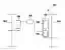
FIG. 1 shows a device for influencing the traction force during shifting operations of a manual transmission in vehicles.
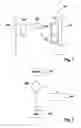
FIG. 2 shows a method for at least partially compensating for interruption in the traction force during shifting operations in vehicles.
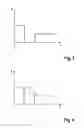
FIG. 3 shows a traction force gradient during shifting, without compensation.
FIG. 4 shows a traction force gradient during shifting, with compensation.
DETAILED DESCRIPTION OF THE INVENTION
FIG. 1 shows a device 105 for influencing the traction force during shifting operations of a manual transmission 102 in vehicles 101. Two drive axles 103, 104 are provided for the vehicle. Drive system 106 is provided for drive axle 103. In this specific embodiment drive system 106 is designed as an electric machine. Drive system 107 is provided for drive axle 104. In this specific embodiment this drive system is composed of an internal combustion engine 108 and manual transmission 102. Control unit 105 is electronically connected to each of drive systems 106 and 107, thus enabling bidirectional data and signal transmission.
FIG. 2 shows a method for at least partially compensating for interruptions in traction force during shifting operations in vehicles. In method step 202 a check is made as to whether a shifting operation should be carried out. If no shifting operation is to be carried out, the method ends with method step 204. If a shifting operation is to be carried out, the method branches to method step 203. In method step 203
the instantaneous traction force is determined,
the traction force after the shifting operation is computed, and
a traction force gradient is computed for the transition from the instantaneous traction force to the traction force after the shifting operation.
During the shifting operation a further drive is activated in such a way that this drive compensates for the interruption in traction force caused by the shifting operation, according to the computed traction force gradient. After the shifting operation is completed the method ends with method step 204. The referenced steps may be cyclically repeated and processed.
FIG. 3 shows the traction force gradient during a shifting operation, without compensation. The traction force is plotted over time in the illustration. Before the shifting operation begins the traction force is at a high level. During the shifting operation the drive system is disconnected from the drive axle via a clutch, thus preventing transmission of traction force. After the shifting operation is completed the clutch is re-engaged, and once again a traction force acts corresponding to the instantaneous torque and the transmission ratio.
In the description below the terms have the following meanings:
M_prim: active torque, primary drive
M_sec: active torque, secondary drive
i_prim_old: effective transmission ratio before shifting
i_prim_new: effective transmission ratio after shifting
i_sec: effective transmission ratio, secondary drive
F: resulting traction force
The following applies in general for the traction force:
F=M_prim*i_prim+M_sec*i_sec.
During shiftings the clutch is disengaged, and it is not possible to transmit traction force via the primary drive. In this case the following applies:
F=M_sec*i_sec.
The effective torques are determined by the driver's input. In the simplest case the traction force is applied only by the primary drive, and the secondary drive makes no contribution. Likewise, the driver's input is assumed to be constant, and therefore the primary drive torque in the time period for shifting is also assumed to be constant. The change in transmission ratio as a result of the shifting causes a deviation in the traction force before and after shifting.
Situation before shifting:
F_old=M_prim*i_prim_old
Situation after shifting:
F_new=M_prim*i_prim_new
Situation during shifting:
F_shift=M sec*i_sec
Traction force F shift may be influenced during shifting by suitable selection of the torque of secondary drive M_sec. For complete compensation of traction force F_old during shifting, this results in
F_shift=F_old and thus M_sec=M_prim*i_prim old/i_sec.
If time period t_shift for the shifting is known, secondary drive M_sec may also be selected in such a way that the most linear transition possible between F_old and F_new is achieved. The following expression is then valid:
F_shift (t)=F_old+t*(F_new-F_old)/t_shift.
From this expression M_sec may in turn be computed:
M sec (t)=M_prim*(i_prim_old+t/t_shift*(i_prim_new-i_prim_old))/i_sec.
FIG. 4 shows a traction force gradient during a shifting operation, with compensation. The traction force is plotted over time in the illustration. The solid line represents the traction force gradient at the axle to which the manual transmission is flange-mounted. During the shifting operation it is not possible for traction force to be transmitted to this axle. The gradient is comparable to that from FIG. 3. The dash-dotted line represents the traction force gradient at the other axle on which the other drive system acts. Thus, the traction force is at least partially compensated for during the shifting operation. The transition of the traction force from the high level before the shifting operation to the low level after the shifting operation is achieved by activating the second drive system. Depending on the activation of the second drive system, it is possible to implement a discontinuous, linear, or also a freely selectable transition.
Claims
1-8. (canceled)
9. A device for influencing the traction force of a vehicle having at least two axles during a shifting operation of a manual transmission in the vehicle, comprising:
a control unit configured to activate a drive system for a first axle of the vehicle during the shifting operation in such a way that an interruption in traction force occurring at a second axle of the vehicle during the shifting operation of the manual transmission is at least partially compensated.
10. The device as recited in claim 9, wherein the control unit is configured to activate the drive system of the first axle during the shifting operation in such a way that a traction force gradient during the shifting operation occurs in a predefined manner.
11. The device as recited in claim 10, wherein the control unit is configured to activate the drive system of the first axle during the shifting operation to produce a high traction force.
12. The device as recited in claim 10, wherein the drive system of the first axle is activated during the shifting operation to produce a low degree of variation in the traction force.
13. The device as recited in claim 10, wherein the traction force gradient during the shifting operation occurs in such a way that at least one limiting value for modifying the traction force is not exceeded.
14. The device as recited in claim 10, wherein the traction force gradient occurs as a function of a driver's input detected during the shifting operation.
15. The device as recited in claim 9, wherein the control unit is configured to delay an activation of a clutch in response to a shifting request so that a switch of torques acting on the two drive axles is maximized without substantial variation in the traction force.
16. A method for at least partially compensating for an interruption in traction force of a vehicle having at least two axles during a shifting operation of a manual transmission in the vehicle, comprising:
activating a drive system for a first axle of the vehicle during the shifting operation in such a way that an interruption in traction force occurring at a second axle of the vehicle during the shifting operation of the manual transmission is at least partially compensated.
Images & Drawings included:
Sources:
- United States Patent and Trademark Office - verify current appl. status at the USPTO↗
Recent applications in this class:
- » 20210230809 2021-07-29
Boltless fastener assembly for heavy haul railway with axle load of 35-40 tons - » 20190284765 2019-09-19
Tension Clamp, Guide Plate and Fastening Point for Securing a Rail to a Ground Surface - » 20190242067 2019-08-08
SCREWED FASTENING SYSTEM FOR RAILWAY RAILS - » 20170226701 2017-08-10
Railway rail fastening clip and pad for recessed railseats - » 20150176223 2015-06-25
Railway rail fastening clip and pad for recessed railseats - » 20120187206 2012-07-26
System for fastening a rail in place and fastening for a rail - » 20120187203 2012-07-26
SEALING PLATE FOR USE WITH RAIL CLIP ANCHORING DEVICE - » 20120181344 2012-07-19
Insulator for railway fastening clip and railway rail fastening clip for use therewith - » 20120111960 2012-05-10
Tensioning clamp for fastening a rail and system equipped with a tensioning clamp of this type - » 20120111959 2012-05-10
Rail clamp for attaching a rail and system provided with a rail clamp of this type
Recent applications for this Assignee:
- » 20250154889 2025-05-15
PRESSURE CONTROL IN AN EXHAUST AFTERTREATMENT SYSTEM - » 20250154580 2025-05-15
ENZYME TRANSLOCATORS IN NANOGAP WITH 3' -ESTERS - » 20250147582 2025-05-08
METHOD FOR DETERMINING AN EYE DISTANCE IN A PAIR OF DATA GLASSES, AND DATA GLASSES - » 20250146568 2025-05-08
DRIVE ASSEMBLY AND VEHICLE HAVING SUCH A DRIVE ASSEMBLY - » 20250146495 2025-05-08
Flexible Pump Assembly for Use in a Fan Drive - » 20250140882 2025-05-01
FUEL CELL SYSTEM HAVING ENERGY RECUPERATION - » 20250137810 2025-05-01
METHOD FOR MATCHING A DIGITAL ROAD MAP - » 20250137033 2025-05-01
DNA UNFOLDING USING A FREE-END TAG FLOW MODIFIER - » 20250119751 2025-04-10
A BLUETOOTH COMMUNICATION METHOD AND SYSTEM - » 20250118116 2025-04-10
Diagnostic Protocol Search With Improved Efficiency