Valve component
US20100288961A1
2010-11-18
12/671,673
2008-08-01
✅ Patent granted
US 9,334,986 B2
2016-05-10
WO; PCT/EP2008/006359; 20080801
WO; WO2009/015900; 20090205
Terry Cecil
Knobbe Martens Olson & Bear LLP
2029-01-20
Abstract:
For the simple and cost-effective production of a valve component (1) in the form of a non-return valve or a connecting nipple, in particular for the refuelling of natural gas vehicles, or for the pressure-tight connection to a fluid line or a plug-in coupling, wherein the valve component (1) has two housing parts (3, 4) which are connected pressure-tightly to each other and accommodate a valve (7) there within, it is proposed that the housing parts (3, 4) are pressed together at an annular groove (3′).
Applicant:
Interested in similar patents?
Get notified when new applications in this technology area are published.
Classification:
F16L13/141 » CPC main
Non-disconnectible pipe-joints, e.g. soldered, adhesive or caulked joints made by plastically deforming the material of the pipe, e.g. by flanging, rolling by crimping or rolling from the outside
F16K15/026 » CPC further
Check valves with guided rigid valve members the valve being loaded by a spring the valve member being a movable body around which the medium flows when the valve is open
F16K15/063 » CPC further
Check valves with guided rigid valve members with guided stems the valve being loaded by a spring
F16L29/02 » CPC further
Joints with fluid cut-off means with a cut-off device in one of the two pipe ends, the cut-off device being automatically opened when the coupling is applied
F16K25/005 » CPC further
Details relating to contact between valve members and seat Particular materials for seats or closure elements
F17C2205/037 » CPC further
Vessel construction, in particular mounting arrangements, attachments or identifications means; Fluid connections, filters, valves, closure means or other attachments; Fittings, valves, filters, or components in connection with the gas storage device Quick connecting means, e.g. couplings
F16K27/00 IPC
Construction of housing ; Use of materials therefor
F16L13/14 IPC
Non-disconnectible pipe-joints, e.g. soldered, adhesive or caulked joints made by plastically deforming the material of the pipe, e.g. by flanging, rolling
F16K15/02 IPC
Check valves with guided rigid valve members
F16K15/06 IPC
Check valves with guided rigid valve members with guided stems
F16K25/00 IPC
Details
F16K25/00 IPC
Details relating to contact between valve members and seat
Description
The invention relates to a valve component in form of a non-return valve or a connection fitting, in particular for the refuelling of natural gas vehicles, according to the preamble of claim 1,
Such a connection fitting is known from WO 00/52378 of the Applicants. Therein a quick-connect coupler is described, which can be connected to the connection fitting, wherein collets engage in the connection fitting. Thus, a coupling and pressure-tight connection is achieved, as this is required for the pressurized refuelling of natural gas vehicles with relative high pressure. The connection fitting is exposed to rather high loads, such that it has to be very stable, in order to be in line with the standards for the natural gas refuelling (NGV).
Such connection fittings are usually screwed together from two capsule-shaped housing parts, in which a valve is inserted with corresponding sealing surfaces. However, this concept is relatively expensive, since the manufacture of outer and internal threads is very expensive, and in addition several O-rings in corresponding grooves are required to seal the housing parts to each other and the inserted valve. Thus, assembly expenditure is rather high, as well.
Thus, the invention intends to create a valve component being simplified in manufacturing and therefore inexpensive.
This object is achieved by a valve component in accordance with the features of claim 1. Preferred embodiments are subject matter of the dependent claims.
By the suggested press-fitting of the two housing parts of the valve component, in particular in form of a connection fitting, it is possible to connect this without expensive threads in a safe and pressure-tight way. Thus, significant cost saving is possible. Besides significant cost saving it is possible to use only a single seal bushing instead of several O-rings. In particular, a safe sealing surface is provided by the use of a seal bushing at the joint or interface between the housing parts and at the same time a sealing surface for the incorporated valve is formed, such that a double function results. Thus, assembly is substantially simplified, so that assembling can be done e.g. by a robot, as well.
In a preferred embodiment the seal bushing is formed from a resistant plastic, preferably from PEEK, since this results in the required tong-term tightness. Further to the sealing of a non-return valve in the connection fitting also a filter insert can be safely fixed, which especially follows adjacent to the seal bushing. Thus, a very compact structure of the connection fitting and/or the valve component is achieved.
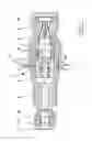
Subsequently, a preferred embodiment of the valve component, in particular in form of a connection fitting or a check valve is described and explained on the basis of the drawings. They show in: FIG. 1 a half-section of a valve component in form of a connection fitting, and FIG. 2 a check valve designed in a similar way.
FIG. 1 shows a sectional view of a valve component 1 in form of a connection fitting. The connection fitting has a connection profile 2, e.g. for a plug-on quick-connect coupler, to be connected to the pressure-tight terminal of a quick-connect coupler, shown in EP 1 271 039 of the Applicants. The valve component 1 consists of two main parts, i.e. two capsule-shaped housing parts 3 and 4, which are safely connected with one another by a grouting or press-fitting (as indicated by arrow 5), For this purpose an annular groove 3′ is provided in one of the housing parts (here the left part 3), into which a bead 5′ (shown in the bottom half as dash line) is pressed after putting-over the housing part 4. Thus, the two housing parts 3 and 4 are stably and safely connected with the press-fitting or grouting 5.
This grouting 5 also fixes a seal bushing 8 which is arranged at the joint or interface of the two housing parts 3 and 4 inside the connection fitting and which is preferably pressed into one of the two housing parts. Thus, a safe seal to the outside is achieved. In addition, the seal bushing 8 also serves as contact or sealing surface for an incorporated valve 7, namely a check or non-return valve. Check valve 7 has a conical nipple 7′, which contacts the seal bushing 8 serving as sealing surface and is supported in a telescope element 6 with a closing spring 6′. On pressurization, in particular with the refuelling, the conical nipple 7′ can evade by the sliding movement against the spring 6′ in the telescope element 6, here to the left, thus releasing the fluid passage to a connected tube, which is fixed e.g. by a nut 11 and sealing sections 12, 13 and leads to a natural gas reservoir.
in a preferred embodiment a filter insert 9 is positioned adjacent to the seal bushing 8, in particular in direct contact. The filter insert 9 has here a tapered outer shape, so that the tip of the filter insert 9 extends to a sealing ring 10, which is inserted in an interior groove inside the connection profile 2. This sealing ring 10 contacts a sealing piston of a quick-connect coupler (not illustrated) in the connection position, so that a pressure-tight attachment results. In this connected position collets (or balls as known from hydraulic couplings) engage with the connection profile 2, Such a structure of the quick-connect coupler is exemplified in WO 00/52378 of the Applicants, as initially specified. Altogether a very simple and variable connection fitting is provided, in particular for a refuelling nipple of natural gas vehicles.
FIG. 2 shows the configuration of a check valve, wherein members of the same function are referred to with the same reference numerals as in FIG. 1. By the absence of the elongated connection profile 2 and the filter insert 9 the valve component 1 is even more compact. The nut 11 with the sealing sections 12, 13 to a fluid line Is here provided at the right half. The housing parts 3 and 4, as well as the grouting 5 (by pressing the bead 5′ into the annular groove 3′, preferably by means of a hose press) are similar to FIG. 1. The same applies to the seal bushing 8, which preferably consists of a resistant polyether-etherketone (PEEK). This material offers a high tightness even at extreme temperatures below freezing and medium stability, which can lead to problems with conventional O-rings. As material for the housing parts 3 and 4 it is recommendable to use a ductile, cold-deformable material for the housing part with the bead 5′ to be pressed into the housing part (here 3) with the ring groove 3′, being formed of high-strength steel, Thus, the press-fitting 5 can be manufactured with relative small energy.
Claims
1. A valve component in a form of a non-return valve or a connecting nipple, wherein the valve component has two housing parts which are connected pressure-tightly to one another and accommodate a valve therein, wherein the housing parts are pressed together at an annular groove.
2. A valve component according to claim 1, wherein a seal bushing is arranged inside at the joint between the housing parts and further forms the sealing surface for the valve.
3. A valve component according to claim 2, wherein the seal bushing is pressed into one of the housing parts.
4. A valve component according to claim 3, wherein a filter insert follows in axial direction to the seal bushing and is pressed together with the seal bushing into one of the housing parts.
5. A valve component according to claim 4, wherein the filter insert has a tapered outer shape.
6. A valve component according claim 2, wherein the seal bushing comprises plastic.
7. A valve component according to claim 1, wherein a hose press is used for press-fitting, in particular of a projecting bead into the annular groove.
8. A valve component according to claim 6, wherein the plastic is polyetheretherketone (PEEK).
Images & Drawings included:


Sources:
- United States Patent and Trademark Office - verify current appl. status at the USPTO↗
Similar patent applications:
- » 20200018421
Diaphragm valves, valve components, and methods for forming valve components - » 20190024803
Valve component arrangement and a control valve with a valve component arrangement - » 20200355296
DIAPHRAGM VALVES, VALVE COMPONENTS, AND METHODS FOR FORMING VALVE COMPONENTS - » 20090078828
ANTI-ICE VALVE COMPONENTS AND METHODS OF COUPLING A VALVE ASSEMBLY TO A SERVO CONTROLLER OF ANTI-ICE VALVE COMPONENTS - » 20210299424
VALVE COMPONENT AND VALVE ASSEMBLY - » 20170056162
Prosthetic valve system having a docking component and a prosthetic valve component - » 20170128202
Valve component, frame component and prosthetic valve device including the same for implantation in a body lumen - » 20180243088
Valve component, frame component and prosthetic valve device including the same for implantation in a body lumen - » 20140075756
Intravascular valve component with improved valve positioning - » 20150073543
Valve component, frame component and prosthetic valve device including the same for implantation in a body lumen
Recent applications in this class:
- » 20250164044 2025-05-22
EXHAUST PIPE JOINT - » 20250122960 2025-04-17
COLOR CHANGING CRIMP RING DEVICE - » 20240410501 2024-12-12
CRIMPED JOINTS FOR CLIMATE CONTROL SYSTEMS - » 20230287997 2023-09-14
Pipe connection apparatus - » 20230160503 2023-05-25
METHODS AND APPARATUS FOR USING CRIMP RINGS ON FLEXIBLE TUBING - » 20220003341 2022-01-06
Pipe, spool forming die, and pipe manufacturing method - » 20210332916 2021-10-28
HYDRAULIC SEALING BODY FOR BICYCLE BRAKING SYSTEMS AND HYDRAULIC HOSE ASSEMBLY FOR BICYCLE BRAKING SYSTEMS - » 20210254762 2021-08-19
Fitting for connection to at least one pipe - » 20210148492 2021-05-20
Stepped pipe member and stepped pipe member production method - » 20210062942 2021-03-04
Pressing tool and method for a re-pressing operation