FEEDBACK SYSTEM FOR OPTIMIZING EXPOSURE
US20100289942A1
2010-11-18
12/556,084
2009-09-09
Abstract:
A processor disposed inside of a display device analyzes the image received by a camera mounted on the display device to determine the optimum output intensity of a light source also mounted on the display device.
Inventors:
- Robert Hardacker 80 🇺🇸 Escondido, CA, United States
- Rafael Calderon 15 🇺🇸 San Diego, CA, United States
- STEVEN RICHMAN 50 🇺🇸 SAN DIEGO, CA, United States
Interested in similar patents?
Get notified when new applications in this technology area are published.
Classification:
H04N1/00347 » CPC main
Scanning, transmission or reproduction of documents or the like, e.g. facsimile transmission; Details thereof; Connection or combination of a still picture apparatus with another apparatus, e.g. for storage, processing or transmission of still picture signals or of information associated with a still picture with another still picture apparatus, e.g. hybrid still picture apparatus
G06F3/147 » CPC further
Input arrangements for transferring data to be processed into a form capable of being handled by the computer; Output arrangements for transferring data from processing unit to output unit, e.g. interface arrangements; Digital output to display device ; Cooperation and interconnection of the display device with other functional units using display panels
H04N1/0035 » CPC further
Scanning, transmission or reproduction of documents or the like, e.g. facsimile transmission; Details thereof User-machine interface; Control console
H04N21/41407 » CPC further
Selective content distribution, e.g. interactive television or video on demand [VOD]; Client devices specifically adapted for the reception of or interaction with content, e.g. set-top-box [STB]; Operations thereof; Structure of client; Structure of client peripherals; Specialised client platforms, e.g. receiver in car or embedded in a mobile appliance embedded in a portable device, e.g. video client on a mobile phone, PDA, laptop
H04N21/42202 » CPC further
Selective content distribution, e.g. interactive television or video on demand [VOD]; Client devices specifically adapted for the reception of or interaction with content, e.g. set-top-box [STB]; Operations thereof; Structure of client; Structure of client peripherals; Input-only peripherals , e.g. global positioning system [GPS] environmental sensors, e.g. for detecting temperature, luminosity, pressure, earthquakes
H04N21/4223 » CPC further
Selective content distribution, e.g. interactive television or video on demand [VOD]; Client devices specifically adapted for the reception of or interaction with content, e.g. set-top-box [STB]; Operations thereof; Structure of client; Structure of client peripherals; Input-only peripherals , e.g. global positioning system [GPS] Cameras
H04N21/4318 » CPC further
Selective content distribution, e.g. interactive television or video on demand [VOD]; Client devices specifically adapted for the reception of or interaction with content, e.g. set-top-box [STB]; Operations thereof; Processing of content or additional data, e.g. demultiplexing additional data from a digital video stream; Elementary client operations, e.g. monitoring of home network or synchronising decoder's clock; Client middleware; Generation of visual interfaces for content selection or interaction ; Content or additional data rendering by altering the content in the rendering process, e.g. blanking, blurring or masking an image region
G09G2310/0232 » CPC further
Command of the display device; Addressing, scanning or driving the display screen or processing steps related thereto Special driving of display border areas
G09G2320/0626 » CPC further
Control of display operating conditions; Adjustment of display parameters for control of overall brightness
G09G2320/0666 » CPC further
Control of display operating conditions; Adjustment of display parameters for control of colour parameters, e.g. colour temperature
G09G2330/022 » CPC further
Aspects of power supply; Aspects of display protection and defect management; Details of power systems and of start or stop of display operation; Power management, e.g. power saving in absence of operation, e.g. no data being entered during a predetermined time
G09G2354/00 » CPC further
Aspects of interface with display user
G09G2360/144 » CPC further
Aspects of the architecture of display systems; Detecting light within display terminals, e.g. using a single or a plurality of photosensors the light being ambient light
G09G2380/16 » CPC further
Specific applications Digital picture frames
H04N5/58 » CPC further
Details of television systems; Receiver circuitry for the reception of television signals according to analogue transmission standards; Control of contrast or brightness in dependence upon ambient light
H04N5/225 IPC
Details of television systems; Studio circuitry; Studio devices; Studio equipment ; Cameras comprising an electronic image sensor, e.g. digital cameras, video cameras, TV cameras, video cameras, camcorders, webcams, camera modules for embedding in other devices, e.g. mobile phones, computers or vehicles Television cameras ; Cameras comprising an electronic image sensor, e.g. digital cameras, video cameras, camcorders, webcams, camera modules specially adapted for being embedded in other devices, e.g. mobile phones, computers or vehicles
H04N5/57 IPC
Details of television systems; Receiver circuitry for the reception of television signals according to analogue transmission standards Control of contrast or brightness
H04N5/66 IPC
Details of television systems Transforming electric information into light information
H04N9/64 IPC
Details of colour television systems Circuits for processing colour signals
Description
This claims priority from U.S. provisional patent application Ser. No. 61/179,304, filed May 18, 2009.
I. Field of the Invention
The present invention relates a feedback system implemented into a display device involving a mounted light source whose brightness is controlled by a mounted camera sending information to a processor within the display device.
II. Background of the Invention
Methods of communication have evolved over centuries to its present state of efficiency and affordability. The prior art includes communication devices that allow two (or more) parties to speak in real time and observe each other via cameras and display screens. Sound and picture information may be sent over the internet or wirelessly, i.e. via wireless communication devices utilizing radio signals gathered by antennas on the receiving end.
Lighting determines the contrast and hence quality of a picture or video captured by a camera. Exceedingly bright light results in overexposure and poor image quality, sometimes known as whiteout. Conversely, an insufficient amount of light underexposes the image resulting in a dark image. To date, no prior art has proposed a method of automatically controlling picture exposure.
SUMMARY OF THE INVENTION
The present invention aims to control picture exposure by means of a feedback system. A processor within the display device uses colorimetry to analyze a picture captured by a camera in real time and control the intensity of light being outputted by a light source mounted on or within the display device. This ensures proper exposure and optimum picture quality being captured by the camera.
Accordingly, in one aspect a system includes a video display, a light source associated with the display for projecting light onto a user of the display who is facing the display, and a camera positioned to image a user facing the display. A processor that may control the display receives signals from the camera and responsive thereto establishes an output of the light source.
The camera may be mounted on the display whereas the light source may be mounted on an edge of the display or inside a bezel of the display. The processor can use colorimetry information from the camera to establish the output of the light source, which output may be, e.g., brightness and/or color temperature.
In another aspect, a method includes imaging a user of a video display associated with a light source illuminating the user, and based on the imaging act, establishing an indicia of illumination of the light source to achieve a desired illumination of the user.
In another aspect, a system has a video display, a light source projecting light onto a user of the display who is facing the display, and an imager positioned to image a user facing the display. A processor receives signals from the imager and responsive thereto establishes an output hue, and/or a brightness, of the light source.
BRIEF DESCRIPTION OF THE DRAWINGS
FIG. 1 is a perspective view of a display device, showing interior components systematically,
FIG. 2 is an anterior view of a display device illustrating possible camera and light source configuration.
FIG. 3 is a side view of a display device (exterior shell is shown to be transparent) and its user to illustrate the arrangement of the system including camera and light source.
DETAILED DESCRIPTION OF THE PREFERRED EMBODIMENT
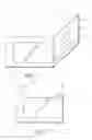
Referring initially to FIG. 1, a display device 10 includes a video display screen 12 and bezel casing 14. The display device may be, but is not limited to, a computer laptop or TV. The display screen 12 may be an LCD display or any other mode of display screen. The bezel 14 may be comprised of plastic; however it is not limited to a plastic medium. Interior components are shown and include a tuner 16, medium 18, and microprocessor 20. These internal constituents are shown to present functioning aspects of the display device, however are not limited to the tuner 16, medium 18, and processor 20. The processor 20 controls the output of an image presented on the display screen.
Moving in reference to FIG. 2, an anterior perspective of the display device 10 is shown with a front view of the display screen 12 and bezel casing 14. A camera 22 is mounted on the bezel 14 in a forward facing position enabling image capture of objects, particularly the display device user, in front of the display device 10. The camera 22 may comprise a casing of various shapes and mediums and its mounting configuration in relation to the display device 10 is not limited to that which is shown. A light source 24 is shown to be mounted on the bezel 14 in the upper right hand corner of the display device 10.
The light source 24 may be mounted on the edge of the display device 10 or disposed within the bezel 14. Various light intensities are capable of being outputted by the light source 24. Further, the light source 24 is turned on when the camera 22 is activated and may be, but is not limited to, white LED lights suitable for human colorimetry.
Another variation of the light source 24 could employ different color LEDs with independent control to optimize not only the lumen level, but also the color temperature of the lighting source and hence the person. In such an embodiment the hue is effectively controlled by controlling the illumination of red, green and blue LEDs in the light source.
Now referring to FIG. 3, a side view of the display device 10 and a display device user 26 is shown to illustrate a two dimensional perspective of the user 26 being in front of the display device 10. The bezel 14 is shown to be transparent (dotted lines) to enable viewing of internal components including the tuner 16, medium 18, and processor 20. The camera 22 and light source 24 are also shown in a configuration similar to that of FIG. 2. The light source 24 illuminates the face of the user 26.
In addition to controlling the picture imaged on the display screen, the processor 20 receives signals from the camera 22 and responds by varying the light intensity, or brightness, and/or the color temperature of the light being outputted by the light source 24 to optimize, from a colorimetry standpoint, the image captured by the camera. The processor 20 uses colorimetry to analyze the amount of illumination on the face of the user 26 from the camera 22 and determine the output of the light source 24 in terms of brightness. The dotted lines with arrows demonstrate the light waves leaving the light source 24, bouncing of the face of the user 26, and being received by the camera 22.
Furthermore, relatively inexpensive cameras may be used that do not necessarily reproduce color or brightness accurately, since the lighting of the light source may be adjusted to compensate.
Claims
What is claimed is:1. System comprising:
a video display;
a light source associated with the display for projecting light onto a user of the display who is facing the display;
a camera positioned to image a user facing the display; and
a processor receiving signals from the camera and responsive thereto establishing an output of the light source.
2. The system of claim 1, wherein the processor controls the display.
3. The system of claim 1, wherein the camera is mounted on the display.
4. The system of claim 1, wherein the light source is mounted on an edge of the display.
5. The system of claim 1, wherein the light source is disposed inside a bezel of the display.
6. The system of claim 1, wherein the processor uses colorimetry information from the camera to establish the output of the light source.
7. The system of claim 1, wherein the output of the light source established by the processor is brightness.
8. The system of claim 1, wherein the output of the light source established by the processor is color temperature.
9. Method comprising:
imaging a user of a video display associated with a light source illuminating the user; and
based on the imaging act, establishing an indicia of illumination of the light source to achieve a desired illumination of the user.
10. The method of claim 9, wherein the indicia is brightness.
11. The method of claim 9, wherein the indicia is color temperature.
12. The method of claim 9, wherein a processor controls the display.
13. The method of claim 9, wherein a camera is mounted on the display to facilitate the imaging act.
14. The method of claim 9, wherein the light source is mounted on an edge of the display.
15. The method of claim 9, wherein the light source is disposed inside a bezel of the display.
16. The method of claim 12, wherein the processor uses colorimetry information from a camera to establish the output of the light source.
17. System comprising:
a video display;
a light source projecting light onto a user of the display who is facing the display;
an imager positioned to image a user facing the display; and
a processor receiving signals from the imager and responsive thereto establishing an output hue, and/or a brightness, of the light source.
18. The system of claim 17, wherein the imager is mounted on the display.
19. The system of claim 17, wherein the light source is mounted on an edge of the display.
20. The system of claim 17, wherein the light source is disposed inside a bezel of the display.
Images & Drawings included:


Sources:
- United States Patent and Trademark Office - verify current appl. status at the USPTO↗
Recent applications in this class:
- » 20250008032 2025-01-02
INFORMATION PROCESSING SYSTEM, INFORMATION SYNCHRONIZATION SYSTEM, AND NON-TRANSITORY COMPUTER READABLE MEDIUM - » 20240163380 2024-05-16
Multi-function device communities for optimization of device image quality - » 20220217242 2022-07-07
Communication apparatus having power related predetermined processing, method of controlling the same, and storage medium - » 20210075922 2021-03-11
Information processing apparatus for enabling user access personal setting of another - » 20210021721 2021-01-21
Communication apparatus using an advertising signal, method of controlling the same, and storage medium - » 20200014806 2020-01-09
Communication apparatus having first or second state determination, method of controlling the same, and storage medium - » 20180167524 2018-06-14
Communication apparatus having specific state determination method of controlling the same, and storage medium - » 20170289367 2017-10-05
Viewing aid with tracking system, and method of use - » 20170195506 2017-07-06
IMAGE FORMING APPARATUS FORMING LOCATION FREE PRINT SYSTEM AND PRINT JOB RETRIEVAL METHOD BY THE SAME - » 20170094080 2017-03-30
Image processing apparatus and non-transitory computer readable medium for more uniformly distributing documents