TITANIUM DIOXIDE COATING METHOD AND THE ELECTROLYTE USED THEREIN
US20100290974A1
2010-11-18
12/505,936
2009-07-20
Abstract:
A titanium dioxide coating method is disclosed. An electrolyte containing Ti3+ and at least one of NO3− and NO2− is provided for an electrodeposition device. A substrate is immersed into the electrolyte and electrically connected to the electrodeposition device. A cathodic current is applied to the substrate via the electrodeposition device for reduction of NO2− or NO3−. A titanium dioxide film is thus formed on the surface of the substrate. The thickness, porosity, and morphology of the titanium dioxide film can be controlled by varying the electroplating parameters, and relatively uniform deposits on complex shapes can be obtained by use of low cost instruments.
Inventors:
- Chi-Chang HU 7 🇹🇼 Hsinchu, Taiwan
- Ching-Chun HUANG 3 🇹🇼 Hsinchu, Taiwan
- Kuo-Hsin CHANG 3 🇹🇼 Hsinchu, Taiwan
Interested in similar patents?
Get notified when new applications in this technology area are published.
Classification:
C25D3/54 » CPC further
Electroplating: Baths therefor from solutions of metals not provided for in groups -
C25D5/50 » CPC further
Electroplating characterised by the process; Pretreatment or after-treatment of workpieces; After-treatment of electroplated surfaces by heat-treatment
C25D5/617 » CPC further
Electroplating characterised by the process; Pretreatment or after-treatment of workpieces; Electroplating characterised by the structure or texture of the layers; Microstructure of the layers, e.g. mixed structure Crystalline layers
C25D5/619 » CPC further
Electroplating characterised by the process; Pretreatment or after-treatment of workpieces; Electroplating characterised by the structure or texture of the layers; Microstructure of the layers, e.g. mixed structure Amorphous layers
C25D5/623 » CPC further
Electroplating characterised by the process; Pretreatment or after-treatment of workpieces; Electroplating characterised by the structure or texture of the layers Porosity of the layers
C01P2004/03 » CPC further
Particle morphology depicted by an image obtained by SEM
C01P2004/04 » CPC further
Particle morphology depicted by an image obtained by TEM, STEM, STM or AFM
C01P2006/14 » CPC further
Physical properties of inorganic compounds Pore volume
C01P2006/40 » CPC further
Physical properties of inorganic compounds Electric properties
C01G23/047 » CPC main
Compounds of titanium; Oxides; Hydroxides Titanium dioxide
C25D5/18 » CPC further
Electroplating characterised by the process; Pretreatment or after-treatment of workpieces Electroplating using modulated, pulsed or reversing current
C01G23/00 IPC
Compounds of titanium
C01B21/20 IPC
Nitrogen; Compounds thereof Nitrogen oxides; Oxyacids of nitrogen; Salts thereof
Description
BACKGROUND OF THE INVENTION
1. Field of the Invention
The present invention relates to a titanium dioxide coating method and the electrolyte used therein, and more particularly to an electrodeposition method for coating titanium dioxide and the electrolyte used therein.
2. Description of the Prior Art
Titanium dioxide, also known as titania, is widely recognized as an important electrode material in semiconductor photo-electrochemistry. Among the three main crystalline phases: anatase, rutile, and brookite TiO2, the anatase form (A-TiO2) is the most popular photo-electrode because the lowest unoccupied molecular orbital of dyes, such as N719, is very close to the conduction band of A-TiO2.
In addition, A-TiO2 generally shows relatively high reactivity and chemical stability under ultraviolet light excitation for water and air purifications, photocatalysts, gas sensors, electrochromic devices, and so on, further emphasizing its practical importance.
Several techniques were proposed for fabricating TiO2, such as sol-gel, chemical vapor deposition, hydrothermal, electrospinning, anodizing, and electrodeposition.
Among these methods, cathodic deposition of TiO2 becomes attractive because electrochemical deposition provides the advantages of controlling the thickness and morphology by varying the electroplating parameters, relatively uniform deposits on complex shapes, and use of low cost instrumentations.
To sum up, it is now a current goal to develop a cathodic deposition method for coating titanium dioxide.
SUMMARY OF THE INVENTION
The present invention is directed to provide an electrolytic method for coating titanium dioxide to gain the advantages of controlling the thickness, porosity, and morphology by varying the electroplating parameters, relatively uniform deposits on complex shapes, and use of low cost instrumentations.
The present invention is directed to a cathodic deposition method for coating a titanium dioxide film.
The present invention is also directed to an electrolyte for coating titanium dioxide including Ti3+ and at least one of NO3− and NO2−.
According to one embodiment, the present invention provides a titanium dioxide coating method, which includes following steps. An electrolyte containing Ti3+ and at least one of NO3− and NO2− is provided for an electrodeposition device. A substrate is immersed into the electrolyte and electrically connected to the electrodeposition device. A cathodic current from the electrodeposition device is applied to the substrate for reducing NO2− or NO3− and to form titanium dioxide film on the surface of the substrate.
Other advantages of the present invention will become apparent from the following descriptions taken in conjunction with the accompanying drawings wherein are set forth, by way of illustration and example, certain embodiments of the present invention.
BRIEF DESCRIPTION OF THE DRAWINGS
The foregoing aspects and many of the accompanying advantages of this invention will become more readily appreciated as the same becomes better understood by reference to the following detailed description, when taken in conjunction with the accompanying drawings, wherein:
FIG. 1 illustrates a flowchart of a titanium dioxide coating method according to one embodiment of the present invention;
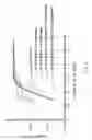
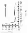
FIG. 2 illustrates LSV (linear sweep voltammetry) curves according to one embodiment of the present invention;
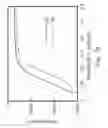
FIG. 3A illustrates first and second scans of LSV curves according to one embodiment of the present invention;
FIG. 3B illustrates the corresponding EQCM (electrochemical quartz crystal microbalance) responses of the first and second scans of LSV in FIG. 3A according to one embodiment of the present invention;
FIG. 3C illustrates an enlarged view of FIG. 3B;
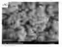
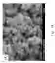
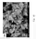
FIGS. 4A and 4B illustrate SEM (Scanning Electron Microscope) images according to one embodiment of the present invention;
FIGS. 4C and 4D illustrate TEM (Transmission Electron Microscope) images according to one embodiment of the present invention; and
FIGS. 4E and 4F illustrate depth profiles of XPS (X-ray photoelectron spectra) according to one embodiment of the present invention.
DESCRIPTION OF THE PREFERRED EMBODIMENT
FIG. 1 illustrates a flowchart of a titanium dioxide coating method including following steps. Beginning at step S1, an electrolyte containing Ti3+ and at least one of NO3− and NO2− initiates the redox reaction between Ti3+ and NO3−/NO2− to form Ti(IV) and NO2−/N2. This electrolyte is provided for an electrodeposition device. Next, at step S2, a substrate is then immersed into the electrolyte and at step S3, the substrate is electrically connected to the electrodeposition device. At step S4, a cathodic current is applied on the substrate via the electrodeposition device for reducing NO2− or NO3− to generate extensive OH− for depositing TiO2 films on the surface of substrates. The cathodic current can be applied by galvanostatic (constant dc current), potentiostatic (constant voltage), potentiodynamic, or galvanodynamic methods, or in the pulse voltage or pulse current modes.
The continuous reduction of NO2− to N2 and NH3 generates extensive OH−, and effectively enhances the deposition of TiO2 films on the surface of substrates.
In one embodiment, a post annealing step is further performed after forming the titanium dioxide film on the surface of the substrate, wherein the post annealing step is carried out at about 100-800° C.
The following descriptions of specific embodiments of the present invention have been presented for purposes of illustrations and description, and they are not intended to be exclusive or to limit the present invention to the precise forms disclosed, and obviously many modifications and variations are possible in light of the above teaching. It is intended that the scope of the invention can be defined by the Claims appended hereto and their equivalents.
TiO2 particulates are cathodically deposited onto graphite substrates from an electrolyte bath containing 0.47 M HCl, 25 mM TiCl3 and 75 mM NaNO3 in an electrodeposition device according to an embodiment of the present invention. A pretreatment procedure of graphite substrates may be performed and the detailed description thereof is herein omitted.
According to one embodiment of the present invention, the redox reaction between Ti3+ and NO3− during preparation of the deposition solution is herein disclosed. Nitrates, acting as the oxidizers, were reduced to NO2 (reddish-brown bubbles) when the transparent NaNO3 solution was added into the purple TiCl3 solution. Since NO2 molecules are soluble in aqueous media, they will automatically convert into NO3− and NO2−. This statement is supported by the observation that reddish-brown bubbles gradually disappear within 30-40 seconds and the purple TiCl3 solution in presence of Ti3+ is a colorless transparent solution indicating the formation of TiO2+ (see equations 1 and 2)
Ti3++NO3—→TiO2++NO2 (1)
2NO2+H2O→HNO3+HNO2 (2)
Curves 1-5 in FIG. 2 correspond to the i-E responses measured from various electrolytes. As can be seen from the curves 1 and 2, reduction commences at potentials negative to −0.6 V and no gas evolution is found at potentials positive to −0.6 V. However, a rapid generation of many bubbles is clearly observed when potentials are negative to −0.6 V, indicating H2 evolution. On curves 3 and 4, reduction starts in the more positive potential region, revealing the facile reduction of NaNO2. In addition, minor gas evolution commences from 0.4 V to −0.4 V with a low current density, while gas evolution ceases in the potential range from −0.4 V to −1.2 V and occurs dramatically again at potentials behind −1.2 V. The above results indicate that NO2− is responsible for the reduction in the more positive potential region with minor gas evolution, presumably due to the reduction of NO2− into N2 molecules. Since gas evolution temporarily disappears in the potential range from −0.4 V to −1.2 V. This result suggests a further reduction of N2 to NH4+ in such a negative potential range (see equations 3 and 4).
2NO2−+4H2O+6e→N2+8OH− (3)
N2+8H2O+6e→2NH4++8OH− (4)
On curve 5, gas evolves gently at about −0.1 V, disappears at ca. −0.4 V and, dramatically evolves again at potentials negative to −1.2 V, which completely follows the gas evolution-disappearance phenomena measured from the solution containing NO2−. Accordingly, NO2− reduction in the designed deposition bath for generating concentrated OH− at the vicinity of electrode surface is concluded to be an effective step in promoting the deposition of TiO(OH)2 (see equation 5). The TiO(OH)2 is then dehyrated to form TiO2.
TiO2++2OH−+xH2O→TiO(OH)2.xH2O (5)
The mechanism proposed in this invention not only reasonably interprets the gas evolution/disappearance phenomena but also explains the slight increase in bath pH after the deposition, which is different from the slight decrease in pH found in previous case of NO3− reduction. Based on equations 3 and 4, OH− is mainly provided by the NO2− reduction and the consequent N2 reduction, resulting in the generation of NH4+. As a result, a slight increase in pH found in this formulated solution after TiO2 deposition is reasonable because the OH−/electron ratio for the reduction of NO2− and N2 is 4/3, larger than the proton/electron ratio (equal to 1) for oxygen evolution at the anode. Moreover, the deposition rate in this formulated solution is very fast, attributable to the massive generation of OH−.
FIG. 3A illustrates the first and second scans of LSV (linear sweep voltammetry) curves and FIG. 3B illustrates the corresponding EQCM (electrochemical quartz crystal microbalance) responses of the first and second scans of LSV measured from the designed solution in order to precisely obtain the onset potential of deposition. A comparison of the i-E and mass-E responses indicates that there is always an incubation period for N2 evolution in the positive potential range, e.g., from 0.2 to −0.7 V and from 0.1 to −0.65 V for the first and second sweeps, respectively. Although in the incubation range, NO2− starts to be reduced to N2, no significant increase in mass is observed. The slight weight gain in this potential region is probably due to the NO2− adsorption at the cathode. Based on the EQCM result, once the potential is negative enough to generate/accumulate concentrated OH−, TiO2+ will combine with OH− to form TiO2 and an obvious weight gain is visible behind this onset potential of deposition (−0.85 and −0.65 V for the first and second scans, respectively). Also note the positive shift in the onset potential of deposition during the second scan. This phenomenon is probably due to the electrocatalytic property of TiO(OH)2 and TiO2 already deposited onto the graphite surface during the first scan for NO2−/N2 reduction.
The electrodes were cleaned in an ultrasonic DI water bath and dried under a cool air flow after cathodic deposition. After cleaning and drying, some electrodes were annealed at 400° C. in air for 1 hr. The morphologies were examined by a FE-SEM (Field-Emission Scanning Electron Microscope, FE-SEM). The EQCM study was performed by an electrochemical analyzer, CHI 4051A in a one-compartment cell. The microstructure and SAED (selected area electron diffraction, SAED) patterns of as-deposited and annealed TiO2 deposits were observed through a TEM (FEI E.O Tecnai F20 G2). The depth profiles of Ti and O were measured by an X-ray photoelectron spectrometer (XPS, ULVAC-PHI Quantera SXM), employed Al monochromator (hv=1486.69 eV) irradiation as the photosource.
It is favorable to prepare porous A-TiO2 films by combining cathodic deposition from this designed Ti3++NO3− solution and post-deposition annealing. As illustrated in FIGS. 4A and 4B, TiO2 films before and after annealing are porous and the particle size is roughly estimated to be 60-100 nm. The porous nature of TiO2 films prepared in this invention is probably due to the extensive tiny bubble evolution during the deposition. The particulates are considered as aggregates of TiO2 primary particles.
The average size for as-deposited TiO2 primary particles is about 6 nm, which is enlarged by post-deposition annealing (ca. 10 nm for TiO2 annealed at 400° C.) from FIGS. 4C and 4D. The lattice clearly visible in FIG. 4D and the diffraction rings in its inset indicate the anatase structure which is transformed from the amorphous, as-deposited TiO2 by post-deposition annealing. FIGS. 4E and 4F illustrate the depth profiles of Ti, O, and C for as-deposited and annealed samples. Clearly, the atomic ratio of Ti/O is approximately constant (ca. ½) within the whole oxide matrix.
This result confirms the formation of TiO2 in the as-prepared and annealed films. Accordingly, combining cathodic deposition from this designed Ti3+ +NO3− solution and post-deposition annealing is favorable for preparation of porous A-TiO2 films.
The aforementioned embodiment exemplified the reaction from the electrolyte solution containing Ti3++NO3−; however, the redox reaction between Ti3+ and NO2− in an electrolyte solution can be used for depositing titanium dioxide films (See Equation 6 and Equation 3-5).
6Ti3++2NO2-+2H2O→6TiO2++N2+4H+ (6)
To sum up, a titanium dioxide coating method according to the present invention includes a cathodic deposition using an electrolytic solution containing Ti3+ and at least one of NO3− and NO2−, and a post-deposition annealing process, which is favorable for preparing porous A-TiO2 films. The redox reaction between Ti3+ and NO3−/NO2− to form Ti(IV) and NO2−/N2 prior to cathodic deposition effectively promotes the TiO2 deposition. The continuous reduction of NO2− to N2 and NH3 generates extensive OH− and effectively enhances the deposition of TiO2 for forming a TiO2 film at the substrate surface.
The porous, anatase structure of annealed TiO2, examined by FE-SEM, TEM, and SAED analyses is expected to be good for the dye-sensitized solar cell (DSSC) application. In addition, A-TiO2 may be applicable for water and air purifications, photocatalysts, gas sensors, electrochromic devices, and so on.
While the invention is susceptible to various modifications and alternative forms, a specific example thereof has been shown in the drawings and is herein described in detail. It should be understood, however, that the invention is not to be limited to the particular form disclosed, but to the contrary, the invention is to cover all modifications, equivalents, and alternatives falling within the spirit and scope of the appended claims.
Claims
What is claimed is:1. A titanium dioxide coating method comprising:
providing an electrolyte containing Ti3+ and at least one of NO3− and NO2− for an electrodeposition device;
immersing a substrate into the electrolyte;
electrically connecting the substrate to the electrodeposition device; and
applying a cathodic current to the substrate via the electrodeposition device for reducing NO2− or NO3− to generate extensive OH− for forming a titanium dioxide film on the surface of the substrate.
2. The method as claimed in claim 1 further comprising a post annealing step after forming the titanium dioxide film.
3. The method as claimed in claim 2, wherein the post annealing step is carried out at about 100-800° C.
4. The method as claimed in claim 1, wherein the cathodic current is applied by galvanostatic (constant dc current), potentiostatic (constant voltage), potentiodynamic, or galvanodynamic methods, or in the pulse voltage or pulse current modes.
5. The method as claimed in claim 1, wherein NO2− and TiO2+ are generated by a reaction between Ti3+ and NO3−, and NO2− is generated by the reaction between NO2 and water.
6. The method as claimed in claim 5, wherein OH− is generated by reduction of NO2− at the cathode.
7. The method as claimed in claim 6, wherein TiO(OH)2 is generated from a reaction between TiO2+ and OH− and then dehydrated to form TiO2.
8. The method as claimed in claim 7, wherein the generation of OH− by the NO2− reduction at the cathode is catalyzed by TiO(OH)2 and TiO2.
9. The method as claimed in claim 1, wherein TiO2+ and N2 are generated from the reaction between Ti3+ and NO2−.
10. The method as claimed in claim 9, wherein OH− is generated by reduction of NO2−/N2 at the cathode.
11. The method as claimed in claim 10, wherein TiO(OH)2 is generated from a reaction between TiO2+ and OH− and then dehydrated to form TiO2.
12. The method as claimed in claim 11, wherein the generation of OH− by the NO2−/N2 reduction at the cathode is catalyzed by TiO(OH)2 and TiO2.
13. The method as claimed in claim 1, wherein the electrolyte is acidic.
14. A titanium dioxide film is obtained by the method as claimed in claim 1.
15. The titanium dioxide film as claimed in claim 14 is crystalline.
16. The titanium dioxide film as claimed in claim 14 is amorphous.
17. The titanium dioxide film as claimed in claim 14 is porous.
18. An electrolyte for titanium dioxide coating comprising:
Ti3+ and at least one of NO3− and NO2−.
19. The electrolyte as claimed in claim 18 is acidic.
Images & Drawings included:


Sources:
- United States Patent and Trademark Office - verify current appl. status at the USPTO↗
Recent applications in this class:
- » 20250059059 2025-02-20
COMPOSITE PARTICLE PRODUCTION METHOD AND COMPOSITE PARTICLE - » 20250033988 2025-01-30
SYNTHESIS, CAPPING AND DISPERSION OF HIGH REFRACTIVE INDEX NANOCRYSTALS AND NANOCOMPOSITES - » 20240076198 2024-03-07
SUB-100 NM OXIDIZED TRANSITION METAL TUBULAR ARCHITECTURES - » 20230399236 2023-12-14
TITANIUM DIOXIDE NANOMATERIALS AND METHOD OF MAKING THE SAME - » 20230109156 2023-04-06
PARTICLE, POWDER COMPOSITION, SOLID COMPOSITION, LIQUID COMPOSITION, AND COMPACT - » 20210292183 2021-09-23
Sub-100 nm oxidized transition metal tubular architectures - » 20210061669 2021-03-04
TITANIUM OXIDE POWDER, AND DISPERSION LIQUID AND COSMETIC USING SAID POWDER - » 20200325034 2020-10-15
Titanium oxide powder, and dispersion and cosmetic using said powder - » 20200325033 2020-10-15
Hydrophobic and oleophobic nanocomposite material, method for making same, and encapsulating structure utilizing same - » 20200290888 2020-09-17
Photocatalytic Roofing Granules, Photocatalytic Roofing Products, and Process for Preparing Same