LED lamp
US20100296300A1
2010-11-25
12/453,707
2009-05-20
Abstract:
An LED lamp includes a glass electric light bulb (1) including a rear hollow projection (2) open to a rear end, the projection (2) having outer threads (6); a socket (4) including front inner threads (7) and two conductors (9) having rear ends connected to a pair of electric wires (8); a conductive mounting member (3) fastened in a front portion of the socket (4) and electrically connected to the conductors (9); and an LED (5) having two legs (51) inserted into the conductive mounting member (3) to fasten them together wherein the fastened LED (5) is electrically connected to the conductive mounting member (3). The bulb (1) is secured to the socket (4) by threadedly securing the outer threads (6) to the inner threads (7).
Interested in similar patents?
Get notified when new applications in this technology area are published.
Classification:
F21V17/12 » CPC main
Fastening of component parts of lighting devices, e.g. shades, globes, refractors, reflectors, filters, screens, grids or protective cages characterised by specific fastening means or way of fastening by screwing
F21S6/001 » CPC further
Lighting devices intended to be free-standing being candle-shaped
F21V3/02 » CPC further
Globes; Bowls; Cover glasses characterised by the shape
F21Y2115/10 » CPC further
Light-generating elements of semiconductor light sources Light-emitting diodes [LED]
F21S13/10 IPC
Non-electric lighting devices or systems employing a point-like light source; Non-electric lighting devices or systems employing a light source of unspecified shape; Devices intended to be fixed, e.g. ceiling lamp, wall lamp with a standard, e.g. street lamp
Description
BACKGROUND OF THE INVENTION
1. Field of Invention
The invention relates to electric light bulbs and more particularly to an LED (light-emitting diode) lamp with improved characteristics including reduced assembly time and increased reliability in use.
2. Description of Related Art
LEDs are renowned for their long life and their ability to resist shock. Also, an LED consumes much less electrical power than fluorescent lamps (i.e., energy saving). Therefore, LED lighting devices are gaining popularity worldwide.
There have been numerous suggestions in prior patents for LED lamp. For example, U.S. Pat. No. 5,414,605 discloses a lamp assembly, U.S. Pat. No. 5,499,174 discloses a decorative lamp assembly, and U.S. Pat. No. 5,517,394 discloses a decorative lamp assembly. However, the structure of each of above patents is complicated. Further, the prior lamps are expensive to manufacture, trouble-prone, and unreliable in use.
In addition, U.S. Pat. No. 7,086,767 discloses a thermally efficient LED bulb. Thus, continuing improvements in the exploitation of LED lamp are constantly being sought.
SUMMARY OF THE INVENTION
It is therefore one object of the invention to provide an LED lamp having the advantages of reduced assembly time and increased reliability in use.
To achieve the above and other objects, the invention provides an LED lamp comprising an electric light bulb formed of glass, the bulb including a rear hollow projection open to a rear end, the projection having outer threads; a socket including front inner threads and two conductors having rear ends connected to a pair of electric wires; a conductive mounting member fastened in a front portion of the socket and electrically connected to the conductors; and an LED having two legs inserted into the conductive mounting member to fasten them together wherein the fastened LED is electrically connected to the conductive mounting member, wherein the bulb is secured to the socket by threadedly securing the outer threads to the inner threads.
The above and other objects, features and advantages of the invention will become apparent from the following detailed description taken with the accompanying drawings.
BRIEF DESCRIPTION OF THE DRAWINGS
FIG. 1 is a longitudinal sectional view of bulb of an LED lamp according to the invention;
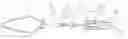
FIG. 2 is a longitudinal sectional view of the components of the LED lamp to be assembled;
FIG. 3 is a longitudinal sectional view of the assembled LED lamp; and
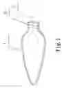
FIG. 4 is a longitudinal sectional view of an LED lamp mounted with a spherical bulb different from the bulbous one shown in FIGS. 1 to 3.
DETAILED DESCRIPTION OF THE INVENTION
Referring to FIGS. 1 to 3, an LED lamp in accordance with the invention comprises the following components as discussed in detail below.
A bulbous electric light bulb 1 is made of glass. The bulb 1 has a hollow projection 2 open to a rear. Threads 6 are formed on an outer surface of the projection 2. A socket 4 has inner threads 7 formed on its front portion. A pair of electric wires 8 is extended out of a rear end of the socket 4. A conductive mounting member 3 is fastened in the front portion of the socket 4 by snapping. The fastened conductive mounting member 3 is electrically connected to the electric wires 8 via two conductors 9. An LED 5 has two extending legs 51 adapted to insert into the conductive mounting member 3 to secure them together by snapping. The fastened LED 5 is also electrically connected to the conductive mounting member 3. The bulb 1 is secured to the socket 4 by threadedly securing the outer threads 6 to the inner threads 7. This also completes the assembly of the LED lamp. It is envisaged by the invention that benefits such as reduced assembly time and increased reliability in use can be obtained.
Referring to FIG. 4, the bulbous bulb 1 in FIGS. 1 to 3 is replaced with a spherical bulb 1.
While the invention herein disclosed has been described by means of specific embodiments, numerous modifications and variations could be made thereto by those skilled in the art without departing from the scope and spirit of the invention set forth in the claims.
Claims
What is claimed is:1. An LED lamp comprising:
an electric light bulb (1) formed of glass, the bulb (1) including a rear hollow projection (2) open to a rear end, the projection (2) having outer threads (6);
a socket (4) including front inner threads (7) and two conductors (9) having rear ends connected to a pair of electric wires (8);
a conductive mounting member (3) fastened in a front portion of the socket (4) and electrically connected to the conductors (9); and
an LED (5) having two legs (51) inserted into the conductive mounting member (3) to fasten them together wherein the fastened LED (5) is electrically connected to the conductive mounting member (3),
wherein the bulb (1) is secured to the socket (4) by threadedly securing the outer threads (6) to the inner threads (7).
Images & Drawings included:


Sources:
- United States Patent and Trademark Office - verify current appl. status at the USPTO↗
Similar patent applications:
- » 20120113631
Base for LED lamp, base set for LED lamp, socket set for LED lamp, and lamp assembly using the same - » 20140117853
LED lamp, illumination device including the LED lamp and current control method of the LED lamp - » 20220183121
Driving circuit for LED lamp, LED lamp containing same and method for operating driving circuit - » 20180288842
Lamp driver for an LED lamp and LED lamp for placement into a fluorescent lamp fixture - » 20180160564
Method and system for controlling fan rotating speed of LED lamp, and LED lamp thereof - » 20120019166
Power source unit for LED lamps, and LED lamp system - » 20060109661
LED lamp with LEDs on a heat conductive post and method of making the LED lamp - » 20110115391
LED LAMP AND LED LAMP MODULE - » 20060261362
LED lamp and LED lamp apparatus - » 20170051911
WATERPROOF LED LAMP AND LED LAMP SET
Recent applications in this class:
- » 20250137620 2025-05-01
CONDUIT LIGHT FIXTURE - » 20240255124 2024-08-01
THREADED INSERT FOR AN AIRFIELD LIGHT FIXTURE - » 20220235920 2022-07-28
Modular outdoor light fixture and accessories - » 20220235919 2022-07-28
TEMPORARY-TO-PERMANENT LIGHTING SYSTEM - » 20220042674 2022-02-10
Luminaire system with improved fastening means - » 20210356100 2021-11-18
Ground Insert lamp Installed Quickly - » 20210140610 2021-05-13
Apparatus to detachably attach LED light fixture to ceiling or recessed lighting fixture housing - » 20210071849 2021-03-11
Waterproof stage lamp structure easy to disassemble and maintain and waterproof stage lamp - » 20200393113 2020-12-17
Intelligent induction miner's lamp - » 20200340645 2020-10-29
Lighting apparatus