Phosphor-containing LED light bulb
US20100301727A1
2010-12-02
12/678,287
2008-09-12
✅ Patent granted
US 8,450,927 B2
2013-05-28
WO; PCT/US2008/010713; 20080912
WO; WO2009/035693; 20090319
Joseph L Williams
Morrison & Foerster LLP
2029-03-04
Abstract:
An LED bulb, which includes a shell, a filler material within the shell of the bulb, at least one type of phosphor dispersed inside the filler material and at least one LED within the shell.
Inventors:
- Ronald J. LENK 29 🇺🇸 Woodstock, GA, United States
- Bruce CARSTEN 5 🇺🇸 Corvallis, OR, United States
Assignee:
- Switch Bulb Company, Inc. 67 🇺🇸 San Jose, CA, United States
- SUPERBULBS, INC. 8 🇺🇸 Redwood City, CA, United States
Applicant:
Interested in similar patents?
Get notified when new applications in this technology area are published.
Classification:
F21V29/56 » CPC main
Protecting lighting devices from thermal damage; Cooling or heating arrangements specially adapted for lighting devices or systems; Cooling arrangements using liquid coolants
F21K9/232 » CPC further
Light sources using semiconductor devices as light-generating elements, e.g. using light-emitting diodes [LED] or lasers; Light sources comprising attachment means; Retrofit light sources for lighting devices with a single fitting for each light source, e.g. for substitution of incandescent lamps with bayonet or threaded fittings specially adapted for generating an essentially omnidirectional light distribution, e.g. with a glass bulb
F21K9/64 » CPC further
Light sources using semiconductor devices as light-generating elements, e.g. using light-emitting diodes [LED] or lasers; Optical arrangements integrated in the light source, e.g. for improving the colour rendering index or the light extraction using wavelength conversion means distinct or spaced from the light-generating element, e.g. a remote phosphor layer
F21V3/00 » CPC further
Globes; Bowls; Cover glasses
H05B33/145 » CPC further
Electroluminescent light sources; Light sources with substantially two-dimensional radiating surfaces characterised by the chemical or physical composition or the arrangement of the electroluminescent material, or by the simultaneous addition of the electroluminescent material in or onto the light source Arrangements of the electroluminescent material
F21Y2115/10 » CPC further
Light-generating elements of semiconductor light sources Light-emitting diodes [LED]
H01L33/507 » CPC further
Semiconductor devices with at least one potential-jump barrier or surface barrier specially adapted for light emission; Processes or apparatus specially adapted for the manufacture or treatment thereof or of parts thereof; Details thereof characterised by the semiconductor body packages; Wavelength conversion elements the elements being in intimate contact with parts other than the semiconductor body or integrated with parts other than the semiconductor body
H01J1/62 IPC
Details of electrodes, of magnetic control means, of screens, or of the mounting or spacing thereof, common to two or more basic types of discharge tubes or lamps; Screens on or from which an image or pattern is formed, picked-up, converted, or stored; Luminescent coatings on vessels Luminescent screens; Selection of materials for luminescent coatings on vessels
H01J7/24 IPC
Details not provided for in the preceding groups and common to two or more basic types of discharge tubes or lamps Cooling arrangements; Heating arrangements; Means for circulating gas or vapour within the discharge space
H05B33/00 IPC
Electroluminescent light sources
H01J61/42 IPC
Gas-discharge or vapour-discharge lamps; Details; Devices for influencing the colour or wavelength of the light by transforming the wavelength of the light by luminescence
Description
FIELD OF THE INVENTION
The present invention relates to replacement of bulbs used for lighting by light emitting diode (LED) bulbs, and more particularly, to the dispersal of the phosphor used by the LEDs into the bulb in order to permit greater amounts of phosphor to be used, to permit cooler operating temperature of the phosphor, and to permit the LEDs to be run at higher power.
BACKGROUND OF THE INVENTION
An LED consists of a semiconductor junction, which emits light due to a current flowing through the junction. A white LED is typically made by using a blue or ultraviolet LED die, and adding a plastic coat to it, the coat containing a phosphor. The phosphor is used to convert the blue or ultraviolet light emitted by the LED die to a spectrum of light that more or less closely resembles white light or blackbody radiation.
At first sight, it would seem that white LEDs should make an excellent replacement for the traditional tungsten filament incandescent bulb. At equal power, they give far more light output than do incandescent bulbs, or, what is the same thing, they use much less power for equal light; and their operational life is orders of magnitude larger, namely, 10-100 thousand hours vs. 1-2 thousand hours.
However, LEDs have a number of drawbacks that have prevented them, so far, from being widely adopted as incandescent replacements. One of these is that, although LEDs require substantially less power for a given light output than do incandescent bulbs, it still takes many watts to generate adequate light for illumination. Whereas the tungsten filament in an incandescent bulb operates at a temperature of approximately 3000K, an LED cannot be allowed to get hotter than approximately 120° C., and some are limited to even lower maximum temperatures. The LED thus has a substantial heat problem: If operated in vacuum like an incandescent, or even in air, the LED would rapidly get too hot and fail. This has limited available LED bulbs to very low power (less than approximately 3 W), producing insufficient illumination for incandescent replacements.
One of the reasons that an LED is limited to such a low maximum temperature is due to the temperature characteristics of the phosphor rather than the LED die itself. Presently known phosphors, especially those in the red, tend to degrade quite rapidly at elevated temperatures. Once degradation has occurred, the white light output of the LED is reduced, thus ending the useful life of the LED and of the LED bulb.
SUMMARY OF THE INVENTION
This invention has the object of developing a light emitting apparatus utilizing light emitting diodes (LEDs), such that the above-described primary problem is effectively solved. In accordance with one embodiment, a replacement bulb for incandescent lighting having a plurality of LEDs with a light output equal in intensity to that of an incandescent bulb, and wherein the LEDs' temperature may be permitted to rise much higher than the present state-of-the-art permits. The apparatus includes a bulb-shaped shell, preferentially formed of a plastic such as polycarbonate. The shell may be transparent, or may contain materials dispersed in it to disperse the light, making it appear not to have point sources of light.
The shell is filled with a filler material, which can be a fluid, a gel, a plastic or other material, such as water or a hydrogel, which is preferentially thermally conductive. The filler material acts as a means to transfer the heat power generated by the LEDs to the shell, where it may be removed by radiation and convection, as in a normal incandescent bulb. In accordance with a preferred embodiment, the filler material contains phosphor dispersed throughout the material, which changes the bluish color of the LED dice's light to a more yellowish color, more closely resembling the light from normal incandescent bulbs. It can be appreciated that in accordance with another embodiment, the filler material and phosphor material therein may also be used for changing the color emitted by other LED dice. In accordance with a preferred embodiment, the filler is preferentially electrically insulating.
In accordance with one embodiment, the phosphor may be uniformly distributed throughout the filler material. The phosphor density may be set to be higher or lower than that commonly used in LEDs today, a higher density producing more total conversion of the LED dice's light.
In accordance with another embodiment, the phosphor may be distributed in the filler material with an orientation preference, wherein the orientation preference can be used to generate light that is more intense in converted light in one direction than another.
In accordance with another embodiment, different phosphors may be distributed in the filler material with an orientation preference, wherein the orientation preference can be used to generate light that is different colors in one direction than another.
According to the present invention, a phosphor is distributed in a filler inside an LED light bulb for the purpose of changing the color of the light emitted by the LED into a more desirable color for emission from the bulb. Such a color-changing application is described in detail and set forth in Stokes et al., U.S. Pat. No. 6,791,259 (hereinafter “the '259”), which is incorporated herein by reference in its entirety with regard to all aspects thereof. As set forth in the '259 patent, a radiation-scattering material is located between the LEDs and the phosphor.
Such a filler is described in detail and set forth in Diamantidis, U.S. Publication No. 20070090391 (hereinafter “the '391 publication”), which is incorporated herein by reference in its entirety. As set forth in the '391 publication, a liquid fluid is in contact with the light-emitting chip crystal.
BRIEF DESCRIPTION OF THE DRAWINGS
The accompanying drawings are included to provide a further understanding of the invention, and are incorporated in and constitute a part of this specification. The drawings illustrate embodiments of the invention and, together with the description, serve to explain the principles of the invention.
FIG. 1 is a cross-sectional view of a present state-of-the-art LED showing its construction with phosphor in its shell.
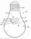
FIG. 2 is a cross-sectional view of an LED bulb showing the LED mounted in a filler material containing phosphor.
FIG. 3 is a cross-sectional view of an LED bulb showing an LED without phosphor mounted in a filler material containing phosphor.
FIG. 4 is a cross-sectional view of an LED bulb showing the LED mounted in a filler material containing phosphor with an orientation preference.
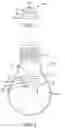
FIG. 5 is a cross-sectional view of an LED bulb showing the LED mounted in a filler material containing multiple phosphors with an orientation and location preference.
DESCRIPTION OF THE PREFERRED EMBODIMENTS
Reference will now be made in detail to the present preferred embodiments of the invention, examples of which are illustrated in the accompanying drawings. Wherever possible, the same reference numbers are used in the drawings and the description to refer to the same or like parts.
According to the design characteristics, a detailed description of the current practice and preferred embodiments is given below.
FIG. 1 is a cross-sectional view of a present state-of-the-art LED 10 showing its construction with phosphor in its shell. As shown in FIG. 1, the LED includes an LED die 30, a base 20 to which the LED die 30 is mounted for electrical and thermal connection, and a shell 40. The shell 40 is used to protect the LED die 30 from the air, forms optics for the LED die 30, and contains phosphor 50 to convert the light spectrum emitted by the LED die 30 to a more desirable spectrum.
FIG. 2 is a cross-sectional view of an LED bulb 60 showing the LED 10 mounted in a filler material containing phosphor. As shown in FIG. 2, the LED includes an LED die 30, a base 20 to which the LED die 30 is mounted, and a shell 40. The shell 40 is used to protect the LED die 30 from the filler material, provides optics for the LED die 30, and contains one or more phosphors 50. The shell 70 of the LED bulb 60 contains both the LED 10 and a filler material 100. The filler material contains dispersed in it phosphor 90, to convert the light spectrum emitted by the LED 10 to a more desirable spectrum. Also shown is a screw base 80, which makes contact with an electrical socket, and converts power from the electrical socket to power suitable for powering the LED.
FIG. 3 is a cross-sectional view of an LED bulb 60 showing an LED 10 mounted in a filler material containing phosphor. As shown in FIG. 3, the LED includes an LED die 30, a base 20, and a shell 40. The shell 40 is used to protect the LED die 30 from the filler material, and may form optics, but contains no phosphor. The shell 70 of the LED bulb 60 contains both the LED 10 and a filler material 100. Said filler material contains dispersed in it one or more phosphors 90, to convert the light spectrum emitted by the LED 10 to a more desirable spectrum. Also shown is a screw base 80, which makes contact with an electrical socket, and converts power from the electrical socket to power suitable for powering the LED.
FIG. 4 is a cross-sectional view of an LED bulb 60 showing the LED 10 mounted in a filler material containing phosphor with an orientation preference. As shown in FIG. 4, the LED includes an LED die 30, a base 20, and a shell 40. The shell 40 is used to protect the LED die 30 from the filler material, but contains no phosphor. The shell 70 of the LED bulb 60 contains both the LED 10 and a filler material 100. Said filler material contains dispersed in it a single phosphor 110 and 120, to convert the light spectrum emitted by the LED 10 to a more desirable spectrum. Said phosphor is not uniformly distributed in the filler material 100, but rather has a preferred orientation. Shown as an example, a portion of the phosphor 110 is concentrated towards the middle of the bulb 60, whereas another portion of the phosphor 120 is distributed throughout the rest of said bulb. Also shown is a screw base 80, which makes contact with an electrical socket, and converts power from the electrical socket to power suitable for powering the LED.
FIG. 5 is a cross-sectional view of an LED bulb 60 showing the LED 10 mounted in a filler material containing multiple phosphors with an orientation and location preference. As shown in FIG. 5, the LED includes an LED die 30, a base 20, and a shell 40. The shell 40 is used to protect the LED die 30 from the filler material, but contains no phosphor. The shell 70 of the LED bulb 60 contains both the LED 10 and a filler material 100. The filler material contains in this example dispersed in it two different phosphors 110, 130 (i.e., a first and a second phosphor 111, 130), to convert the light spectrum emitted by the LED 10 to more desirable spectra. In accordance with one embodiment, the phosphors 110, 130 are not uniformly distributed in the filler material 100, but rather have a preferred orientation and location. As shown, a first phosphor 110 is preferentially distributed towards the middle of the bulb 60, whereas a second phosphor 130 is preferentially distributed towards the outside of the bulb. Also shown is a screw base 80, which makes contact with an electrical socket, and converts power from the electrical socket to power suitable for powering the LED.
It will be apparent to those skilled in the art that various modifications and variation can be made to the structure of the present invention without departing from the scope or spirit of the invention. In view of the foregoing, it is intended that the present invention cover modifications and variations of this invention provided they fall within the scope of the following claims and their equivalents.
Claims
What is claimed is:1. An LED bulb comprising:
a shell;
a filler material within the shell of the bulb;
at least one type of phosphor dispersed inside the filler material; and
at least one LED within the shell.
2. An LED bulb as set forth in claim 1, wherein the filler material is a fluid.
3. An LED bulb as set forth in claim 1, wherein the filler material is a gel.
4. An LED bulb as set forth in claim 1, wherein the filler material is a plastic.
5. An LED bulb as set forth in claim 1, wherein the filler material is glass.
6. An LED bulb as set forth in claim 1, wherein the filler material is thermally conductive.
7. An LED bulb as set forth in claim 1, wherein the at least one phosphor is uniformly distributed throughout the filler material.
8. An LED bulb as set forth in claim 1, wherein the at least one phosphor has a non-uniform distribution throughout the filler material.
9. An LED bulb as set forth in claim 1, wherein the at least one phosphor is comprised of at least two phosphors, and wherein the at least two phosphors comprises at least one phosphor having a different distribution from the others throughout the filler material.
10. An LED bulb as set forth in claim 1, wherein the shell contains at least one phosphor.
11. An LED bulb as set forth in claim 1, wherein the at least one LED is a blue or ultraviolet LED without a phosphor.
12. An LED bulb as set forth in claim 1, wherein the at least one LED is a blue or ultraviolet LED die.
13. An LED incandescent bulb replacement comprising:
an incandescent bulb-shaped shell;
a filler material within the shell of the bulb;
at least one type of phosphor dispersed inside the filler material; and
at least one LED within the shell.
14. An LED bulb as set forth in claim 13, wherein the filler material is a fluid.
15. An LED bulb as set forth in claim 13, wherein the filler material is a gel.
16. An LED bulb as set forth in claim 13, wherein the filler material is a plastic.
17. An LED bulb as set forth in claim 13, wherein the filler material is glass.
18. An LED bulb as set forth in claim 13, wherein the filler material is thermally conductive.
19. An LED bulb as set forth in claim 13, wherein the at least one phosphor is uniformly distributed throughout the filler material.
20. An LED bulb as set forth in claim 13, wherein the at least one phosphor has a non-uniform distribution throughout the filler material.
21. An LED bulb as set forth in claim 13, wherein the at least one phosphor is comprised of at least two phosphors, with at least one phosphor having a different distribution from the other phosphors throughout the filler material.
22. An LED bulb as set forth in claim 13, wherein the shell contains at least one phosphor.
23. An LED bulb as set forth in claim 13, wherein the at least one LED is a blue or ultraviolet LED without a phosphor.
24. An LED bulb as set forth in claim 13, wherein the at least one LED is a blue or ultraviolet LED die.
25. An LED bulb as set forth in claim 13, wherein the filler material is a hydrogel.
26. An LED bulb as set forth in claim 25, wherein the hydrogel contains at least one phosphor uniformly distributed throughout the said hydrogel.
27. An LED bulb as set forth in claim 25, wherein the hydrogel contains at least one phosphor having a non-uniform distribution throughout the said hydrogel.
28. An LED bulb as set forth in claim 25, wherein said hydrogel contains at least two phosphors, with at least one phosphor having a different distribution from the other phosphors throughout the hydrogel.
Images & Drawings included:


Sources:
- United States Patent and Trademark Office - verify current appl. status at the USPTO↗
Similar patent applications:
- » 20130264933
Phosphor-containing LED light bulb - » 20140175973
Phosphor-containing LED light bulb
Recent applications in this class:
- » 20250277581 2025-09-04
LED LIGHT SOURCE DEVICE AND BIOCHEMICAL ANALYSIS DEVICE - » 20230007892 2023-01-12
LIGHT-EMITTING DEVICE - » 20220341580 2022-10-27
Systems and methods for a coolant chamber - » 20220090772 2022-03-24
WATER-COOLED GROW LIGHT APPARATUS - » 20220065433 2022-03-03
Light source unit and light irradiation device - » 20210156553 2021-05-27
Emitter including a LED element and method for emitting light by means of an emitter - » 20210063007 2021-03-04
Water-cooled grow light apparatus - » 20190137088 2019-05-09
Easily formed liquid cooling module of an LED lamp - » 20180283674 2018-10-04
LED lamp with heat dissipation effect - » 20180283673 2018-10-04
LED LIGHTING MODULE, SYSTEM, AND METHOD
Recent applications for this Assignee:
- » 20150260353 2015-09-17
LIQUID-FILLED LED BULB HAVING A UNIFORM LIGHT-DISTRIBUTION PROFILE - » 20150260352 2015-09-17
LED BULB WITH CHASSIS FOR PASSIVE CONVECTIVE LIQUID COOLING - » 20150184815 2015-07-02
LED bulb having an adjustable light-distribution profile - » 20150102724 2015-04-16
THERMAL PROTECTION CIRCUIT FOR AN LED BULB - » 20150078016 2015-03-19
ANTI-THEFT COLLAR FOR AN LED LIGHT BULB HAVING COOLING FINS - » 20150078015 2015-03-19
ANTI-THEFT COLLAR FOR A LIGHT BULB - » 20150023029 2015-01-22
OMNI-DIRECTIONAL CHANNELING OF LIQUIDS FOR PASSIVE CONVECTION IN LED BULBS - » 20140333193 2014-11-13
GLASS LED LIGHT BULBS - » 20140327369 2014-11-06
Three-level LED bulb microprocessor-based driver - » 20140265923 2014-09-18
LED bulb with color-shift dimming