High pressure discharge lamp
US20100301745A1
2010-12-02
12/679,033
2008-08-21
✅ Patent granted
US 8,115,390 B2
2012-02-14
WO; PCT/EP2008/060928; 20080821
WO; WO2009/037063; 20090326
Mariceli Santiago
2029-01-13
Abstract:
A high-pressure discharge lamp may include a ceramic discharge vessel and a longitudinal axis, with electrodes respectively being led out from the discharge vessel by means of a feed-through via capillaries, wherein a tubular cermet part, which consists of individual layers of different composition layered axially in succession, is fitted on the capillary, each layer containing Mo and Al2O3, the proportion of Mo in the first layer facing toward the capillary being from 3 to 15 vol. % and in the last layer being from 85 to 97 vol. %, and a molybdenum cover cap, the cover cap being welded to the feed-through and the cover cap being connected to the cermet part by means of solder containing metal, and the connection between the capillary and the cermet part being established by means of high-melting glass solder or sinter-active Al2O3 powder.
Inventors:
- Steffen Walter 37 🇩🇪 Oberpframmern, Germany
- Roland Huettinger 13 🇩🇪 Kaufering, Germany
- Khanh Pham Gia 8 🇩🇪 Neubiberg, Germany
- Stefan Juengst 4 🇩🇪 Zorneding, Germany
- Stefan Kotter 1 🇩🇪 Rotthalmuenster, Germany
- Stefan Kotter 1 🇩🇪 Rotthalmuenster 2, Germany
Assignee:
- OSRAM AG 172 🇩🇪 Münich, Germany
- OSRAM GESELLSCHAFT MIT BESCHRAENKTER HAFTUNG 235 🇩🇪 Muenchen, Germany
Interested in similar patents?
Get notified when new applications in this technology area are published.
Classification:
H01J61/366 » CPC main
Gas-discharge or vapour-discharge lamps; Details; Seals between parts of vessels; Seals for leading-in conductors; Leading-in conductors Seals for leading-in conductors
C04B35/117 » CPC further
Shaped ceramic products characterised by their composition ; Ceramics compositions ; Processing powders of inorganic compounds preparatory to the manufacturing of ceramic products based on oxide ceramics based on aluminium oxide; Fine ceramics Composites
C22C29/12 » CPC further
Alloys based on carbides, oxides, nitrides, borides, or silicides, e.g. cermets, or other metal compounds, e.g. oxynitrides, sulfides based on oxides
C22C32/0031 » CPC further
Non-ferrous alloys containing at least 5% by weight but less than 50% by weight of oxides, carbides, borides, nitrides, silicides or other metal compounds, e.g. oxynitrides, sulfides whether added as such or formed with only oxides with only single oxides as main non-metallic constituents Matrix based on refractory metals, W, Mo, Nb, Hf, Ta, Zr, Ti, V or alloys thereof
H01J9/323 » CPC further
Apparatus or processes specially adapted for the manufacture, installation, removal, maintenance of electric discharge tubes, discharge lamps, or parts thereof; Recovery of material from discharge tubes or lamps; Manufacture or joining of vessels, leading-in conductors or bases; Sealing leading-in conductors Sealing leading-in conductors into a discharge lamp or a gas-filled discharge device
C04B2235/404 » CPC further
Aspects relating to ceramic starting mixtures or sintered ceramic products; Composition of constituents of the starting material or of secondary phases of the final product; Constituents and secondary phases not being of a fibrous nature; Metallic constituents or additives not added as binding phase Refractory metals
B22F2998/10 » CPC further
Supplementary information concerning processes or compositions relating to powder metallurgy Processes characterised by the sequence of their steps
C22C1/051 » CPC further
Making alloys by powder metallurgy; Mixtures of metal powder with non-metallic powder Making hard metals based on borides, carbides, nitrides, oxides or silicides; Preparation of the powder mixture used as the starting material
B22F3/22 » CPC further
Manufacture of workpieces or articles from metallic powder characterised by the manner of compacting or sintering; Apparatus specially adapted therefor ; Presses and furnaces for producing castings from a slip
B22F5/006 » CPC further
Manufacture of workpieces or articles from metallic powder characterised by the special shape of the product of flat products, e.g. sheets
B22F7/06 » CPC further
Manufacture of composite layers, workpieces, or articles, comprising metallic powder, by sintering the powder, with or without compacting wherein at least one part is obtained by sintering or compression of composite workpieces or articles from parts, e.g. to form tipped tools
B22F2999/00 » CPC further
Aspects linked to processes or compositions used in powder metallurgy
B22F5/106 » CPC further
Manufacture of workpieces or articles from metallic powder characterised by the special shape of the product of articles with cavities or holes, not otherwise provided for in the preceding subgroups Tube or ring forms
B22F2207/03 » CPC further
Aspects of the compositions, gradients; Composition gradients of the metallic binder phase in cermets
C04B37/02 IPC
Joining burned ceramic articles with other burned ceramic articles or other articles by heating with metallic articles
H01J61/36 IPC
Gas-discharge or vapour-discharge lamps; Details Seals between parts of vessels; Seals for leading-in conductors; Leading-in conductors
H01J17/18 IPC
Gas-filled discharge tubes with solid cathode; Details Seals between parts of vessels; Seals for leading-in conductors; Leading-in conductors
H01J9/00 IPC
Apparatus or processes specially adapted for the manufacture, installation, removal, maintenance of electric discharge tubes, discharge lamps, or parts thereof; Recovery of material from discharge tubes or lamps
Description
TECHNICAL FIELD
The invention is based on a high-pressure discharge lamp according to the preamble of claim 1.
PRIOR ART
U.S. Pat. No. 5,861,714 and U.S. Pat. No. 5,742,123 disclose a high-pressure discharge lamp in which a ceramic discharge vessel uses an axially layered cermet part for sealing at its ends.
In U.S. Pat. No. 5,742,123, a tungsten rod having a screw thread is fitted into a cermet part, the individual layers of which increase outward in their thickness. A platinum solder covers a flange on the cermet part. The number of layers is about 10. The first layer is placed directly onto the end of the discharge vessel, and the last layer is hermetically connected to the flange and the tungsten rod by means of the platinum solder.
In U.S. Pat. No. 5,861,714, the sealing between the last layer and the feed-through is produced by direct sintering and optionally assistance by means of glass solder. In both cases, the cermet parts are difficult to produce. The lifetime is unsatisfactory owing to the small number of stages and owing to the concept of sealing the feed-through in the last layer.
SUMMARY OF THE INVENTION
It is an object of the present invention to provide a high-pressure discharge lamp having a ceramic discharge vessel, the sealing of which is based on the concept of an axial gradient cermet and for the first time offers a sufficient lifetime for use in general lighting.
This object is achieved by characterizing features of claim 1.
Particularly advantageous configurations may be found in the dependent claims.
The sealing technique in Hg high-pressure discharge lamps having a ceramic discharge vessel, particularly with an aggressive metal halide fill, still represents an unsatisfactorily resolved problem owing to the different thermal expansion coefficients of the individual components.
Above all in the region of the electrical connections, cracks are formed since the various thermal expansion coefficients when heating and re-cooling in the processes of switching on and off are so different from one another. The Al2O3 used for the discharge vessel has a typical thermal expansion coefficient of 8.3×10⁻⁶ K−1, and conventional cermet parts have a thermal expansion coefficient of from 6 to 7×10⁻⁶ K−1. A molybdenum pin has, for example, a thermal expansion coefficient of 5×10⁻⁶ K−1.
According to the invention, the sealing system is now constructed so as to use a ceramic discharge vessel with capillary ends. This is followed by a tubular cermet part with an axial gradient, which has approximately the same internal diameter and external diameter as the capillary. The cermet tube is bonded to the end of the capillary by means of a high-temperature solder, which melts at about 1500 to 1800° C. while allowing a solid interfacial connection. As an alternative, the bonding is carried out through sintering by means of a fine-grained sinter-active Al2O3 powder. A molybdenum cover cap with a central bore is placed on the cermet tube. The cap may in particular be provided with a central collar projecting axially outward.
A molybdenum pin is used at least on the outer end as the feed-through part. It typically has a diameter in the range of from 0.6 to 1.2 mm. For sealing, the molybdenum pin is welded to the cover cap. The cover cap is bonded to the cermet tube through soldering by means of a metal-based solder. Preferably, a platinum solder is used. As an alternative, a sinter-active compound may also be selected.
The problem of the abruptly changing thermal expansion coefficients of PCA (vessel or capillary), the cermet tube and the cover cap is resolved by using a cermet tube which employs a multiplicity of layers. Instead of previously at most about 10 layers, for the first time it is possible to use many more, for example 50 thin layers, typically from 100 to 200 layers. This is possible by using a multilayer technology for the production of thin films with a tape thickness of from 20 to 100 μm.
The cermet tube consists of Mo—Al2O3 layers of different composition.
A first layer of the cermet tube, which is rich in Al2O3 and low in Mo, is placed on the outer face of the end of the ceramic discharge vessel, or the capillary end. A volume ratio of from 90/10 to 98/2 between Al2O3 and Mo is typical. It is, however, also possible to use pure Al2O3 in the first layer.
The cermet tube is constructed in a graded fashion, preferably with a constant thickness of the individual layers, the proportion of Mo in the individual layers always continuing to increase outward. Finally, the cover cap is soldered onto the Mo-rich last layer typically having an Mo content of 95 vol. %. Like the first layer, this last layer is preferably made thicker than the intermediate layers, in order to improve the mechanical durability.
The graded cermet tube is produced by means of a multilayer technology. To this end, thin films with different Mo/Al2O3 ratios are used. The proportion of Mo typically ranges between 5 and 95 vol. %. Instead of the Mo, it is also possible to use another metal similar to Mo, such as W or Re. The films are subsequently stacked and laminated according to their increasing Mo content. Hollow cylinder tubes are subsequently stamped out from the films laminated into plates, and these consequently have a laminated structure along their longitudinal axis. After sintering the hollow cylinders, the graded tubes formed therefrom are applied by means of high-temperature solder or active sintering powder onto the ends of the capillaries and, at their other end, the film with a high Mo content is soldered to the cover cap. Such a structure ensures not only a quasi-continuous profile of the thermal expansion coefficient from the Al2O3 of the capillary to the molybdenum of the cover cap and the feed-through, but also secure sealing of the two end faces of the cermet. Previously, neither has such fine grading been considered necessary, even if a suitable production method could be provided for this, nor has secure bonding of the cermet tube to the other parts been obtained.
Preferably, the individual films apart from the two cover films at the first and last positions have the same thickness, which simplifies production. It is furthermore advantageous for the Mo content in the cermet to change as uniformly as possible from film to film between the first and last films, in order to avoid the formation of discontinuities or cracks. The Mo content in the first and last films should be about 5 and 95 vol. %, respectively, because the thermal expansion coefficients of these mixtures are then very close to the adjacent material Mo and Al2O3, respectively.
Producing the cermet tube by means of a multilayer technology has the advantage that the composition of the slurry for producing the individual films can be made in any desired Mo/Al2O3 ratio. Very fine gradings in the thermal expansion coefficient are thus possible, which make a large contribution to the improved sealing.
Furthermore, a thickness of the individual films (tapes) of merely 20 to 100 μm is therefore possible. A larger thickness of the individual film would, for a given grading and total number of individual films, lead to an excessive thickness of the graded tube. The thickness of the individual films in the end determines the degree of grading of the thermal expansion coefficient in the cermet tube.
A particular advantage of the overall concept is that the individual components for the sealing technique can be produced separately. The overall seal is constructed in a modular fashion.
By a sintering process at from 1600 to 2000° C., under a protective gas such as N2, argon, forming gas or H2, the individual films of the cermet tube are connected to one another hermetically, an intimate connection being produced between the individual layers of different composition. Cracks due to thermal stresses are therefore minimized and virtually avoided.
In a particular embodiment, the end face of the capillary is chamfered. This serves to improve the centering and retard delamination between the first cermet layer and the PCA of the discharge vessel over the lifetime. Chamfered edges are generally lower in stress than straight faces in ceramic assembly technology.
Matching this, the end face of the cermet tube facing toward the capillary is also chamfered. To this end, the first film is originally made particularly thick, typically up to 300 μm, and the chamfering is pressed into this first zone of the cermet tube. This chamfering may be produced from unsintered, graded tubes by mechanical processing.
The ceramic discharge vessel is preferably made of Al2O3, for example PCA. Conventional dopings such as MgO may be used. As an end layer, PCA may also be an integral component of the tube.
High-temperature glass solders, for example a mixture of Al2O3 and rare earth oxide, in particular Dy2O3, may be used as glass solder, see for example EP-A 587 238 for further explanation. These mixtures can be thermally loaded more than conventional solders, but for good bonding they take a longer time than is usually available for the fusing process. High-temperature glass solders consisting of a mixture of Al2O3 and Dy2O3 are preferably used, in which case the proportion of Al2O3 is from 95 to 80 vol. %, remainder Dy2O3. Typical sintering temperatures are from 1750 to 1950° C.
For the soldered connection between the PCA capillary and the graded cermet, mixtures of the raw materials Al2O3 and Dy2O3 are prepared and subsequently converted into eutectic melts at temperatures of between 1600 and 1900° C. After sintering, the solidified melts are ground into fine powders, also referred to as frits, with grain sizes d50 of between 1 and 5 μm. Pastes, which are suitable for dispensers, are prepared therefrom. For connecting PCA material and graded cermet, a thin layer of the paste is applied onto the end face of the PCA capillary and then the graded cermet is put with the Al2O3-rich side into the still moist paste and positioned. The paste is dried at temperatures of between 60 and 80° C. The bonding between the capillary and the cermet is carried out in a sintering furnace at temperatures of between 1500 and 1900° C. with a holding time of at least 5 minutes while excluding oxygen. A vacuum, or N2 or Ar or H2 or forming gas (N2/H2), is used as the sintering atmosphere. The particular property of this solder is that the holding temperature for assembly is much higher than the melting temperature of the AlDy solder. This offers the following advantages:
Owing to the holding temperature, which is higher than the soldering temperature, this solder has a lower viscosity than conventional solders. The solder can therefore enter very fine pores owing to capillary forces, and permanently seal them successfully.
The extended holding time, at temperatures which are higher than the soldering temperature, leads to crystallization of the solder, predominantly with Al2O3 being crystallized out. The crystallization of Al2O3 takes place by depletion of Dy2O3 in the melt. The reason is that owing to its higher mobility, this Dy2O3 can diffuse away at the Al2O3 grain boundaries, both of the PCA capillary and of the cermet. The effect of this is that the assembly after the heat treatment consists of crystalline Al2O3 with small proportions of Dy2O3 at the grain boundaries. There is therefore a continuous Al2O3 transition of the Al2O3 cermet, Al2O3 from the solder and Al2O3 from the capillary. Owing to the wide possibilities for proportions of Al2O3 relative to Dy2O3, the soldering temperature can also be adjusted in a wide spectrum of temperatures. Furthermore, the individual components for the sealing technique can now be produced separately.
BRIEF DESCRIPTION OF THE DRAWINGS
The invention will be explained in more detail below with the aid of exemplary embodiments. In the figures:
FIG. 1 shows a reflector lamp having a ceramic discharge vessel;
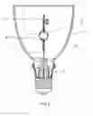
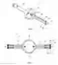
FIG. 2 shows a ceramic discharge vessel in an exploded representation, with partial cut-away;
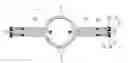
FIG. 3 shows a cross section through the discharge vessel.
PREFERRED EMBODIMENT OF THE INVENTION
FIG. 1 schematically shows a reflector lamp 1. It has a ceramic discharge vessel 2, which is fastened in a base 3, and has two electrodes 5 in the discharge volume. Feed-throughs 7 project from the discharge vessel. A reflector 4, in which the discharge vessel is arranged axially, is fastened on the base. The discharge volume contains a fill, typically of metal halides and mercury.
FIG. 2 shows the discharge vessel 2, which is essentially produced from Al2O3 and has a bulging central part 8 in which electrodes and a fill of metal halides are accommodated. Capillaries 10 integrally adjoin the central part. Feed-throughs 11, for example consisting of Mo pins or configured in several parts as known per se, are fed into these capillaries and the shafts of the electrodes are respectively welded to them. All that is essential, however, is that the rear end of the feed-through is an Mo pin. It has a diameter of typically 1 mm. The capillary 10 is followed by a cermet tube 15 consisting of typically 50 layers of films. The films are typically each 50 μm thick, with the possible exception of the first and last films which may respectively be up to 200 to 300 μm thick. A high-temperature solder 16 is introduced between the capillary and the cermet tube. A cover cap 17 made of molybdenum with an angled-off edge 18 is applied onto the outer end of the cermet tube 15, a platinum solder 19 for sealing being introduced between the cermet tube and the cover cap. The cover cap 17 is an Mo sheet with a thickness of typically from 200 to 500 μm.
The cover cap 17 is welded to the feed-through 11, which is fed through a central bore 20 of the cover cap. For better weldability of the feed-through 11, the cover cap is preferably curved outward on the inner hole 11.
Typically, a gap with a width of from 50 to 100 μm remains between the Mo feed-through 11 and the capillary 10. The same applies for the gap between the cermet tube 15 and the Mo feed-through 11.
Typical fills for such lamps are described, for example, in EP-A 587 238.
The proportion of Mo in the first layer facing toward the capillary is from 3 to 15 vol. % and in the last layer from 85 to 97 vol. %, the remainder being Al2O3. Between them, for example, there are from 30 to 100 layers with a thickness of approximately 50 μm each. The proportion of Mo increases, preferably in a constant ratio, from the first to last layers. For secure sealing, it has been found crucial that the changes in the thermal expansion coefficient from film to film in the cermet tube and at its two ends can be kept very small. With this technology, they lie in the range of a few 10−8 K−1.
In a particularly preferred embodiment, the radial layers are composed so that not only the thermal expansion coefficient is graded and matched well, but also the shrinkage behavior of the various layers is virtually the same. The grain size of the powders being used has proven crucial for satisfying this requirement.
For successful sealing, the different thermal expansion coefficients of the individual components Al2O3 as the material of the capillary, with the thermal expansion coefficient 8.3×10⁻⁶ K−1, and the Mo pin with the thermal expansion coefficient of 5×10⁻⁶ K−1, must be matched successfully to one another. This is done by means of the axial cermet component. A cermet tube consisting of Mo/Al2O3 is applied onto the end face of the Al2O3 capillary. The first layer is as rich as possible in Al2O3, in order to ensure the transition to the capillary. Outward, the Mo content always increases further. An Mo cap is preferably soldered onto the Mo-rich last outer layer. The advantages of this arrangement are:
-
- the slurry composition for producing the thin layers, which may be referred to as films, can be made in any desired Mo/Al2O3 ratio. Very fine gradings are possible, as regards the thermal expansion coefficient.
- tapes with a thickness of between 20 and 100 μm are possible for the film production. The tape thickness of the individual films determines the degree of grading in the thermal expansion coefficient in the cermet.
- the individual components of the seal can be produced separately. A modular structure is thus possible.
- a gas-tight cermet body with a graded composition is generated by the sintering. Intimate bonding takes place between the various material zones, i.e. the tapes. Cracks due to thermomechanical stresses can thereby be avoided.
- by using graded cermet structures on the ends of the capillaries, the capillaries can be made shorter. This leads to more compact discharge vessels and therefore also to lamps with a better luminous efficiency, because high temperatures can therefore also be achieved during the lamp operation.
The graded cermet is produced by means of a multilayer technology. To this end, thin films with a different Mo/Al2O3 ratio are produced, and subsequently stacked and laminated according to the increasing Mo content. Since the starting substances Mo and Al2O3 have different sintering temperatures, and therefore also exhibit different shrinkage properties, a graded multilayer stack becomes distorted during the sintering and the planar stack is finally curved. This leads in the end to delamination of individual layer composites. The trick is then to find an arrangement which exhibits a maximally uniform sintering shrinkage. This then leads to a uniform sintering shrinkage over the cross section of the graded cermet, and avoids curvature and delamination. It furthermore leads to a reduction of the intrinsic stresses in the sintered stack.
In order to achieve this, materials with different grain sizes were employed and these were mixed differently. Only in this way was it possible to adjust the target shrinkage of the individual layers, and therefore control the shrinkage of the overall graded cermet. In this context, a cermet according to Tab. 1 gives graded cermets with 18+−0.5% surface shrinkage and Tab. 2 gives graded cermets with 20+−0.5% surface shrinkage. These data relate specifically to a sintering temperature of 1900° C., over one hour in an N2 atmosphere. The cermets produced in this way retain their planar structure even after sintering, and are compact. The powders used are presented in Tab. 3. In this context, Mo-rich cermet films are generally sinter-active and must therefore be produced with a higher proportion of finer powder. Low-Mo cermet films should be produced with higher proportions of coarser powder.
Tabs 1 and 2 show in the first column the layer number and the volume proportion Mo—Al2O3 (Alox). The second column shows the structure consisting of one Mo fraction and a plurality of Al2O3 fractions with different average grain diameters d50. The next columns specify the proportions of the fractions in grams. At the end, a column with the surface shrinkage S(x,y) in percent is provided.
Tab. 3 explains the various fractions in detail. Here, it is astonishing that with a suitable choice of the average diameter of the Mo powder, it is possible to use just one Mo fraction, and that the desired properties can then be achieved with only at most two Al2O3 fractions. In this context, the selection of the possible surface shrinkage is an essential guarantee of success.
It has been found that a powder with a d50 of from 1.5 to 2.6 μm should be selected as the Mo fraction. Larger values of d50 do not achieve the object. Smaller values are also unsuitable.
It has furthermore been found that as the Al2O3 fraction a selection of powders with different d50 values must be envisaged in order simultaneously to achieve the strict requirements for a matched thermal expansion coefficient and a homogeneous surface shrinkage. A set of four different powders is used for this, the average grain diameters d50 of which range from about 0.01 to more than 1.0 μm, i.e. over two orders of magnitude. The powders specified are available from commercial suppliers, for example Degussa.
The exemplary embodiments presented, with 9 layers, can readily be adapted into exemplary embodiments having more layers, for example by additionally interpolating suitably between the compositions respectively specified.
| TABLE 1 | |||||
| Layer | Weigh-in | Weigh-in | Weigh-in | S | |
| Mo-Alox | Structure | Mo (g) | Ax6 (g) | Ax12 (g) | (x, y) |
| 1/5-95 | Mo, Ax6, Ax12 | 5.1 | 16.8 | 18.9 | 18.5 |
| 2/10-90 | Mo, Ax6, Ax12 | 10.2 | 17.4 | 20.4 | 17.8 |
| 3/20-80 | Mo, Ax6, Ax12 | 20.4 | 14.9 | 16.8 | 17.7 |
| 4/40-60 | Mo, Ax6, Ax12 | 40.9 | 19.3 | 4.5 | 18.1 |
| 5/50-50 | Mo, Ax6, Ax12 | 51.1 | 16.1 | 3.8 | 17.7 |
| 6/60-40 | Mo, Ax6, Ax12 | 61.3 | 12.9 | 3.0 | 17.8 |
| 7/80-20 | Mo, Ax6, Ax12 | 81.8 | 6.4 | 1.5 | 18.0 |
| 8/90-10 | Mo, Ax6, Ax12 | 92.0 | 3.2 | 0.8 | 18.1 |
| 9/95-5 | Mo, Ax6 | 97.1 | 1.5 | 18.0 | |
| TABLE 2 | |||||
| Layer | Weigh-in | Weigh-in | Weigh-in | S | |
| Mo-Alox | Structure | Mo (g) | Ax-1 (g) | Ax-2 (g) | (x, y) |
| 1/5-95 | Mo, Ax6, Ax12 | 5.1 | 28.6 | 9.1 | 20.0 |
| 2/10-90 | Mo, Ax15, Ax12 | 10.2 | 18.7 | 17.1 | 20.0 |
| 3/20-80 | Mo, Ax15, Ax12 | 20.4 | 19.5 | 12.3 | 20.4 |
| 4/40-60 | Mo, Ax6 | 40.9 | 23.8 | 20.1 | |
| 5/50-50 | Mo, Ax15 | 51.1 | 19.6 | 20.2 | |
| 6/60-40 | Mo, Ax15, Ax20 | 61.3 | 11.9 | 4.0 | 19.7 |
| 7/80-20 | Mo, Ax15, Ax20 | 81.8 | 4.0 | 4.0 | 20.1 |
| 8/90-10 | Mo, Ax6 | 92.0 | 4.0 | 20.1 | |
| 9/95-5 | Mo, Ax6 | 97.1 | 2.0 | 19.9 | |
| TABLE 3 | |||
| Material | Type | Grain size d50 in μm | |
| Mo | Mo | 1.5 to 2.6 | |
| Al2O3 | Ax 20 | 0.01 to 0.02 | |
| Al2O3 | Ax 15 | 0.3 to 0.4 | |
| Al2O3 | Ax 6 | 0.5 to 0.6 | |
| Al2O3 | Ax 12 | 1.0 to 1.5 | |
Claims
1. A high-pressure discharge lamp, comprising: a ceramic discharge vessel and a longitudinal axis, with electrodes respectively being led out from the discharge vessel by means of a feed-through via capillaries, wherein a tubular cermet part, which consists of individual layers of different composition layered axially in succession, is fitted on the capillary, each layer containing Mo and Al2O3, the proportion of Mo in the first layer facing toward the capillary being from 3 to 15 vol. % and in the last layer being from 85 to 97 vol. %, and a molybdenum cover cap, the cover cap being welded to the feed-through and the cover cap being connected to the cermet part by means of solder containing metal, and the connection between the capillary and the cermet part being established by means of high-melting glass solder or sinter-active Al2O3 powder.
2. The high-pressure discharge lamp as claimed in claim 1, wherein the cermet part consists of at least 5 different layers, the Mo content of which increases from the inside outward.
3. The high-pressure discharge lamp as claimed in claim 1, wherein the individual layers of the cermet part, apart from the first and last layers, are each from 20 to 100 μm thick.
4. The high-pressure discharge lamp as claimed in claim 3, wherein the layer thicknesses of these layers are each essentially equal.
5. The high-pressure discharge lamp as claimed in claim 1, wherein the outer end side of the capillary is chamfered on at least one of its inner and outer edge, and wherein the cermet part's end side facing toward the capillary is matched thereto.
6. A method for producing a tubular cermet part
the high-pressure discharge lamp comprising:
a ceramic discharge vessel and a longitudinal axis, with electrodes respectively being led out from the discharge vessel by means of a feed-through via capillaries,
wherein a tubular cermet part, which consists of individual layers of different composition layered axially in succession, is fitted on the capillary, each layer containing Mo and Al203, the proportion of Mo in the first layer facing toward the capillary being from 3 to 15 vol. % and in the last layer being from 85 to 97 vol. %, and a molybdenum cover cap, the cover cap being welded to the feed-through and the cover cap being connected to the cermet part by means of solder containing metal, and the connection between the capillary and the cermet part being established by means of high-melting glass solder or sinter-active Al203 powder
the method comprising:
producing films, respectively formed by a cermet having the components Mo and Al2O3, so that the volume fraction of Mo is between 3 and 97%;
stacking and laminating a bundle of at least 5 films, the Mo content of which increases from one film to another, a first film having an Mo content of from 3 to 15 vol. % and a last film having an Mo content of from 85 to 97 vol. %, the layer thickness of the films, apart from the first and last layers, each being from 20 to 100 μm, so that a laminate is formed;
stamping tubular parts from the laminate, which have a gradually differing Mo content along their longitudinal axis.
7. The method as claimed in claim 6,
wherein the components Mo and Al2O3 are selected so that the shrinkage behaviors of the individual films differ from one another at most by a value of 1%.
8. The method as claimed in claim 6,
wherein a powder of a uniform fraction having an average grain diameter d50 of from 1.5 to 2.6 μm is used for the component Mo.
9. The method as claimed in claim 6,
wherein a powder which is mixed together from up to four different powder fractions is used for the component Al2O3, the different fractions having different average grain diameters d50 which lie between 0.01 μm and 1.5 μm.
10. The high-pressure discharge lamp as claimed in claim 1,
wherein the molybdenum cover cap comprises a bore for the feed-through being placed on the end of the cermet part.
11. The high-pressure discharge lamp as claimed in claim 2,
wherein the cermet part consists of at least 8 different layers, the Mo content of which increases from the inside outward.
12. The high-pressure discharge lamp as claimed in claim 11,
wherein the cermet part consists of at least 30 different layers, the Mo content of which increases from the inside outward.
13. The method as claimed in claim 6,
wherein the producing films comprises producing films with a layer thickness of from 20 to 100 μm.
Images & Drawings included:
Sources:
- United States Patent and Trademark Office - verify current appl. status at the USPTO↗
Similar patent applications:
- » 20070052365
Manufacturing method of high-pressure discharge lamp, high-pressure discharge lamp, lamp unit using high-pressure discharge lamp, and image display apparatus using high-pressure discharge lamp - » 20110210680
High-pressure discharge lamp lighting device, high pressure discharge lamp apparatus using this, projector using the high-pressure discharge lamp apparatus, and high-pressure discharge lamp lighting method - » 20110121746
High-pressure discharge lamp lighting device, high-pressure discharge lamp utilizing the same, projector utilizing said high-pressure discharge lamp, and high-pressure discharge lamp lighting method - » 20110025989
High-pressure discharge lamp lighting device with current control, high-pressure discharge lamp device using same, projector using said high-pressure discharge lamp device, and high-pressure discharge lamp lighting method with current control - » 20120049764
High-pressure discharge lamp lighting device, high-pressure discharge lamp device using the same, projector using the high-pressure discharge lamp device, and lighting method for high-pressure discharge lamp - » 20110121725
Electrode for high pressure discharge lamp, high pressure discharge lamp, and method for manufacturing electrode for high pressure discharge lamptechnical field - » 20120074858
High-pressure discharge lamp light-up device, high-pressure discharge lamp apparatus using same, projector using high-pressure discharge lamp apparatus, and light-up method for high-pressure discharge lamp - » 20070296349
Method For Operation Of A High Pressure Discharge Lamp Operating Device For A High Pressure Discharge Lamp And High Pressure Discharge Lamp With An Operating Device - » 20100013399
Lighting method for a high-pressure discharge lamp, lighting circuit for a high-pressure discharge lamp, high-pressure discharge lamp apparatus, and projector-type image display apparatus - » 20060035558
Method for manufacturing high pressure discharge lamp, high pressure discharge lamp manufactured using the method, lamp unit, and image display device
Recent applications in this class:
- » 20250079148 2025-03-06
UV RADIATION SOURCE ASSEMBLY - » 20240379340 2024-11-14
METAL FIXING MATERIAL LEADTHROUGH HAVING LOW SUSCEPTIBILITY TO FAULTS - » 20240128074 2024-04-18
UV radiation source assembly - » 20230139822 2023-05-04
UV radiation source assembly - » 20220285144 2022-09-08
External electrode fluorescent lamp and home appliance including the same - » 20220059337 2022-02-24
Glass-metal feedthrough - » 20210043439 2021-02-11
Glass-metal feedthrough - » 20200027715 2020-01-23
Glass-metal feedthrough - » 20140175976 2014-06-26
High-pressure discharge lamp - » 20140062295 2014-03-06
Sealing compound and ceramic discharge vessel comprising such sealing compound
Recent applications for this Assignee:
- » 20140184060 2014-07-03
Halogen incandescent lamp for a vehicle headlight - » 20130216431 2013-08-22
Device for irradiating surfaces - » 20130201683 2013-08-08
Lighting device - » 20130194777 2013-08-01
Luminescent device for the conversion of pump light - » 20130181604 2013-07-18
High-pressure discharge lamp having a capacitive ignition aid - » 20130169158 2013-07-04
Light emitting unit driving circuit and light emitting device - » 20130154552 2013-06-20
Energy Box Having an Inductive Charger, and a Method for Charging an Energy Box - » 20130135855 2013-05-30
Illuminating system of flexible shape - » 20130130434 2013-05-23
Method for Producing a Photovoltaic Element Comprising a Silicon Dioxide Layer - » 20130119279 2013-05-16
Radiating element for irradiating surfaces, having a socket