AIRATION TYPE FLOOR CUSHION
US20100306922A1
2010-12-09
12/526,044
2007-11-26
Abstract:
A airation type floor cushion is provided, which can be placed on a chair, a seat or the floor of a room so that scrotum dampness can be prevented and pressure and massage effects can also be expected for a fresh life by aid of smooth air ventilation when men or women sit on the cushion plate.
Interested in similar patents?
Get notified when new applications in this technology area are published.
Classification:
A47C7/746 » CPC main
Parts, details, or accessories of chairs or stools; Accessories for chairs; Adaptations for incorporating lamps, radio sets, bars, telephones, ventilation, heating or cooling arrangements or the like for ventilation, heating or cooling for ventilating or cooling without active means, e.g. with openings or heat conductors
A47C3/16 » CPC further
Chairs characterised by structural features; Chairs or stools with rotatable or vertically-adjustable seats of legless type, e.g. with seat directly resting on the floor ; Hassocks; Pouffes
A47C7/021 » CPC further
Parts, details, or accessories of chairs or stools; Seat parts Detachable or loose seat cushions
A47C16/00 IPC
rests or supports for feet, legs, arms, back or head Stand-alone
Description
TECHNICAL FIELD
The present utility model relates to a airation type floor cushion which can be placed on a chair, a seat or the floor of a room so that scrotum dampness can be prevented and pressure and massage effects can also be expected for a fresh life by aid of smooth air ventilation when men or women sit on the cushion plate.
BACKGROUND ART
According to the related art, cushions made of usual fabrics, resin materials, woods or sofa fabrics were generally employed, and ventilation type cushions were also employed, however, there was no cushion plate that can carry out cool air ventilation.
DISCLOSURE
Technical Problem
In light of the above situation, it is an objective of the present utility model to provide a airation type floor cushion, which has a plurality of protrusions on both surfaces of a bottom plate and a plurality of ventilating holes punctured between the protrusions so that smooth air ventilation can be achieved, pressure and massage effects can be achieved, and easy usage without limitation to place or floor can be implemented.
Technical Solution
In one aspect, the utility model is directed to a airation type floor cushion, which includes a plurality of protrusion support tubes symmetrically formed on both surfaces of a plate and integrated with the plate; support rods protruded in the entire protrusion support tubes of the plate and to be inserted and secured to protrusions; protrusions with actually recessed portions which are inserted and secured to the support rods; a plurality of ventilating holes formed between the protrusions for achieving smooth air ventilation; and a plurality of rings formed at an outer circumference of the plate to be fixed by strings as required.
Advantageous Effects
According to the present utility model as described above, it has the following effects. When men and women sit on the cushion plate put on chair, seat or floor of the room, air can be smooth ventilated through protrusions and ventilating holes formed at both surfaces of the plate, and in particular, when men sit on the plate for a long time, scrotum dampness can be prevented and enhanced sperm activity can be expected.
DESCRIPTION OF DRAWINGS
The foregoing and other objects, features and advantages of the utility model will be apparent from the more particular description of preferred embodiments of the utility model, as illustrated in the accompanying drawings. The drawings are not necessarily to scale, emphasis instead being placed upon illustrating the principles of the utility model.
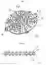
FIG. 1 is a perspective view illustrating a airation type floor cushion.
FIG. 2 is a cross-sectional view illustrating a airation type floor cushion.
FIG. 3 is a partial cross-sectional view illustrating a airation type floor cushion.
FIG. 4 is a partial disassembled view illustrating a airation type floor cushion.
BEST MODES
Hereinafter, a airation type floor cushion of the present utility model will be described with reference to the accompanying drawings.
The airation type floor cushion (A) includes a plurality of protrusion support tubes 2 and 2′ symmetrically formed on both surfaces of a plate 1 and integrated with the plate 1, support rods 5 and 5′ protruded in the entire protrusion support tubes 2 and 2′ of the plate 1 and to be inserted and secured to protrusions, protrusions 3 and 3′ with actually recessed portions 6 which are inserted and secured to the support rods, a plurality of ventilating holes 4 formed between the protrusions 3 and 3′ for achieving smooth air ventilation, and a plurality of rings 8, 8′, 8″, 8″′ formed at an outer circumference of the plate 1 to be fixed by strings as required.
A preferred embodiment of the present utility model has been disclosed herein and, although specific terms are employed, they are used and are to be interpreted in a generic and descriptive sense only and not for purpose of limitation. Accordingly, it will be understood by those of ordinary skill in the art that various changes in form and details may be made without departing from the spirit and scope of the present utility model as set forth in the following claims.
Claims
1. A airation type floor cushion, comprising:
a plurality of protrusion support tubes 2 and 2′ symmetrically formed on both surfaces of a plate 1 and integrated with the plate 1;
support rods 5 and 5′ protruded in the entire protrusion support tubes 2 and 2′ of the plate 1 and to be inserted and secured to protrusions;
protrusions 3 and 3′ with actually recessed portions 6 which are inserted and secured to the support rods;
a plurality of ventilating holes 4 formed between the protrusions 3 and 3′ for achieving smooth air ventilation;
and a plurality of rings 8, 8′, 8″, 8″′ formed at an outer circumference of the plate 1 to be fixed by strings as required.
Images & Drawings included:


Sources:
- United States Patent and Trademark Office - verify current appl. status at the USPTO↗
Recent applications in this class:
- » 20250151914 2025-05-15
VARIABLE TEMPERATURE LAWN CHAIR DEVICE - » 20240172873 2024-05-30
CUSHION BODY - » 20210127842 2021-05-06
Breathable cushion - » 20200146455 2020-05-14
SEAT PAD - » 20190298072 2019-10-03
Seat back and cushion ventilation assembly - » 20180279791 2018-10-04
Seat fitted with garnish - » 20180140101 2018-05-24
Cushion apparatus having a resilient spring member - » 20170086593 2017-03-30
Seating sofa with laminated readily reboundable cooling-effect seating cushions - » 20160220028 2016-08-04
Seat with ventilative property - » 20140008945 2014-01-09
Cool Seat