Ejection nozzle assembly
US20100309261A1
2010-12-09
12/857,357
2010-08-16
✅ Patent granted
US 7,950,777 B2
2011-05-31
-
-
An H Do
2030-08-16
Abstract:
An ejection nozzle assembly is provided having a substrate defining a fluid supply passage, drive circuitry on the substrate, a chamber on the drive circuitry and in fluid communication with the fluid supply passage and an ejection port, an ejection member disposed between the fluid supply passage and the ejection port, and a heater element electrically coupled to the drive circuitry and the ejection member for causing ejection of fluid from the ejection port.
Assignee:
- Silverbrook Research Pty Ltd 3,043 🇦🇺 Balmain, New South Wales, Australia
Interested in similar patents?
Get notified when new applications in this technology area are published.
Classification:
B41J2/14427 » CPC main
Typewriters or selective printing mechanisms characterised by the printing or marking process for which they are designed characterised by bringing liquid or particles selectively into contact with a printing material; Ink jet; Nozzles; Structure thereof only for on-demand ink jet heads Structure of ink jet print heads with thermal bend detached actuators
B41J2/1601 » CPC further
Typewriters or selective printing mechanisms characterised by the printing or marking process for which they are designed characterised by bringing liquid or particles selectively into contact with a printing material; Ink jet; Nozzles; Production of nozzles Production of bubble jet print heads
B41J2/1623 » CPC further
Typewriters or selective printing mechanisms characterised by the printing or marking process for which they are designed characterised by bringing liquid or particles selectively into contact with a printing material; Ink jet; Nozzles; Production of nozzles manufacturing processes bonding and adhesion
B41J2/1626 » CPC further
Typewriters or selective printing mechanisms characterised by the printing or marking process for which they are designed characterised by bringing liquid or particles selectively into contact with a printing material; Ink jet; Nozzles; Production of nozzles manufacturing processes etching
B41J2/1631 » CPC further
Typewriters or selective printing mechanisms characterised by the printing or marking process for which they are designed characterised by bringing liquid or particles selectively into contact with a printing material; Ink jet; Nozzles; Production of nozzles manufacturing processes photolithography
B41J2/1632 » CPC further
Typewriters or selective printing mechanisms characterised by the printing or marking process for which they are designed characterised by bringing liquid or particles selectively into contact with a printing material; Ink jet; Nozzles; Production of nozzles manufacturing processes machining
B41J2/1635 » CPC further
Typewriters or selective printing mechanisms characterised by the printing or marking process for which they are designed characterised by bringing liquid or particles selectively into contact with a printing material; Ink jet; Nozzles; Production of nozzles manufacturing processes dividing the wafer into individual chips
B41J2/1637 » CPC further
Typewriters or selective printing mechanisms characterised by the printing or marking process for which they are designed characterised by bringing liquid or particles selectively into contact with a printing material; Ink jet; Nozzles; Production of nozzles manufacturing processes molding
B41J2/1648 » CPC further
Typewriters or selective printing mechanisms characterised by the printing or marking process for which they are designed characterised by bringing liquid or particles selectively into contact with a printing material; Ink jet; Nozzles; Production of nozzles Production of print heads with thermal bend detached actuators
B41J2/17513 » CPC further
Typewriters or selective printing mechanisms characterised by the printing or marking process for which they are designed characterised by bringing liquid or particles selectively into contact with a printing material; Ink jet characterised by ink handling; Ink supply systems ; Circuit parts therefor; Ink cartridges Inner structure
B41J2/17596 » CPC further
Typewriters or selective printing mechanisms characterised by the printing or marking process for which they are designed characterised by bringing liquid or particles selectively into contact with a printing material; Ink jet characterised by ink handling; Ink supply systems ; Circuit parts therefor Ink pumps, ink valves
B82Y30/00 » CPC further
Nanotechnology for materials or surface science, e.g. nanocomposites
G06K1/121 » CPC further
Methods or arrangements for marking the record carrier in digital fashion otherwise than by punching by printing code marks
G06K7/14 » CPC further
Methods or arrangements for sensing record carriers, e.g. for reading patterns by electromagnetic radiation, e.g. optical sensing; by corpuscular radiation using light without selection of wavelength, e.g. sensing reflected white light
G06K7/1417 » CPC further
Methods or arrangements for sensing record carriers, e.g. for reading patterns by electromagnetic radiation, e.g. optical sensing; by corpuscular radiation using light without selection of wavelength, e.g. sensing reflected white light; Methods for optical code recognition the method being specifically adapted for the type of code 2D bar codes
G06K19/06037 » CPC further
Record carriers for use with machines and with at least a part designed to carry digital markings characterised by the kind of the digital marking, e.g. shape, nature, code with optically detectable marking multi-dimensional coding
G11C11/56 » CPC further
Digital stores characterised by the use of particular electric or magnetic storage elements; Storage elements therefor using storage elements with more than two stable states represented by steps, e.g. of voltage, current, phase, frequency
H04N1/2154 » CPC further
Scanning, transmission or reproduction of documents or the like, e.g. facsimile transmission; Details thereof; Intermediate information storage for one or a few pictures using still video cameras the still video camera incorporating a hardcopy reproducing device, e.g. a printer
H04N5/225 » CPC further
Details of television systems; Studio circuitry; Studio devices; Studio equipment ; Cameras comprising an electronic image sensor, e.g. digital cameras, video cameras, TV cameras, video cameras, camcorders, webcams, camera modules for embedding in other devices, e.g. mobile phones, computers or vehicles Television cameras ; Cameras comprising an electronic image sensor, e.g. digital cameras, video cameras, camcorders, webcams, camera modules specially adapted for being embedded in other devices, e.g. mobile phones, computers or vehicles
H04N5/2628 » CPC further
Details of television systems; Studio circuitry; Studio devices; Studio equipment ; Cameras comprising an electronic image sensor, e.g. digital cameras, video cameras, TV cameras, video cameras, camcorders, webcams, camera modules for embedding in other devices, e.g. mobile phones, computers or vehicles; Studio circuits, e.g. for mixing, switching-over, change of character of image, other special effects ; Cameras specially adapted for the electronic generation of special effects Alteration of picture size, shape, position or orientation, e.g. zooming, rotation, rolling, perspective, translation
B41J2/16585 » CPC further
Typewriters or selective printing mechanisms characterised by the printing or marking process for which they are designed characterised by bringing liquid or particles selectively into contact with a printing material; Ink jet; Nozzles; Preventing or detecting of nozzle clogging, e.g. cleaning, capping or moistening for nozzles for paper-width or non-reciprocating print heads
B41J2002/041 » CPC further
Typewriters or selective printing mechanisms characterised by the printing or marking process for which they are designed characterised by bringing liquid or particles selectively into contact with a printing material; Ink jet characterised by the jet generation process generating single droplets or particles on demand Electromagnetic transducer
B41J2202/21 » CPC further
Embodiments of or processes related to ink-jet or thermal heads; Embodiments of or processes related to ink-jet heads Line printing
H04N2101/00 » CPC further
Still video cameras
B41J2/05 IPC
Typewriters or selective printing mechanisms characterised by the printing or marking process for which they are designed characterised by bringing liquid or particles selectively into contact with a printing material; Ink jet characterised by the jet generation process generating single droplets or particles on demand by pressure, e.g. electromechanical transducers produced by the application of heat
Description
CROSS REFERENCES TO RELATED APPLICATIONS
The present application is a Continuation of U.S. Application Ser. No. 12/368,997 filed Feb. 11, 2009, which is a Continuation of U.S. Application Ser. No. 11/707,039 filed 16 Feb. 2007, now issued U.S. Pat. No. 7,506,969, which is a Continuation of U.S. Application Ser. No. 11/484,745 filed on Jul. 12, 2006, now issued as U.S. Pat. No. 7,195,339, which is a Continuation of U.S. Application Ser. No. 11/185,721 filed on July 21, 2005, now issued as U.S. Pat. No. 7,083,263, which is a Continuation of U.S. Application Ser. No. 10/713,084 filed on Nov. 17, 2003, now issued as U.S. Pat. No. 7,066,574, which is a Continuation of U.S. Application Ser. No. 10/401,987 filed on Mar. 31, 2003, now issued as U.S. Pat. No. 6,663,225, which is a Continuation of U.S. Application Ser. No. 09/864,332 filed on May 25, 2001, now issued as U.S. Pat. No. 6,540,331, which is a Continuation-In-Part of U.S. Application Ser. No. 09/112,767 filed on Jul. 10, 1998, now issued as U.S. Pat. No. 6,416,167, the entire contents of which are herein incorporated by reference.
FIELD OF THE INVENTION
This invention relates to a micro-electromechanical device having actuator guide formations.
BACKGROUND OF THE INVENTION
The applicant has invented a page width printhead which is capable of generating text and images of a resolution as high as 1600 dpi.
The printheads are manufactured in accordance with a technique that is based on integrated circuit fabrication. An example of such a technique is that which is presently used for the fabrication of micro-electromechanical systems.
These fabrication techniques allow the printhead to incorporate up to 84000 nozzle arrangements. The nozzle arrangements are electromechanically operated to achieve the ejection of ink.
In a number of the Applicant's inventions, the nozzle arrangements incorporate thermally actuated devices which are displaceable within nozzle chambers to eject the ink from the nozzle chambers. Many of the thermal actuators use a combination of materials and a bending action which results from an uneven expansion of the materials. The thermal actuators are manufactured by depositing consecutive layers of material having different coefficients of thermal expansion.
The present invention was conceived to address certain problems associated with such actuators. A significant problem with such actuators is that the different materials can result in bending and bending stresses being set up in the thermal actuator when the thermal actuator is inoperative and exposed to transient conditions. As is known in the field of integrated circuit fabrication, the deposition of material results in a heating of both the material being deposited and the material on which the deposition takes place. The fact that the materials have different thermal expansion characteristics can result in the bending of the laminated structure upon cooling. This is also the case where the materials have different elasticity characteristics. Those skilled in the field of micro electro-mechanical systems fabrication will appreciate that this is highly undesirable.
SUMMARY OF THE INVENTION
According to a first aspect of the invention, there is provided a micro-electromechanical device which comprises
-
- a substrate containing drive circuitry; and
- an elongate actuator that is fast with the substrate at a fixed end, the elongate actuator having a laminated structure of at least one inner layer and a pair of opposed, outer layers, the outer layers having substantially the same thermal expansion and elasticity characteristics, with one of the outer layers defining an electrical heating circuit that is in electrical contact with the drive circuitry to be heated and to expand on receipt of an electrical signal from the drive circuitry and to cool and contract on termination of the signal, thereby to generate reciprocal movement of the actuator.
The actuator may have a single inner layer.
The outer layers may have a higher coefficient of thermal expansion than the inner layer.
According to a second aspect of the invention, there is provided a micro-electromechanical device which comprises
a substrate containing drive circuitry; and
a plurality of elongate actuators, each actuator being fast with the substrate at a fixed end, each elongate actuator having a laminated structure of at least three layers in the form of a pair of opposed, outer layers and at least one inner layer, the outer layers having substantially the same thermal expansion and elasticity characteristics, with one of the outer layers defining an electrical heating circuit that is in electrical contact with the drive circuitry to be heated and to expand on receipt of an electrical signal from the drive circuitry and to cool and contract on termination of the signal, thereby to generate reciprocal movement of the actuator.
According to a third aspect of the invention, there is provided a fluid ejecting device which comprises
a substrate containing drive circuitry,
nozzle chamber walls and a roof wall positioned on the substrate to define a nozzle chamber in which fluid is received and a fluid ejection port from which the fluid is ejected, in use;
a fluid ejecting mechanism that is operatively arranged with respect to the nozzle chamber to act on the fluid in the nozzle chamber to eject fluid from the fluid ejection port;
a thermal bend actuator that is connected to the drive circuitry to receive an electrical signal from the drive circuitry and to provide actuation of the fluid ejecting mechanism, wherein
the thermal bend actuator has a laminated structure of at least three layers in the form of a pair of opposed, outer layers and at least one inner layer, the outer layers having substantially the same thermal expansion and elasticity characteristics.
The thermal bend actuator may have a single inner layer.
The outer layers of the thermal bend actuator may each be conductive.
At least one of the outer layers of the thermal bend actuator may be connected to the drive circuitry so that said at least one of the outer layers can be heated.
The outer layers may have a higher coefficient of thermal expansion than the inner layer.
BRIEF DESCRIPTION OF THE DRAWINGS
In the drawings,
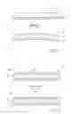
FIG. 1 shows two conditions of a thermal bend actuator of a fluid ejection device, not in accordance with the invention, and indicating the problem associated with such thermal bend actuators;
FIG. 2 shows a schematic view of a thermal bend actuator of a fluid ejection device, in accordance with the invention, and, in particular, the advantage associated with such a thermal bend actuator; and
FIG. 3 shows a fluid ejection device in accordance with the invention.
DETAILED DESCRIPTION OF THE INVENTION
In FIG. 1, reference numeral 10 generally indicates an actuating mechanism in the form of a bi-layer thermal bend actuator.
As set out above, the device in which the thermal bend actuator 10 is to be incorporated is formed as part of an integrated circuit fabrication process. It follows that the thermal actuator 10 is manufactured in a deposition and etching process. Thus, once a first layer 12 has been deposited and prepared, a second layer 14 is deposited on the first layer 12. In order to operate correctly, one of the layers, in this case the first layer 14 is of a material having a higher coefficient of thermal expansion than the material of the second layer 12.
As is well known in the field of integrated circuit fabrication, deposition of material occurs at a temperature which is, of necessity, significantly higher than ambient temperature. This results in a heating of the first layer 12 and the deposited second layer 14.
Also, in order to operate, the layers 12, 14 are of materials which have different coefficients of thermal expansion. It follows that, upon cooling after deposition, thermal stresses are set up between the layers 12, 14 which can cause bending of the actuator 10. This is extremely undesirable, particularly in light of the fact that the actuators are manufactured on a micro-electromechanical scale.
In FIG. 2, reference numeral 20 generally indicates an actuator mechanism of a fluid ejection device, in accordance with the invention.
The actuator mechanism 20 includes a thermal bend actuator 22 which has three layers in the form of a pair of opposed outer layers 24 and an inner layer 26.
The outer layers 24 are of substantially the same material and are of substantially the same dimensions. Further, the outer layers 24 are each conductive.
The outer layers 24 are of a material having a coefficient of thermal expansion which is such that, upon heating of any one of the layers 24, the actuator 22 bends to a degree sufficient to perform work. In particular, the outer layers 24 can be of any material having a suitable Young's modulus and coefficient of thermal expansion. Possible materials are titanium nitride and a copper nickel alloy.
The inner layer 26 can be any suitable insulating material such as glass (amorphous silicon dioxide) or even air.
It will be appreciated that the thermal bend actuator 22 will find application in any micro electro-mechanical system in which a prime mover is required. Thus, at least one of the outer layers 24 is connectable to drive circuitry of such a micro electro-mechanical device.
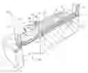
In FIG. 3, reference numeral 30 generally indicates a fluid ejection device in accordance with the invention. In this embodiment, the fluid ejection device is in the form of a nozzle arrangement of an ink jet printhead, which includes the actuating mechanism 20.
It is to be appreciated that reference to the nozzle arrangement 30 is for illustrative purposes and should not be construed as limiting the invention to this particular embodiment.
The nozzle arrangement 30 is formed on a wafer substrate 32 in a successive deposition and etching process which forms part of an integrated circuit fabrication technique conventionally used in the manufacture of micro electro-mechanical systems.
In this particular example, the nozzle arrangement 30 is formed on a drive circuitry layer 34 which, itself, is formed on the wafer substrate 32.
A support post 36 extends from the drive circuitry layer 34. The thermal bend actuator 22 is mounted, cantilever-fashion, on the support post 36. One of the outer layers 24 is in electrical contact with the drive circuitry layer 34 so that movement of the bend actuator 22 can be achieved with a control system (not shown) connected to the drive circuitry layer 34.
A cylindrical wall 38 is formed on the drive circuitry layer 34 to define a nozzle chamber 40. A roof wall 42 is arranged on the cylindrical wall 38 and defines an ink ejection port 44 from which ink is ejected out of the nozzle chamber 40. An ink ejection member 46 is mounted on the thermal bend actuator 22 and extends through a slot 48 defined in the cylindrical wall 38. The ink ejection member 46 includes an arm 50 and a paddle 52 mounted on the arm 50 and being shaped to correspond generally with a cross-sectional dimension of the nozzle chamber 40.
The slot 48 in the cylindrical wall 38 is shaped to define a guide formation 54 in the cylindrical wall 38. An end of the arm 50 on which the paddle 52 is mounted is shaped to correspond with the guide formation 54. In particular, the guide formation 54 and the end 56 of the arm 50 are shaped so that, on bending of the bend actuator 22, movement of the end 56 and hence the paddle 52 is retained along a linear path.
The nozzle arrangement 30 is one of a plurality of nozzle arrangements formed on the wafer substrate 32 to define the ink jet printhead of the invention. It is simply for reasons of clarity and ease of description that a single nozzle arrangement is shown in the accompanying drawings.
It will be appreciated that, due to the fact that each nozzle arrangement is a micro-electromechanical device and that up to 84000 such nozzle arrangements may be required for a single printhead, accuracy and consistency of manufacture of each nozzle arrangement is extremely important. It would therefore be highly disadvantageous if, upon cooling after deposition, the thermal bend actuator 22 became bent or warped. This would result in an uneven positioning of the paddles 52 within the nozzle chambers 40.
Applicant submits that the fact that the two opposed outer layers 24 have the same thermal expansion and elasticity characteristics results in stability of the bend actuator 22 upon cooling after deposition. In this manner, consistently straight bend actuators 22 can be achieved.
A further advantage that has been identified by the Applicant is that, in general operation, the substantially identical outer layers 24 of the thermal actuator 22 provide a high level of thermal stability. This allows the thermal actuator 22 to be operated repeatedly in spite of the fact that all the heat from previous activations has not yet dissipated.
Claims
1. An ejection nozzle assembly comprising:
a substrate defining a fluid supply passage;
drive circuitry on the substrate;
a chamber on the drive circuitry and in fluid communication with the fluid supply passage and an ejection port;
an ejection member disposed between the fluid supply passage and the ejection port; and
a heater element electrically coupled to the drive circuitry and the ejection member for causing ejection of fluid from the ejection port.
2. An ejection nozzle assembly as claimed in claim 1, wherein the heater element comprises titanium nitride or copper nickel alloy material.
3. An ejection nozzle assembly as claimed in claim 1, further comprising an insulating element defined on the heater element, the insulating element comprising one of glass, amorphous silicon dioxide and any other like thermal insulating material.
4. An ejection nozzle assembly as claimed in claim 1, wherein the chamber comprises a cylindrical wall and a cover that defines the ejection port.
Images & Drawings included:

Sources:
- United States Patent and Trademark Office - verify current appl. status at the USPTO↗
Similar patent applications:
- » 20220314248
Nozzle assembly, ejecting device and ejecting method - » 20080309693
Nozzle assembly for ejecting small droplets - » 20090141089
Ink jet nozzle assembly having layered ejection actuator - » 20070011876
Method of manufacturing an inkjet nozzle assembly for volumetric ink ejection - » 20120105552
Inkjet nozzle assembly having displaceable roof defining ejection port - » 20080303871
Nozzle assembly for an inkjet printer for ejecting a low volume droplet - » 20060001702
Micro-electromechanical fluid ejection device with an array of nozzle assemblies incorporating fluidic seals - » 20080303866
Nozzle assembly for an inkjet printer for ejecting a low speed droplet - » 20090159319
Resin ejection nozzle, resin encapsulation method, and electronic part assembly - » 20060268070
Inkjet printhead integrated circuit having nozzle assemblies with a bubble collapse point close to ink ejection aperture
Recent applications in this class:
- » 20250269646 2025-08-28
LIQUID JET HEAD AND LIQUID JET RECORDING APPARATUS - » 20220339937 2022-10-27
Ink-jet head - » 20220242122 2022-08-04
Thermal bend actuator having improved lifetime - » 20200276817 2020-09-03
Liquid ejecting unit and liquid ejecting apparatus - » 20180207934 2018-07-26
INKJET PRINTING METHOD, AND ASSEMBLY FOR CARRYING OUT THE METHOD - » 20170341395 2017-11-30
Liquid ejecting apparatus - » 20160339703 2016-11-24
Thermal inkjet printhead - » 20160288504 2016-10-06
Fluid ejection device for depositing a discrete quantity of fluid onto a surface - » 20160059561 2016-03-03
Address architecture for fluid ejection chip - » 20160059560 2016-03-03
Chip layout to enable multiple heater chip vertical resolutions
Recent applications for this Assignee:
- » 20120141040 2012-06-07
Method of compressing sequence of strokes - » 20120140280 2012-06-07
Electronically transmitted document delivery through interaction with printed document - » 20120118965 2012-05-17
Process for decoding coded data - » 20120111939 2012-05-10
Transaction recordal method - » 20120104089 2012-05-03
Electronic pen for interacting with substrate - » 20120083252 2012-04-05
Messaging via a coded business card and mobile telephone - » 20120062953 2012-03-15
Application for generating interactive document containing advertising material - » 20120057919 2012-03-08
Pen-shaped printing device - » 20120056003 2012-03-08
Substrate having coding pattern encoding Reed-Solomon symbols - » 20120044186 2012-02-23
Handheld display device having processor for rendering display output with real-time virtual transparency and form-filling option