Handle for pails
US20100319161A1
2010-12-23
12/818,252
2010-06-18
✅ Patent granted
US 8,490,251 B2
2013-07-23
-
-
Chuck Y. Mah
Carlson, Gaskey & Olds
2030-10-17
Abstract:
A handle includes a bottom wall and two side walls extending up from the bottom wall. Ribs extend between the walls and define upwardly open recesses. The smooth surfaces of the side walls and bottom wall provide a more comfortable handle for the user.
Assignee:
- REHRIG PACIFIC COMPANY 306 🇺🇸 Los Angeles, CA, United States
Applicant:
Interested in similar patents?
Get notified when new applications in this technology area are published.
Classification:
B25G1/102 » CPC main
Handle constructions characterised by material or shape the shape being specially adapted to facilitate handling or improve grip
B65D25/32 » CPC further
Details of other kinds or types of rigid or semi-rigid containers; Handles Bail handles, i.e. pivoted handles of generally semi-circular shape
Y10T16/44 » CPC further
Miscellaneous hardware [e.g., bushing, carpet fastener, caster, door closer, panel hanger, attachable or adjunct handle, hinge, window sash balance, etc.] Handle, handle component, or handle adjunct
Y10T16/455 » CPC further
Miscellaneous hardware [e.g., bushing, carpet fastener, caster, door closer, panel hanger, attachable or adjunct handle, hinge, window sash balance, etc.]; Handle, handle component, or handle adjunct Luggage-type [loop style] handgrip for carrying [e.g., suitcase, handbag, briefcase, shopping bag, package, etc.]
Y10T16/469 » CPC further
Miscellaneous hardware [e.g., bushing, carpet fastener, caster, door closer, panel hanger, attachable or adjunct handle, hinge, window sash balance, etc.]; Handle, handle component, or handle adjunct Detachable handle
Y10T16/4707 » CPC further
Miscellaneous hardware [e.g., bushing, carpet fastener, caster, door closer, panel hanger, attachable or adjunct handle, hinge, window sash balance, etc.]; Handle, handle component, or handle adjunct; Detachable handle for container
Y10T16/513 » CPC further
Miscellaneous hardware [e.g., bushing, carpet fastener, caster, door closer, panel hanger, attachable or adjunct handle, hinge, window sash balance, etc.]; Insulated handle Loop-type handle
B25G1/00 IPC
Handle constructions
A47J45/07 IPC
Devices for fastening or gripping kitchen utensils or crockery; Handles for hollow-ware articles of detachable type
A45C13/26 IPC
Details; Accessories Special adaptations of handles
Description
This application claims priority to U.S. Provisional Applications Ser. Nos. 61/218,336 and 61/261,400 filed Jun. 18, 2009 and Nov. 16, 2009, respectively.
BACKGROUND
The present invention relates generally to plastic handles, such as for pails.
Plastic handles, such as for pails, often include a handle portion with straps extending from either end of the handle portion. The handle portion has a larger diameter than the straps, often by including ribs extending radially outward. The ribs make the handle less comfortable for the user's hand. Sometimes the handle has one flat surface, but there is still pressure on the user's hand from ribs in the handle portion, which is not comfortable when carrying a heavy load.
SUMMARY
A handle includes a bottom wall continuous with two side walls. A plurality of ribs extend between the walls and define upwardly open recesses. These side walls and bottom wall provide a smooth surface for the main contact areas of the user's hand. Most of the weight and pressure on the user's hand will be with the smooth surfaces, not with free ends of the ribs.
BRIEF DESCRIPTION OF THE DRAWINGS
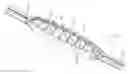
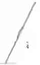
FIG. 1 is a perspective view of a handle according to a first embodiment of the present invention.
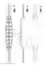
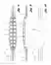
FIG. 2 is an enlarged view of the handle portion of the FIG. 1.
FIG. 3 is top view of the handle portion of FIG. 2.
FIG. 4 is a side view of the handle portion of FIG. 2.
FIG. 5 is a bottom view of the handle portion of FIG. 2.
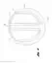
FIG. 6 is a section view through the handle portion of FIG. 2.
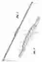
FIG. 7 is a perspective view of a handle according to a second embodiment of the present invention.
FIG. 8 is a top view of the handle portion of the handle of FIG. 7.
FIG. 9 is a side view of the handle portion of FIG. 8.
FIG. 10 is a bottom view of the handle portion of FIG. 8.
DESCRIPTION OF PREFERRED EMBODIMENTS
A handle 10 according to one embodiment of the present invention is shown in FIGS. 1-6. Referring to FIG. 1, the handle 10 includes a handle portion 12 and straps 14 extending from either longitudinal end of the handle portion 12. Each strap 14 terminates in a connector portion 16, such as a standard snap-in type rotatable connector 16. The handle portion 12, straps 14 and connector 16 are integrally molded as a single piece of a polymer.
FIG. 2 is an enlarged view of the handle portion 12 of FIG. 1. As shown, the handle portion 12 includes side walls 18 and a longitudinal divider rib 20 with transverse lateral ribs 22 connecting the two side walls 18. The side walls 18, longitudinal divider rib 20 and lateral ribs 22 define upwardly open recesses 24. The recesses 24 are defined by coring in the molds, i.e. the parting line of the handle 10 can be parallel to the straps 14, i.e. perpendicular to the dividers 20, 22, with slides to form the connectors 16. Alternatively, the parting line can be perpendicular to the straps 14, with slides to form the recesses 24.
Referring to FIG. 3, the handle portion 12 further includes a bottom wall 26 continuous with the side walls 18.
Referring to FIG. 6, this provides a continuous surface for the user's hand (side walls 18 and bottom wall 26) on the main contact surfaces. The side walls 18 are more than half the height of the handle 10 and curve inwardly toward one another. The side walls 18 extend upward past a point of the maximum diameter of the handle portion 12 and then curve inward toward one another. Alternatively, the side walls 18 and bottom wall 26 can be considered one continuous wall extending circumferentially around more than 180° of the handle portion 12. This provides a more comfortable and stable handle for the user, particularly when carrying a heavy pail.
A handle 110 according to a second embodiment of the present invention is shown in FIGS. 7-10. Referring to FIG. 7, the handle 110 includes a handle portion 112 and straps 114 extending from either longitudinal end of the handle portion 112. Each strap 114 terminates in a connector portion 116, such as a standard snap-in type rotatable connector 116. The handle portion 112, straps 14 and connector 116 are integrally molded as a single piece of a polymer.
FIG. 8 is an enlarged view of the handle portion 112 of FIG. 7. As shown, the handle portion 112 includes side walls 118 and a longitudinal divider rib 120 with transverse lateral ribs 122 connecting the two side walls 118. The side walls 118, longitudinal divider rib 120 and lateral ribs 122 define upwardly open recesses. The recesses are defined by coring in the molds, i.e. the parting line of the handle 110 can be parallel to the straps 114, i.e. perpendicular to the dividers 120, 122, with slides to form the connectors 116. Alternatively, the parting line can be perpendicular to the straps 114, with slides to form the recesses.
In this embodiment, the longitudinal divider rib 120 includes a tapered portion 121 at each end of the handle portion 112, visible in FIGS. 8 and 9, that tapers continuously into a small vertical rib 115 extending substantially the entire length of the strap 114. The vertical rib 115 may project from one or both surfaces of the strap 114.
Referring to FIG. 10, the handle portion 112 further includes a bottom wall 126 continuous with the side walls 18.
The handle 110 provides a continuous surface for the user's hand (side walls 118 and bottom wall 126) on the main contact surfaces. The side walls 118 are more than half the height of the handle 110. Alternatively, the side walls 118 and bottom wall 126 can be considered one continuous wall extending circumferentially around more than 180° of the handle portion 112. This provides a more comfortable and stable handle for the user, particularly when carrying a heavy pail. The handle portion 112 would have the same cross section as FIG. 6.
In accordance with the provisions of the patent statutes and jurisprudence, exemplary configurations described above are considered to represent a preferred embodiment of the invention. However, it should be noted that the invention can be practiced otherwise than as specifically illustrated and described without departing from its spirit or scope.
Claims
What is claimed is:1. A handle comprising:
a bottom wall;
a pair of opposed side walls extending upward from the bottom wall; and
a plurality of ribs extending between the side walls and bottom wall defining upwardly open recesses.
2. The handle of claim 1, wherein the side walls are more than half the height of the handle.
3. The handle of claim 1, wherein the side walls are curved inwardly toward one another and extend upward past a point of maximum diameter of the handle.
4. The handle of claim 1, wherein the side walls and bottom wall extend continuously circumferentially around more than 180° of the handle.
5. The handle of claim 1, wherein the bottom wall and side walls define a handle portion, the handle further including straps extending from either longitudinal end of the handle portion, wherein the straps are integrally molded with the handle portion.
6. The handle of claim 5, further including an integrally molded connector at each end of each strap.
7. The handle of claim 5 wherein the plurality of ribs includes a longitudinal divider rib that includes a tapered portion at each end of the handle portion that tapers continuously into a vertical rib on each strap.
8. A handle comprising:
a handle portion including a bottom wall and a pair of opposed side walls extending upward from the bottom wall, wherein the side walls and bottom wall extend continuously circumferentially around more than 180° of the handle; and
a strap extending from each longitudinal end of the handle portion, wherein the straps are integrally molded with the handle portion.
9. The handle of claim 8, wherein the side walls are more than half the height of the handle portion.
10. The handle of claim 9, wherein the side walls are curved inwardly toward one another and extend upward past a point of maximum diameter of the handle.
11. The handle of claim 10, further including an integrally molded connector at each end of each strap.
Images & Drawings included:
Sources:
- United States Patent and Trademark Office - verify current appl. status at the USPTO↗
Similar patent applications:
- » 20050241114
Pail handle
Recent applications in this class:
- » 20250289114 2025-09-18
STABILIZING DEVICE FOR HOLDING A LONG HANDLE TOOL IN AN UPRIGHT POSITION - » 20250289113 2025-09-18
APPARATUS - » 20250205869 2025-06-26
OFFSET HAMMER HANDLE - » 20250135625 2025-05-01
ERGONOMIC HOLDERS FOR HAND TOOLS - » 20250091193 2025-03-20
ERGONOMIC MANUAL DRIVER - » 20250018551 2025-01-16
MOP HANDLE WITH GRIP - » 20240408739 2024-12-12
ANTI-PINCH DEVICE FOR INSULATING IMPLEMENTATIONS - » 20240399558 2024-12-05
Ergonomic Grip for Knife - » 20240391083 2024-11-28
GRIPPING TOOL - » 20240375261 2024-11-14
ROTARY KNIFE HANDLE WITH KNUCKLE FASTENING
Recent applications for this Assignee:
- » 20240124178 2024-04-18
Pallet wrapper and imaging system - » 20230360419 2023-11-09
Delivery system - » 20230278612 2023-09-07
Adjustable span tine pallet jack - » 20230150560 2023-05-18
Delivery systems for ramps or stairs - » 20230140119 2023-05-04
Delivery system - » 20230078746 2023-03-16
Hybrid collapsible crate - » 20230059103 2023-02-23
Pallet wrapper and imaging system - » 20230054508 2023-02-23
Imaging system with unsupervised learning - » 20230010597 2023-01-12
Locking mechanism for container - » 20220324640 2022-10-13
Attached lid container with RFID tag