Linear motor armature and linear motor
US20100320847A1
2010-12-23
12/813,460
2010-06-10
✅ Patent granted
US 8,179,001 B2
2012-05-15
-
-
Dang Le
2031-01-19
Abstract:
A linear motor armature includes a plurality of armature core blocks that are linearly connected to each other, each armature core block being formed of a stack of a plurality of armature cores that are substantially I-shaped, each armature core block including teeth portions around which armature coils are wound, the teeth portions being provided in two end portions of the armature core block in a longitudinal direction of the armature core block, and a step portion extending in a direction perpendicular to the longitudinal direction of the armature core block, the step portion being provided at a center of the armature core block and having a width larger than a width of the teeth portions, wherein an attachment hole for fixing each of the plurality of armature core blocks to an external armature attachment plate is formed in each of two side portions of the step portion.
Inventors:
- Masanobu Kakihara 12 🇯🇵 Fukuoka, Japan
- Motomichi OHTO 10 🇯🇵 Fukuoka, Japan
- Toru Shikayama 17 🇯🇵 Fukuoka, Japan
- Motomichi Ohto 9 🇯🇵 Kitakyushu, Japan
- Toru Shikayama 11 🇯🇵 Kitakyushu, Japan
- Masanobu Kakihara 10 🇯🇵 Kitakyushu, Japan
Assignee:
- KABUSHIKI KAISHA YASKAWA DENKI 1,133 🇯🇵 Kitakyushu-shi, Japan
- KABUSHIKI KAISHA YASKAWA DENKI 268 🇯🇵 Fukuoka, Japan
Interested in similar patents?
Get notified when new applications in this technology area are published.
Classification:
H02K1/18 » CPC further
Details of the magnetic circuit characterised by the shape, form or construction; Stationary parts of the magnetic circuit Means for mounting or fastening magnetic stationary parts on to, or to, the stator structures
H02K41/03 » CPC main
Propulsion systems in which a rigid body is moved along a path due to dynamo-electric interaction between the body and a magnetic field travelling along the path; Linear motors; Sectional motors Synchronous motors; Motors moving step by step; Reluctance motors
H02K41/02 IPC
Propulsion systems in which a rigid body is moved along a path due to dynamo-electric interaction between the body and a magnetic field travelling along the path Linear motors; Sectional motors
Description
CROSS-REFERENCE TO RELATED APPLICATION
The present application is related to Japanese Patent applications no. 2009-146948, filed Jun. 19, 2009. The contents of these applications are incorporated herein by reference in their entirety.
DESCRIPTION OF THE RELATED ART
The present invention relates to a linear motor armature and a linear motor.
A linear motor armature and a linear motor are used, for example, for moving a table in a semiconductor manufacturing apparatus or a machine tool. In this technical field, Japanese Unexamined Patent Application Publication No. 11-178310 laid open on Jul. 2, 1999 (Japanese Patent No. 3944799) describes a double-sided linear motor having a structure in which a field permanent magnet is sandwiched between two armature units from both sides or in which an armature is sandwiched between two field permanent magnets from both sides. With such a structure, so-called attractive forces are cancelled out so that a linear motor having a high-thrust density, i.e., a small size and high thrust, is provided.
In particular, the armature of the double-sided linear motor includes a plurality of armature core blocks that are linearly connected to each other. Each armature core block includes a stack of a plurality of substantially I-shaped armature cores, and armature coils are wound around teeth portions that are formed at two end portions of the armature core block in the longitudinal direction of the armature core block.
When assembling the armature, each armature core block is attached to an armature attachment plate by inserting a bolt into an attachment hole that is formed at the center of the armature core block and by screwing the bolt into a threaded portion of the armature attachment plate. The armature core blocks and the armature attachment plate are joined to each other so as to constitute a mover.
SUMMARY OF THE INVENTION
According to a first aspect of the present invention, a linear motor armature includes a plurality of armature core blocks that are linearly connected to each other, each armature core block being formed of a stack of a plurality of armature cores that are substantially I-shaped, each armature core block including teeth portions around which armature coils are wound, the teeth portions being provided in two end portions of the armature core block in a longitudinal direction of the armature core block, and a step portion extending in a direction perpendicular to the longitudinal direction of the armature core block, the step portion being provided at a center of the armature core block and having a width larger than a width of the teeth portions, wherein an attachment hole for fixing each of the plurality of armature core blocks to an external armature attachment plate is formed in each of two side portions of the step portion.
BRIEF DESCRIPTION OF THE DRAWINGS
The present invention will be described in further detail with reference to the accompanying drawings wherein:
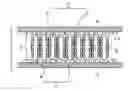
FIG. 1 is a sectional plan view of a linear motor according to a first embodiment of the present invention;
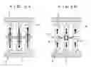
FIG. 2A is a sectional plan view illustrating the path of magnetic flux in the linear motor of FIG. 1;
FIG. 2B is a sectional plan view illustrating the path of magnetic flux in a linear motor of a comparative example;
FIG. 3A is a sectional plan view of a linear motor according to a second embodiment of the present invention, which schematically illustrates the path of magnetic flux when magnetic bolts are used as fastening members for integrally connecting armature core blocks to an armature attachment plate;
FIG. 3B is a sectional plan view of a linear motor according to a second embodiment of the present invention, which schematically illustrates the path of magnetic flux when non-magnetic bolts are used as fastening members for integrally connecting the armature core blocks to the armature attachment plate; and
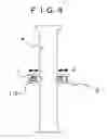
FIG. 4 is a sectional plan view of an armature core block according to a third embodiment of the present invention.
DETAILED DESCRIPTION OF THE EMBODIMENTS
Hereinafter, embodiments of the present invention will be described with reference to the drawings.
First Embodiment
FIG. 1 is a sectional plan view of a linear motor 1 according to a first embodiment of the present invention.
Referring to FIG. 1, the linear motor 1 includes an armature 2 and a field magnet 3 that faces the armature 2 with a gap therebetween. The armature 2 includes a plurality of armature blocks 6 that are connected to each other in a direction in which the armature 2 moves. Each armature block 6 includes an armature core block 4 that is substantially I-shaped and armature coils 5 that are wound around teeth provided in two end portions of the armature core block 4 in the longitudinal direction of the armature core block 4. The field magnet 3 includes a field magnet yoke 7 and a plurality of permanent magnets 8 that are arranged on the field magnet yoke 7 at a regular pitch in such a manner that adjacent permanent magnets 8 have alternate polarities. The permanent magnets 8 that face each other with an armature therebetween have different polarities, so that a through-flux structure, in which magnetic flux from the permanent magnet 8 passes straightly through the armature core block 4, is provided. A step portion 10 is provided at the center of each armature core block 4 so as to extend in a direction perpendicular to the longitudinal direction of the armature core block 4. The step portion 10 has a width larger than that of the teeth portions, and two attachment holes 9 are formed in the side portions thereof.
Next, the principle behind improvement of thrust of a linear motor will be described.
FIG. 2A is a sectional plan view illustrating the path of magnetic flux in the linear motor in FIG. 1, and FIG. 2B is a sectional plan view illustrating the path of magnetic flux in a linear motor of a comparative example.
As illustrated in FIG. 2B, in a linear motor of the comparative example, if the thickness (dimension in the longitudinal direction of the armature core block) of the step portion 10, which is provided at the center of the armature core block 4, is reduced so as to increase the cross-sectional areas of slots, the width of the path of magnetic flux in an attachment hole periphery 91 of the armature core block is reduced and hence the magnetic resistance increases. Therefore, main magnetic flux Φ decreases, and magnetic loading is reduced. Moreover, because the attachment hole is formed at the center of the armature core block, magnetic flux leaks to adjacent armature core blocks, and thrust decreases due to leakage flux Φ1. On the other hand, as illustrated in FIG. 2A, large magnetic flux can pass through the linear motor of the first embodiment, because the attachment hole is not formed at the center of the armature core block and hence the path of magnetic flux has a large width.
Thus, the thickness of the step portion 10 can be reduced without reducing the magnetic loading, so that the cross-sectional areas of coil slots can be increased and electric loading can be improved. Because the attachment holes 9 are formed in the step portion 10, leakage flux between adjacent armature core blocks is interrupted, so that reduction in thrust can be prevented.
When the thickness of the step portion is reduced in order to increase the cross-sectional areas of coil slots, it is necessary that a bolt used as a fastening member have a small diameter. Nevertheless, the strength is secured because each armature core block is fixed to an armature attachment plate at two positions.
Second Embodiment
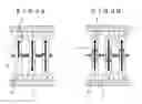
FIG. 3A is a sectional plan view of a linear motor according to a second embodiment of the present invention, which schematically illustrates the path of magnetic flux when magnetic bolts are used as fastening members for integrally connecting the armature core blocks to the armature attachment plate. FIG. 3B is a sectional plan view of a linear motor according to a second embodiment of the present invention, which schematically illustrates the path of magnetic flux when non-magnetic bolts are used as fastening members for integrally connecting the armature core blocks to the armature attachment plate.
As illustrated in FIG. 3A, when magnetic bolts 111 are used, leakage flux is generated and thrust decreases. As illustrated in FIG. 3B, when non-magnetic bolts 112 are used, generation of leakage flux is prevented and reduction in thrust is prevented.
Third Embodiment
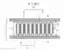
FIG. 4 is a sectional plan view of an armature core block according to a third embodiment of the present invention.
The third embodiment illustrated in FIG. 4 is different from the first and second embodiments in that the attachment holes 9 formed in the step portion 10 of the armature core block 4 have an oblong shape.
With such a structure, when fastening the armature core block 4 to the armature attachment plate, the armature core block 4 can be moved in a direction perpendicular to the longitudinal direction of the armature core block 4 (indicated by an arrow A in FIG. 4), so that the attachment position of the armature core block 4 can be flexibly adjusted. As a result, cogging thrust can be reduced by optimally positioning the armature core block with respect to the armature attachment plate.
In the linear motor of the comparative example, the armature core block is fixed to the armature attachment plate using only one bolt disposed at the center of the armature core block. Therefore, when attaching the armature core block to the armature attachment plate, the armature core block may rotate around the center of the core, so that the distances between adjacent armature core blocks may become irregular and hence cogging thrust may be generated. In contrast, in the linear motor according to the third embodiment, the armature core block is fixed at two positions in the step portion, so that the armature core block does not rotate around the center of the core, whereby the attachment position can be accurately fixed and generation of cogging thrust due to variation in production can be reduced.
As heretofore described, in the first to third embodiments, the attachment hole in the linear motor armature is formed in the armature core block at positions different from the center of the armature core block so as not to interrupt the path of magnetic flux. Therefore, magnetic flux straightly passes through the armature core block along a wide path, whereby a large amount of magnetic flux can pass through the armature core block. As a result, the thrust and torque of the linear motor are increased by using the linear motor armature, and the linear motor can be used for a wide range of motors. The embodiments have a great effect when applied not only to an armature core block made of non-oriented electromagnetic steel sheets but also to an armature core block made of oriented electromagnetic steel sheets.
Claims
What is claimed is:1. A linear motor armature comprising:
a plurality of armature core blocks that are linearly connected to each other, each armature core block being formed of a stack of a plurality of armature cores that are substantially I-shaped, each armature core block including teeth portions around which armature coils are wound, the teeth portions being provided in two end portions of the armature core block in a longitudinal direction of the armature core block, and a step portion extending in a direction perpendicular to the longitudinal direction of the armature core block, the step portion being provided at a center of the armature core block and having a width larger than a width of the teeth portions,
wherein an attachment hole for fixing each of the plurality of armature core blocks to an external armature attachment plate is formed in each of two side portions of the step portion.
2. The linear motor armature according to claim 1,
wherein fastening members are inserted into the attachment holes in the armature core blocks, and the armature core blocks and the armature attachment plate are integrally connected to each other.
3. The linear motor armature according to claim 2,
wherein non-magnetic bolts are used as the fastening members.
4. The linear motor armature according to claim 2,
wherein the attachment holes have an oblong shape, and the armature core blocks and the armature attachment plate are integrally connected to each other with the fastening members.
5. A linear motor comprising:
an armature including a plurality of armature core blocks that are linearly connected to each other, each armature core block being formed of a stack of a plurality of armature cores that are substantially I-shaped, each armature core block including teeth portions around which armature coils are wound, the teeth portions being provided in two end portions of the armature core block in a longitudinal direction of the armature core block, and a step portion extending in a direction perpendicular to the longitudinal direction of the armature core block, the step portion being provided at a center of the armature core block and having a width larger than a width of the teeth portions, wherein an attachment hole for fixing each of the plurality of armature core blocks to an external armature attachment plate is formed in each of two side portions of the step portion; and
a field magnet disposed so as to face the armature with a magnetic gap therebetween, the field magnet including a plurality of permanent magnets arranged adjacent to each other on a field magnet yoke, the plurality of permanent magnets having alternate polarities,
wherein one of the armature and the field magnet serves as a stator and the other of the armature and the field magnet serves a mover that is movable with respect to the stator.
Images & Drawings included:
Sources:
- United States Patent and Trademark Office - verify current appl. status at the USPTO↗
Similar patent applications:
- » 20120049658
Linear motor armature and linear motor - » 20090289509
Cylindrical linear motor armature, cylindrical linear motor field pole, and cylindrical linear motor using them - » 20130033125
LINEAR MOTOR ARMATURE AND LINEAR MOTOR - » 20070040453
Linear motor armature and linear motor using the same - » 20050140213
Linear motor armature and linear motor - » 10496985
Linear motor armature and linear motor - » 20080265691
Canned linear motor armature and canned linear motor - » 20090015076
Canned linear motor armature and canned linear motor - » 20070252444
Canned linear motor armature and canned linear motor - » 20090315414
Canned linear motor armature and canned linear motor
Recent applications in this class:
- » 20250125702 2025-04-17
DIRECT DRIVE TRANSMISSION SYSTEM - » 20250119044 2025-04-10
DIRECT-DRIVE SYSTEM - » 20250070633 2025-02-27
TOPOLOGIES TO REDUCE FORCE RIPPLE FOR PROPULSION MOTORS - » 20250070632 2025-02-27
PROPULSION MOTOR TOPOLOGIES - » 20240297560 2024-09-05
DRIVING MECHANISM - » 20240266935 2024-08-08
Adjustable System to Minimize Magnetic Motor Side Loads - » 20240258896 2024-08-01
Dual Pumping Hydrofoil System And Balanced Dual Linear Drive Propulsion System And Vehicles And Boats Using Same - » 20240106312 2024-03-28
CURVILINEAR TRACK SECTIONS HAVING POSITION SENSORS - » 20230155469 2023-05-18
Multi-axis linear motor actuator - » 20230040955 2023-02-09
Transfer apparatus and transfer method
Recent applications for this Assignee:
- » 20250242493 2025-07-31
DETERMINATION OF CONSTRAINT FOR ROBOT CONTROL - » 20250205890 2025-06-26
DETERMINATION OF HOLDING POSITION ON WORKPIECE - » 20250205889 2025-06-26
DETERMINATION OF POSITIONAL RELATIONSHIP BETWEEN WORKPIECE AND ROBOT - » 20250170729 2025-05-29
ROBOT - » 20250170728 2025-05-29
ROBOT - » 20250170704 2025-05-29
ROBOT - » 20250162137 2025-05-22
ROBOT AND METHOD FOR MANUFACTURING ROBOT - » 20250162136 2025-05-22
ROBOT AND METHOD FOR MANUFACTURING ROBOT - » 20250144813 2025-05-08
ROBOT SYSTEM, ROBOT, AND ROBOT CONTROL METHOD - » 20250133689 2025-04-24
CONTROL APPARATUS AND COOLING METHOD OF CONTROL APPARATUS