Two stroke engine with regular lubrication system
US20100326411A1
2010-12-30
12/495,764
2009-06-30
✅ Patent granted
US 8,371,255 B2
2013-02-12
-
-
Noah Kamen
2031-08-21
Abstract:
This is a novel two-stroke engine design which achieves the best properties of both the two and the four-stroke types of engine. The design has a simple and effective lubrication system, a clean exhaust system, and an increased power to displacement ratio.
Applicant:
Interested in similar patents?
Get notified when new applications in this technology area are published.
Classification:
F02B33/40 » CPC main
Engines characterised by provision of pumps for charging or scavenging; Engines with pumps other than of reciprocating-piston type with rotary pumps of non-positive-displacement type
F01N5/04 » CPC further
Exhaust or silencing apparatus combined or associated with devices profiting from exhaust energy the devices using kinetic energy
F02B25/04 » CPC further
Engines characterised by using fresh charge for scavenging cylinders using unidirectional scavenging Engines having ports both in cylinder head and in cylinder wall near bottom of piston stroke
F02B39/10 » CPC further
Component parts, details, or accessories relating to, driven charging or scavenging pumps, not provided for in groups - ; Drives of pumps ; Varying pump drive gear ratio; Non-mechanical drives, e.g. fluid drives having variable gear ratio electric
F02B77/085 » CPC further
Component parts, details or accessories, not otherwise provided for; Safety, indicating or supervising devices with sensors measuring combustion processes, e.g. knocking, pressure, ionization, combustion flame
Y02T10/12 » CPC further
Road transport of goods or passengers; Internal combustion engine [ICE] based vehicles Improving ICE efficiencies
Y02T10/12 » CPC further
Road transport of goods or passengers; Internal combustion engine [ICE] based vehicles Improving ICE efficiencies
F02B33/44 » CPC further
Engines characterised by provision of pumps for charging or scavenging Passages conducting the charge from the pump to the engine inlet, e.g. reservoirs
F02B33/00 IPC
Engines characterised by provision of driven charging or scavenging pumps
F02B33/00 IPC
Engines characterised by provision of pumps for charging or scavenging
F02B25/00 IPC
Engines characterised by provision for charging or scavenging
F02B25/00 IPC
Engines characterised by using fresh charge for scavenging cylinders
Description
BRIEF SUMMARY OF INVENTION
This is a new design for two stroke engines that incorporates advantages of both the two-stroke and four-stroke types of engines. The engine is lubricated exactly like a four-stroke engine; it has piston rings that lubricate the piston and the cylinder, i.e. the oil control ring, as well as all the customary lubricating parts such as the oil pan with the oil pump and the oil distribution system. The engine uses two camshafts, one for the intake valve and the other for the exhaust valve. The engine has a compressor, powered by the engine battery to compress ambient air before it enters into the combustion chamber. Additionally, the engine has an exhaust powered turbine connected to an alternator, which provides additional power for the engine battery. The engine is equipped with one or plurality of fuel-injection nozzles. The piston is of the two step type, which reduces friction between the piston and the cylinder. The operation of the engine is controlled by a computer, the Engine Control Unit (ECU).
BRIEF DESCRIPTION OF SEVERAL VIEWS OF THE DRAWING
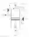
FIG. 1, FIG. 2, FIG. 3, and FIG. 4 are cutaway views of the engine design; they all have the same elements, numbered the same, with the only difference being in the position of the moving parts. Therefore, element descriptions are the same for FIG. 1, FIG. 2, FIG. 3 and FIG. 4, which are as follows:
| Element Number | Description |
| ~1 | Injector connected to ~80 (ECU) |
| ~72 | Ambient air inlet |
| ~71 | Compressor |
| ~73 | Compressed air chamber |
| ~74 | Compressed air pipe |
| ~77 | Electric motor connected to ~80 (ECU) |
| ~80 | Engine Control Unit (ECU) |
| ~81 | Pressure sensor connected to element ~80 |
| (ECU) | |
| ~46 | Intake valve |
| ~41 | Intake camshaft |
| ~45 | Intake cam |
| ~40 | Piston |
| ~82 | rpm sensor |
| ~60 | Exhaust turbine |
| ~61 | Alternator connected to element ~80 (ECU) |
| ~56 | Exhaust valve |
| ~55 | Exhaust cam |
| ~51 | Exhaust camshaft |
| ~10 | Cylinder body |
| ~12 | Compression area |
FIG. 5 is a cutaway view of the piston which fits inside the cylinder (FIG. 1 ˜10). Element ˜42 is the lower part of the piston and consists of three rings shown as elements ˜43 and ˜44. Element ˜41 is the upper part of the piston.
DETAILED DESCRIPTION OF THE INVENTION
The cycle begins when the ignition key is turned to the start position and the electric motor (FIG. 1. ˜77) starts to drive the compressor (FIG. 1. ˜71) which drives the fresh ambient air into the compressed air chamber (FIG. 1. ˜73). The pressure sensor (FIG. 1. ˜81) delivers the information to the ECU (FIG. 1. ˜80) which, when the pressure in the compressed air chamber (FIG. 1. ˜73) reaches a certain defined amount, turns the engine over, thereby starting the operation of the engine. Initially, the start phase lasts a few seconds, but in subsequent engine starts, that phase is shorter as there is already some pressure in the compressed air chamber (FIG. 1. ˜73). Compressed ambient air enters the cylinder (engine is turning), in the top piston position the intake and the exhaust valves are closed and the pressure necessary for ignition is achieved. The injector (FIG. 1. ˜1) injects the fuel into the compression area (FIG. 1. ˜12) and the air-fuel mixture is ignited. Pressure pushes the piston (FIG. 1. ˜40) down. Just before the piston reaches the bottom position, the exhaust valve (FIG. 2. ˜56) is opened, exhaust gases leave the cylinder driving the exhaust turbine (FIG. 2. ˜60), which in turn drives the alternator (FIG. 2. ˜61) that charges the battery, which, in turn, is mostly used to run the electric motor (FIG. 2. ˜77) and the compressor (FIG. 2. ˜71). A moment later, but still before the bottom piston position, the intake valve (FIG. 3. ˜46) is opened. Ambient air enters the cylinder but exhaust valve vent (FIG. 3. ˜56) is still opened for a brief moment so that last remaining exhaust combusted mix is pushed out with some of the fresh ambient air. Exhaust valve vent (FIG. 3. ˜56) closes at the bottom position of the piston and as the piston moves up the intake valve (FIG. 4. ˜46) closes as well, allowing the piston to compress the fresh ambient air into the compression area (FIG. 4. ˜12). This cycle repeats indefinitely while engine operates. The ECU continuously monitors the rpm through an rpm sensor (FIG. 4. ˜82), pressure in the air compression chamber (FIG. 4. ˜73) through a pressure sensor (FIG. 4. ˜81), and the charge level in the battery thereby creating optimal conditions for engine operation.
The piston has a unique form: the lower part has rings (FIG. 5. ˜42) that lubricate and seal the piston to the cylinder, while the upper part above the rings (FIG. 5. ˜41) is slightly narrower than the cylinder, and it that upper part it never touches the cylinder walls. The size of the volume of the upper part is intended to provide for enough pressure in the combustion chamber. The wrist pin could be placed in the upper part of the piston (FIG. 5. ˜42), which would allow for a shorter engine.
There is an alternative, cheaper variant, which like a traditional two-stroke engine brings air into the crankcase. The advantage of this variant is that it would not need a compressed air chamber (FIG. 1 ˜73), and the compressor (FIG. 1 ˜71) and the exhaust turbine (FIG. 1 ˜60) would be smaller and cheaper. The disadvantages are that a more expensive form of lubrication, such as dry-sump, would be necessary, and that the overall engine operation would be less efficient, leading to higher operating costs.
The traditional lubrication system used in four-stroke engines has proven to be the most effective solution to the problem of lubricating the moving, mechanical-power generating parts of an internal combustion engine. Until now this system was not available for two-stroke engines. The proposed engine combines the best features of both the two and the four-stroke types of engines: lubrication system is simple and effective as in the four-stroke, the exhaust is clean as in the four-stroke, and for the same displacement the proposed engine would have more than twice the power.
The proposed engine is described above in its diesel version, but with minor modifications it can be made into a gasoline one. The gasoline version would use a direct fuel-injection system (NO carbureted version is possible), and would have a smaller compression ratio.
Claims
1. The proposed two-stroke engine design achieves the best properties of both the two and the four-stroke types of engines because of the following characteristics:
1) the lubrication system is simple and effective,
2) the exhaust is cleaner than traditional two-stroke,
3) for the same displacement as the four-stroke it has more than twice the power, and
4) decoupling of the compressor (FIG. 1, ˜71) and the exhaust turbine (FIG. 1, ˜60) allows for more efficient operation and more effective control by the ECU (FIG. 1, ˜80) (for example, if the ECU (FIG. 1, ˜80) detects a need for a burst of power, the compressor (FIG. 1, ˜71) can be commanded to operate for a longer period of time and/or at a faster rate independently of the exhaust turbine (FIG. 1, ˜60) to produce the needed effect).
Images & Drawings included:


Sources:
- United States Patent and Trademark Office - verify current appl. status at the USPTO↗
Recent applications in this class:
- » 20230212976 2023-07-06
SUPERCHARGER - » 20230160335 2023-05-25
Utility vehicle - » 20220243646 2022-08-04
CHARGED SERIAL HYBRID COMBUSTION ENGINE - » 20220195912 2022-06-23
Turbocharger and turbine wheel for a turbine of a turbocharger - » 20220074342 2022-03-10
SUPERCHARGER WITH TWO COMPRESSORS DRIVEN TOGETHER ON A SINGLE SHAFT - » 20210324788 2021-10-21
Turbocharger having a thermal dam - » 20210071566 2021-03-11
Apparatus and method for increasing air flow and air velocity entering the air intake of an internal combustion engine - » 20210062711 2021-03-04
Reciprocating engine system with electrically driven compressor and method for operating same - » 20200271045 2020-08-27
Centrifugal compressor and turbocharger - » 20200224584 2020-07-16
SUPERCHARGER