RANGE HOOD
US20100326419A1
2010-12-30
12/874,236
2010-09-02
Abstract:
A range hood, containing at least a fan having a housing and an impeller, an oil filter, a cover, a fume exhaust cover, a light, and a switch. The housing of the fan is a circular double-chamber or multi-chamber structure with an air inlet and an air outlet, and the impeller of the fan contains at least one group of arc-shaped blades each having a closed side and being enlarged in an axial direction.
Assignee:
- SHANDONG UNIVERSITY 210 🇨🇳 Jinan, China
Interested in similar patents?
Get notified when new applications in this technology area are published.
Description
CROSS-REFERENCE TO RELATED APPLICATIONS
This application is a continuation of International Patent Application No. PCT/CN2009/000516 with an international filing date of May 13, 2009, designating the United States, now pending, and further claims priority benefits to Chinese Patent Application No. 200810017064.7 filed on Jun. 25, 2008, and to Chinese Patent Application No. 200820024568.7 filed on Jun. 25, 2008. The contents of all of the aforementioned applications, including any intervening amendments thereto, are incorporated herein by reference.
BACKGROUND OF THE INVENTION
1. Field of the Invention
The invention relates to a range hood.
2. Description of the Related Art
Range hoods are widely used nowadays. However, there are several problems with the conventional range hoods: first, large amount of oil remains on fans thereof after long-time use, which affects oil suction and brings about large noise; second, they are low-efficient and power consuming; and third, their operation contaminates indoor and outdoor environment; and finally, cleaning thereof cost users a lot.
SUMMARY OF THE INVENTION
In view of the above-described problems, it is one objective of the invention to provide a range hood that is capable of addressing the above-mentioned problems.
To achieve the above objectives, in accordance with one embodiment of the invention, provided is a range hood, comprising a fan having a housing and an impeller, an oil filter, a cover, a fume exhaust cover, a light, and a switch. The housing of the fan is a circular double-chamber or multi-chamber structure with an air inlet and an air outlet, and the impeller of the fan comprises at least one group of arc-shaped blades each having a closed side and being enlarged in an axial direction.
In a class of this embodiment, the housing of the fan comprises a swirl chamber and an impeller chamber.
In a class of this embodiment, the impeller is disposed in the impeller chamber.
In a class of this embodiment, a motor is disposed at the top of the housing.
In a class of this embodiment, the impeller is connected to the motor.
In a class of this embodiment, the air inlet is disposed at the bottom of the swirl chamber, and the air outlet is disposed on the right of the swirl chamber.
In a class of this embodiment, a blade of the impeller is disposed on an impeller disk, and the impeller disk is connected to a motor shaft of the motor, and a seal sheet is disposed in the front of the impeller disk.
In a class of this embodiment, the oil filter comprises a support, a first oil screen, a second oil screen, and an oil tray.
In a class of this embodiment, the first oil screen is fit on the support, the second oil screen is disposed at the top of the support, and the oil tray is connected to the bottom of the support.
In a class of this embodiment, the first oil screen and the second oil screen are made of soft materials, and the oil tray is made of hard materials such as plastics or metal plates.
In a class of this embodiment, the oil filter is in the shape of a frustum.
In a class of this embodiment, three sides of the fume exhaust cover are closed.
In a class of this embodiment, the fume exhaust cover comprises a metal frame, a metal plate, and a glass plate, the metal plate operates to seal a lower part of the metal frame, and the glass plate operates to seal an upper part of the metal frame.
Advantages of the invention comprise:
1. the impeller, the blade, and the housing cause gas not to be collided with the impeller or the housing, oil smoke does not pass the impeller, and thus volume loss, flow loss and power consumption are significantly reduced, and work life of the impeller is increased; on the other hand, the arc-shaped blade having a closed side is disposed in the double-chamber structure of the housing and forms a swirling flow field that quickly rotates with respect to the shaft whereby reinforcing convergence. The swirling flow field transmits gas in a manner of “driving gas via gas” instead of using a rotating impeller or a blade, and thus a new power transmission mode—a swirling flow field mode is formed. Oil is not attached to the range hood, which ensures cleaning of the impeller without disassembling, and the invention features high efficiency, low power consumption and noise, few consumables, easy production, and long work life.
2. by using the frustum-shaped oil filter, oil smoke is filtered for two times via the first oil screen and the second oil screen, and thus complete separation between oil and smoke is implemented, which significantly improves purification rate of oil and smoke, ensures cleaning in the range hood, and prevents outdoor environment pollution. The first oil screen and the second oil screen are made of soft materials that are convenient to be cleaned or replaced, which reduces maintenance cost.
3. the fume exhaust cover having three closed sides can completely cover the oil smoke and prevent it from dissipating, which improves suction efficiency, and ensures freshness of indoor air and cleaning of walls.
4. compared with the conventional range hood, the invention increases suction efficiency by above 10% and reduces power consumption by above 10%, noise thereof is ≦50 dB, suction rate of oil smoke is above 95%, purification rate of oil smoke is above 90%, and a work life thereof is three times longer than the conventional range hood. To summarize, the invention features high efficient, low power consumption and no attached oil, is cleaning and environment-friendly, and is convenient for cleaning. Technical and economic index of the invention reach the top level in the world, energy saving and emission reduction effect caused thereby is significant, and economic and social benefit is remarkable.
5. Principle and a technique of the invention can be widely applicable for production of range hoods in family kitchens, hotels, restaurants, cafeterias, and so on.
BRIEF DESCRIPTION OF THE DRAWINGS
FIG. 1 is a schematic view of a range hood of an exemplary embodiment of the invention;
FIG. 2 is a schematic view of a fan;
FIG. 3 is a schematic view of an impeller;
FIG. 4 is a schematic view of an oil filter;
FIG. 5 is a front view of a fume exhaust cover; and
FIG. 6 is a side view of a fume exhaust cover.
In which:
1—fan; 2—oil filter; 3—cover; 4—fume exhaust cover; 5—switch; 6—impeller; 7—motor; 8—air outlet; 9—impeller chamber; 10—air inlet; 11—swirl chamber; 12—housing; 13—blade; 14—impeller disk; 15—seal sheet; 16—second oil screen; 17—first oil screen; 18—support; 19—oil tray; 20—metal frame; 21—glass plate; 22—metal plate
DETAILED DESCRIPTION OF THE EMBODIMENTS
Further description will be given below in conjunction with accompanying drawings.
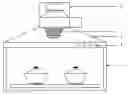
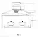
As shown in FIG. 1, a range hood of the invention comprises a fan 1, an oil filter 2, a cover 3, a fume exhaust cover 4, a light, and a switch 5.
As shown in FIGS. 1—3, the fan 1 comprises a housing 12, an impeller 6, a swirl chamber 11, an impeller chamber 9, an air inlet 10, an air outlet 8, and a motor 7.
The impeller 6 of the fan 1 comprises at least one group of arc-shaped blades 13 each having a closed side and being enlarged in an axial direction.
The housing 12 of the fan 1 is a circular double-chamber or multi-chamber structure with the air inlet 10 and the air outlet 8. The housing 12 comprises a swirl chamber 11 and an impeller chamber 9.
The impeller 6 is disposed in the wheel chamber 9 and connected to the motor 7 disposed at the top of the housing 12.
The air inlet 10 is disposed at the bottom of the swirl chamber 11, and the air outlet 8 is disposed on the right of the swirl chamber 11.
As shown in FIG. 3, the impeller 6 comprises the blade 13 and an impeller disk 14 connected to each other. The impeller disk 14 is connected to a motor shaft of the motor 7. A seal sheet 15 is disposed in the front of the impeller disk 14.
As shown in FIG. 4, the oil filter 2 is in the shape of a frustum, and comprises a support 18, a first oil screen 17, a second oil screen 16, and an oil tray 19.
The first oil screen 17 is fit on the support 18, the second oil screen 16 is disposed at the top of the support 18, and the oil tray 19 is connected to the bottom of the support 18.
The first oil screen 17 is made of soft materials such as nylon screens, the second oil screen 16 is made of soft materials such as multi-layer gauzes, and the oil tray 19 is made of hard materials such as plastics or metal plates.
As shown in FIGS. 5 and 6, three sides of the fume exhaust cover 4 are closed. The fume exhaust cover 4 comprises a metal frame 20, a metal plate 22, and a glass plate 21, the metal plate 22 operates to seal a lower part of the metal frame 20, and the glass plate 21 operates to seal an upper part of the metal frame 20.
While particular embodiments of the invention have been shown and described, it will be obvious to those skilled in the art that changes and modifications may be made without departing from the invention in its broader aspects, and therefore, the aim in the appended claims is to cover all such changes and modifications as fall within the true spirit and scope of the invention.
Claims
The invention claimed is:1. A range hood, comprising
a fan (1) having a housing (12) and an impeller (6);
an oil filter (2);
a cover (3);
a fume exhaust cover (4);
a light; and
a switch (5);
wherein
said housing (12) of said fan (1) is a circular double-chamber or multi-chamber structure with an air inlet (10) and an air outlet (8); and
said impeller (6) of said fan (1) comprises at least one group of arc-shaped blades (13) each having a closed side and being enlarged in an axial direction.
2. The range hood of claim 1, wherein said housing (12) of said fan (1) comprises a swirl chamber (11) and an impeller chamber (9).
3. The range hood of claim 2, wherein said impeller (6) is disposed in said impeller chamber (9).
4. The range hood of claim 3, wherein a motor (7) is disposed at the top of said housing (12).
5. The range hood of claim 4, wherein said impeller (6) is connected to said motor (7).
6. The range hood of claim 5, wherein said air inlet (10) is disposed at the bottom of said swirl chamber (11), and said air outlet (8) is disposed on the right of said swirl chamber (11).
7. The range hood of claim 4, wherein
a blade (13) of said impeller (6) is disposed on an impeller disk (14);
said impeller disk (14) is connected to a motor shaft of said motor (7); and
a seal sheet (15) is disposed in the front of said impeller disk (14).
8. The range hood of claim 1, wherein said oil filter (2) comprises a support (18), a first oil screen (17), a second oil screen (16), and an oil tray (19).
9. The range hood of claim 8, wherein
said first oil screen (17) is fit on said support (18);
said second oil screen (16) is disposed at the top of said support (18); and
said oil tray (19) is connected to the bottom of said support (18).
10. The range hood of claim 8, wherein
said first oil screen (17) and said second oil screen (16) are made of soft materials; and
said oil tray (19) is made of hard materials such as plastics or metal plates.
11. The range hood of claim 8, wherein said oil filter (2) is in the shape of a frustum.
12. The range hood of claim 1, wherein three sides of said fume exhaust cover (4) are closed.
13. The range hood of claim 12, wherein
said fume exhaust cover (4) comprises a metal frame (20), a metal plate (22), and a glass plate (21);
said metal plate (22) operates to seal a lower part of said metal frame (20); and
said glass plate (21) operates to seal an upper part of said metal frame (20).
Images & Drawings included:


Sources:
- United States Patent and Trademark Office - verify current appl. status at the USPTO↗
Similar patent applications:
- » 20200232649
Fume collecting assembly, range hood, side suction range hood, range hood for two-sided fume collection and central air intake, range hood with partition, and central fume purification device - » 20220221160
CONTROL METHOD FOR RANGE HOOD AND RANGE HOOD - » 20190368748
Lifting mechanism with movable component and for range hood, and range hood using lifting mechanism - » 20180372332
RANGE HOOD AND METHOD FOR CONTROLLING THE RANGE HOOD - » 20220221161
Range hood and method for controlling the range hood - » 20190316784
HOUSEHOLD RANGE HOOD SYSTEM AND METHOD OF CONTROLLING A HOUSEHOLD RANGE HOOD - » 20060070617
Range hood fan having filter - » 20060042622
Wall-mounted range hood - » 20050051159
Range hood - » 20060249141
Range hood with overlay panels
Recent applications in this class:
- » 20250155131 2025-05-15
RANGE HOODS AND VEHICLES - » 20250003599 2025-01-02
AIR FRYING SYSTEM FOR GAS OVEN COOKING APPLIANCE - » 20240426485 2024-12-26
COOKER HOOD - » 20240361005 2024-10-31
VENTILATION HOOD AND PROCESS FOR MAKING SAME - » 20240344712 2024-10-17
DEPLOYABLE KITCHEN WITH AN EXHAUST ASSEMBLY - » 20240044511 2024-02-08
METHOD FOR MONITORING A COOKING PROCESS, AND CONTROL DEVICE - » 20230417422 2023-12-28
EXTRACTION DEVICE AND METHOD FOR OPERATING THE SAME - » 20230417421 2023-12-28
IMPROVED FAN ASSEMBLY FOR EXTRACTOR HOOD FOR HOBS - » 20230280043 2023-09-07
Range hood and method for controlling the same - » 20230235892 2023-07-27
Range hood for preventing air pollution
Recent applications for this Assignee:
- » 20250175216 2025-05-29
DIGITAL TWIN-BASED DEDUCTION AND OPTIMIZATION METHOD AND SYSTEM FOR INTELLIGENT REFLECTING SURFACE COMMUNICATION SYSTEM - » 20250165809 2025-05-22
PRIVACY-PRESERVING TASK-ORIENTED SEMANTIC COMMUNICATION METHOD AND SYSTEM - » 20250155589 2025-05-15
Structure for slow neutron detection and method for slow neutron energy spectrum measurement - » 20250137476 2025-05-01
HYDRAULIC SYSTEM, METHOD, AND INTEGRATED VALVE BLOCK OF SLEWING MECHANISM - » 20250118068 2025-04-10
METHOD AND SYSTEM FOR DETECTING CHANGES IN AREAS - » 20250079848 2025-03-06
METHOD FOR MANAGING HEAT-ELECTRIC OUTPUTS OF HIGH-PROPORTION NEW ENERGY SYSTEM BASED ON CSP-CHP COMBINED ENERGY SUPPLY AND SYSTEM THEREOF - » 20250022158 2025-01-16
OPTIMIZED METHOD FOR IDENTIFICATING ROBOT POURING REGIONS BASED ON HIERARCHICAL PROCESSING AND CONNECTIVITY MAXIMIZATION AND SYSTEM THEREOF - » 20250019247 2025-01-16
TWO-DIMENSIONAL POROUS SILICON, AND PREPARATION METHOD AND USE THEREOF IN LITHIUM ION BATTERIES - » 20250012868 2025-01-09
METHOD FOR STANDARDIZING DECOMMISSIONING DEFINITION OF POWER BATTERIES AND SYSTEM THEREOF - » 20240426891 2024-12-26
HIGH-IMPEDANCE FAULT POSITIONING METHOD AND SYSTEM BASED ON SYNCHRONOUS LISSAJOUS CURVE CHARACTERISTICS