Spool for winding metallic wire
US20100327103A1
2010-12-30
12/867,557
2009-02-05
✅ Patent granted
US 8,418,951 B2
2013-04-16
WO; PCT/EP2009/051300; 20090205
WO; WO2009/101019; 20090820
William E Dondero
Scully, Scott, Murphy & Presser, P.C.
2029-10-13
Abstract:
A spool for winding metallic wire, comprising a tubular body for supporting the coil of wire that is provided, at ends thereof, with wall elements, each wall element comprising a flat flange with a stiffening fold at the outer edge, jointly connected by welding to the corresponding end of the tubular body, and a flat complementary flange, seamed by spot welding to the outer surface of the flange, at least one pawl being jointly connected to the complementary flange of at least one wall element.
Assignee:
- SODETAL SAS 1 🇫🇷 Tronville-en-Barrois, France
Applicant:
Interested in similar patents?
Get notified when new applications in this technology area are published.
Classification:
B65H2701/5114 » CPC further
Handled material; Storage means; Storage means for webs, tapes, or filamentary material; Cores or reels characterised by the material essentially made of sheet material Metal sheets
B65H75/18 IPC
Storing webs, tapes, or filamentary material, e.g. on reels; Cores, formers, supports, or holders for coiled, wound, or folded material, e.g. reels, spindles, bobbins, cop tubes, cans, mandrels or chucks Constructional details
B65H75/30 » CPC further
Storing webs, tapes, or filamentary material, e.g. on reels; Cores, formers, supports, or holders for coiled, wound, or folded material, e.g. reels, spindles, bobbins, cop tubes, cans, mandrels or chucks; Constructional details Arrangements to facilitate driving or braking
B65H75/14 » CPC main
Storing webs, tapes, or filamentary material, e.g. on reels; Cores, formers, supports, or holders for coiled, wound, or folded material, e.g. reels, spindles, bobbins, cop tubes, cans, mandrels or chucks; Kinds or types of circular or polygonal cross-section with two end flanges
Description
TECHNICAL FIELD
The present invention relates to a spool for winding metallic wire.
BACKGROUND ART
It is known that spools for winding metallic wire, which comprise a tubular body for supporting the coil of wire that is provided, at its ends, with wall elements for containing the coil, are widely used in the industrial field.
Known spools suffer some drawbacks.
DISCLOSURE OF THE INVENTION
Therefore the aim of the present invention is to provide a spool that has maximum constructive simplicity and considerable stiffening characteristics.
This aim, this and other objects which will become better apparent hereinafter, are achieved by a spool for winding metallic wire, according to the present invention, comprising a tubular body for supporting a coil of wire that is provided, at ends thereof, with wall elements for containing said coil, at least one of which is provided, at a surface directed outward, with at least one pawl for engagement with means for turning said spool, characterized in that each wall element comprises a flat flange with a stiffening fold out at the outer edge, which is jointly connected by welding to the corresponding end of the tubular body, and a flat complementary flange, which is seamed by spot welding to the outer surface of said flange, at least one pawl being jointly connected to said complementary flange of at least one wall element.
BRIEF DESCRIPTION OF THE DRAWINGS
Further characteristics and advantages of the spool according to the present invention will become better apparent from the description of a preferred but not exclusive embodiment thereof, illustrated by way of non-limiting example in the accompanying drawings, wherein:
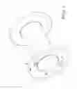
FIG. 1 is a perspective view of the spool, according to the invention;
FIG. 2 is a view of a detail of FIG. 1.
WAYS OF CARRYING OUT THE INVENTION
With reference to the figures, reference numeral 1 designates a tubular body for supporting a coil of wire that is provided, at its ends, with two wall elements 2 and 3, which are mirror-symmetrically identical.
Therefore, only the element 2 is described. It comprises a flat flange 4, with a stiffening fold 4a at the outer edge, jointly connected by welding 4b to the corresponding end of the tubular body 1.
A flat complementary flange 5 is seamed to the flange 4 at the outer surface of the flange by means of spot welds 5a, 5b and is provided with at least one and preferably two jointly connected pawls 6 and 7 which are associated with the complementary flange by welding at an inner edge 6a for the pawl 6; as regards such pawls, it should be noted that they might be is absent in the wall element 3.
The pawls are adapted for engagement with means for turning the spool.
Finally, the two ends of the tubular body 1 have the wall shaped like a bevel 1a for the end that can be seen in FIG. 2; such bevel allows convenient ways of approaching the spindle designed to support the spool during operation.
From what has been described it is readily evident that the spool according to the invention lends itself to be provided according to very simple manufacturing methods, and it is also noted that it has stiffness characteristics that ensure maximum correctness in operation.
In the practical embodiment of the invention, all the details may be replaced with other technically equivalent elements.
The disclosures in Italian Utility Model Application No. MN2008U0000002 from which this application claims priority are incorporated herein by reference.
Claims
1-3. (canceled)
4. A spool for winding metallic wire, comprising a tubular body for supporting a coil of wire that is provided, at ends thereof, with wall elements for containing said coil, at least one of which is provided, at a surface directed outward, with at least one pawl for engagement with means for turning said spool, wherein each wall element comprises a flat flange with a stiffening fold at the outer edge, which is jointly connected by welding to the corresponding end of the tubular body, and a flat complementary flange, which is seamed by spot welding to the outer surface of said flange, at least one pawl being jointly connected to said complementary flange of at least one wall element.
5. The spool according to claim 4, wherein the two ends of the tubular body have the wall shaped so as to form a bevel.
6. The spool according to claim 4, wherein each pawl is jointly connected to the corresponding complementary flange by welding at the inner edge.
Images & Drawings included:


Sources:
- United States Patent and Trademark Office - verify current appl. status at the USPTO↗
Recent applications in this class:
- » 20250178858 2025-06-05
REUSABLE REEL - » 20250066155 2025-02-27
REEL ARRANGEMENT AND LOCKING MECHANISM - » 20240417210 2024-12-19
Induction Bonded Reel Having a Hub Member - » 20240317540 2024-09-26
REEL ASSEMBLIES AND METHODS OF MAKING AND USING REEL ASSEMBLIES - » 20240317539 2024-09-26
Apparatus for removing flexible filament from a spool - » 20240140757 2024-05-02
Rotatable Cable Reel - » 20230406668 2023-12-21
Rotatable Cable Reel - » 20230339720 2023-10-26
REEL MEMBER AND ADHESIVE FILM WINDING BODY - » 20230211976 2023-07-06
REEL FOR WINDING AND UNWINDING A LINK - » 20230166941 2023-06-01
WELDING WIRE SPOOL WITH BREAKAWAY TAB