Road farm unit
US20100327602A1
2010-12-30
12/455,068
2009-06-29
Abstract:
Taking advantage of a provisional patent filed Jan. 21, 2009 confirmation number 8217. 1 hereby claim to be the original inventor of the road farm unit. The units are set In each lane of a road or rail road track. Vehicles or trains passing over said units would spin a wheel connected to a generator thereby creating electric power. Advantages over wind farm units which need wind over 15 mph to produce electric power are much more costly and are usually many miles from a power grid and also kill birds.
Interested in similar patents?
Get notified when new applications in this technology area are published.
Classification:
F03G7/00 » CPC main
Mechanical-power-producing mechanisms, not otherwise provided for or using energy sources not otherwise provided for
Description
BRIEF SUMMARY OF THE INVENTION
The Road Farm Units would produce electricity from moving vehicles or trains as they pass over said units. The units could add to or replace costly Wind Farms and Solar Panels and create a MULTITUDE of jobs, cut down on greenhouse gases and slow down or do away with our dependence of foreign oil. There are 2 types of units one being a Rubber Wheel the other a Turbine Wind Wheel. Both the wheels are encased in the same type of cement box but have different tops. The wheels are connected to a generator or alternator to produce electricity for distribution. The power produced could power building adjacent to a road, traffic and street lights, even stations along a road to charge your electric/hybrid vehicle. Excess power would be sent back to the electric company's power grid.
DETAILED DESCRIPTION OF THE INVENTION
There are two types of Road Farm Units, a rubber wheel type #21 and a wind turbine type #22.
Both units are to be used on roads or highways #19 or railroad tracks #20. The purpose is to produce electricity from a spinning wheel.
The first type is solid rubber wheel #1 with tire type treads #24 in it with a center shaft #3 that goes through a ball bearing hub #2. The hub #2 is supported at each end by a bracket #4. The wheel #1 is set in a pre-cast reinforced cement housing #6 which has an adjusting bolt #5, and the wheel is adjusted so it is slightly above the road #7. There are curve tops #10 with a slight clearance between them and the wheel, and are hinged #11 so wheel #1 and bracket #4 assembly can be removed for replacement or repairs. The units are placed along a road #7 in a irregular pattern and are made just wide enough so one side of a vehicle would only have to pass over to spin wheel #1. The whole unit #21 could be about 3 or 4 feet wide. A dry well #9 could be incorporated for use in a high rainfall area. The unit #21 is fastened to the road by security fasteners #8 through the top flange #12. In a railroad #20 application the units would be placed between the track and the railroad ties#20. A small flexible flapper could be installed under the train to spin the wheel #1. The unit #21 would have to be placed slightly above the railroad ties #20.
The second type of unit #22 is a Wind Turbine Wheel #15 which would be used instead a rubber wheel #1. A different type of top #18 is used to direct the wind from passing vehicles as show by arrow #17, to spin the wheel #15. The turbine wheel would be made of a light weight aluminum or plastic. This type of unit #22 would be placed in a center lane #19 so the center part of a vehicle would pass over it. In a railroad #20 installation, there would be no need for a flapper under the train.
BRIEF DESCRIPTION OF THE SEVERAL VIEWS OF THE DRAWINGS
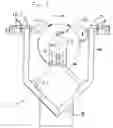
FIG. 1: Side End View—Shows a rubber wheel #1 slightly above the road #7 supported by a bracket #4 encased in a cement box #6 which has an adjusting bolt #5 and a curved top #10 that is hinged for installation and maintenance purposes. In addition an optional dry well #9 for heavy rainfall areas.
FIG. 2: Open Side View—Shows rubber wheel #1 center shaft #3 with a ball bearing hub #2 on each end. A generator or alternator #13 and conduit #14. There are security fasteners #8 for the top flange #12 and curved top #10 along with tire treads #24 on the wheel.
FIG. 3: Top View of Unit—#21 encased in a road #7
FIG. 4: End View—Is the second type of unit #22. The only difference being a wind turbine #15 and a Wind Scoop Top #18 instead of a rubber wheel #1 type.
FIG. 5: Side View—This is a Wind Turbine type #22.
FIG. 6: Top View of Wind Turbine Type—#22
FIG. 7: Top View of a typical two lane road #9 with units #21 in different lanes as not to tie up traffic for installation or repairs.
FIG. 8: Top View of Railroad Track—#20 with units #21 placed between the tracks #20.
FIG. 9: Top View of Typical Two Lane Road—#19 with units #22 in the center of different lanes.
FIG. 10: Top View of Railroad Track—#20 with units #22 between the tracks #20
COMPONENTS FOR DETAILED DESCRIPTION
1. Rubber Wheel
2. Ball Bearing hub
3. Wheel Shaft
4. Hub and Wheel Bracket
5. Adjusting Bolt
6. Cement Housing
7. Road
8. Flange Security Fasteners
9. Dry Well
10. Curved Top For Rubber Wheel
11. Hinge
12. Flange
13. Generator or Alternator
14. Conduit
15. Turbine Wind Wheel
16. Arrow For Traffic Direction
17. Arrow For Wind Direction
18. Wind Scoop Top For Wind Wheel
19. Two Lane Road or Multi Lane Highway
20. Railroad Track
21. Complete Rubber Wheel Unit
22. Complete Wind Wheel Unit
23. Bracket Feet
24. Rubber Wheel Tred
Claims
1. (canceled)
2. (canceled)
3. (canceled)
4. (canceled)
5. (canceled)
6. (canceled)
7. Road Farm Units are to be a new way of producing electricity without fossil fuel, hydro, solar or wind. Units would be set In a road or between railroad tracks. In roads, they would be set In each single lane. The distance between them would be by the amount of traffic expected. The units would be comprised of a wheel connected to a generator. Both being in cased In a performed reinforced cement housing with a V shaped bottom and a dry well under If needed. In dry climates the housing could be smaller, without a V bottom or dry well. Units would have a small opening and rise, as not to cause a bump In the road. Vehicles pass over said units spin the wheels and create electricity.
8. There are two types of wheels, one is made of solid rubber approximately one foot In diameter and two feet long. The other type would be a plastic or aluminum turbine wheel of approximately the same size. The rubber type wheel is spun by direct contact by one side of an automobile's front and rear tires, or by a flexible flapper under a train. The turbine type, is spun by wind caused by vehicles that pass over the center of each lane In a road or In the center of any road or railroad track.
Images & Drawings included:


Sources:
- United States Patent and Trademark Office - verify current appl. status at the USPTO↗
Recent applications in this class:
- » 20240151214 2024-05-09
Apparatuses, Systems, and Methods for Extraction and/or Storage of Energy From Moving Fluids - » 20240011469 2024-01-11
SYSTEM AND METHOD FOR GENERATING FORCES USING ASYMMETRICAL ELECTROSTATIC PRESSURE - » 20230065304 2023-03-02
System and Method for Separating Fluids and Creating Magnetic Fields - » 20220282715 2022-09-08
Waveform disks for use in a disk-pack turbine - » 20220282714 2022-09-08
Waveform rotors and/or disks for use in a disk-pack turbine - » 20220282713 2022-09-08
Fluid Processing System with a Disk-Pack Turbine - » 20220275791 2022-09-01
Waveform Disks and a System Using the Waveform Disks - » 20220128044 2022-04-28
Pipeline energy recovery system - » 20220034307 2022-02-03
Apparatuses, systems, and methods for extraction and/or storage of energy from moving fluids - » 20220010785 2022-01-13
Solid-State Electrochemical Compressor