Hydro torque electric generator
US20110006533A1
2011-01-13
12/459,972
2009-07-10
✅ Patent granted
US 8,678,744 B2
2014-03-25
-
-
Dwayne J White
2030-08-12
Abstract:
The Hydro Torque Electric Generator produces electricity from flowing water. The devise has a drive shaft with paddles on the outer end which enter the flowing water causing the shaft to turn. This rotating motion is then transferred from the drive shaft to a flywheel shaft turning a large heavy flywheel on the shaft inner end. The flywheel then turns a power take off shaft connected to an electric generator producing electricity.
This unique system uses three parallel shafts with connecting interlocking gears and disconnecting points on each shaft consisting of clutches and a transmission. To stored torque generated from the drive shaft a large heavy flywheel is used, which amplifies the rotational velocity.
Once placed in flowing water, the devise generates electricity with an unique motion transfer system converting the linear motion of the flowing water to rotational motion in a manner that amplifies torque and velocity.
Applicant:
Interested in similar patents?
Get notified when new applications in this technology area are published.
Classification:
F03B17/063 » CPC main
Other machines or engines using liquid flow , e.g. of swinging-flap type with rotation axis substantially at right angle to flow direction the flow engaging parts having no movement relative to the rotor during its rotation
F05B2260/4031 » CPC further
Function; Transmission of power through the shape of the drive components as in toothed gearing
Y02E10/20 » CPC further
Energy generation through renewable energy sources Hydro energy
Y02E10/20 » CPC further
Energy generation through renewable energy sources Hydro energy
F03B13/00 IPC
Adaptations of machines or engines for special use; Combinations of machines or engines with driving or driven apparatus ; Power stations or aggregates
F03B13/12 IPC
Adaptations of machines or engines for special use; Combinations of machines or engines with driving or driven apparatus ; Power stations or aggregates characterised by using wave or tide energy
Description
This application claims priority property rights as of the date of the filing for an application for a provisional Patent on Jul. 11, 2008, (as per attached application form PTO/SB/16 filed Jul. 11, 2008 and filing receipt from US-PTO, Confirmation No. 2669—Application No. 61/134,608—Filing Date Jul. 11, 2008).
This application is for a patent for the invention of the Hydro Torque Electric Generator designed mechanism.
The Hydro Torque Electric Generator is designed to capture the motion of a water flow and translate that motion into rotational motion of a turning shaft extended over the water flow perpendicular to the direction of the water flow. Or simply put, as the water flows by, allow it to push a paddle mounted on a shaft causing the shaft to turn.
Once the shaft is turning the torque and rotational velocity is transferred through a unique designed system that will amplify the velocity with a series of gear ratios and store the torque force of the motion with the use of a large heavy flywheel and a power take off system.
Ultimately the rotating motion is used to drive a shaft on an electric generator, generating electricity. Since all methods of generating electricity, other than solar panels, is produced from a rotating shaft “cutting” a magnet field in an electric generator, with this Hydro Torque Electric Generator design focus has been made on producing rotational shaft motion from a water flow.
The mounting of the designed “drive shaft” over a water flow can be done in a number of different ways, such as; a) completely spanning the water flow from the shore on each side; b) erecting piers in the water flow with the drive shaft spanning from pier to pier; c) hanging the drive shaft underneath a bridge over the water flow; d) suspending the drive shaft out over the water flow from the shore with a cantilever structure; and any other water that could mount the drive shaft along the water flow.
The Inventor/applicant claims that this rotational motion transfer system utilizing 3 parallel rotating shafts, (in the manner described here in this application), that captures energy from a water flow transferring it to a rotational shaft driving an electric generator to produce electricity is UNIQUE.
The claim of this devise consists of a drive shaft with paddles mounted on the outer end protruding into flowing water, a clutch in the middle and an interlocking gear on the inner end connecting to a gear on the outer end of a flywheel shaft. The flywheel shaft has on the outer end a connecting gear to the drive shaft, a transmission in the middle and a large heavy flywheel on the inner end. The flywheel has gears on it's perimeter interlocking with a gear on the outer end of the power take off shaft. The power take off shaft has an outer end connecting gear to the flywheel shaft gear, a clutch in the middle and an electric generator on the inner end, (See: FIGS. 1-8).
Electric power is produced from this devise by the horse power input of the rotating power take off shaft into an electric generator. The criteria for electric power production is as follows:
-
- T, (torque)=F, (force applied to the paddles) times d, (paddle arm length) and F=M×ht+M×Vc
where: M—is the mass of the water on the paddles - ht—is the height distance the mass falls down the grade of the water flow
- Vc—is the velocity of the water flow providing momentum of the water mass
- T, (torque)=F, (force applied to the paddles) times d, (paddle arm length) and F=M×ht+M×Vc
H P , ( horse power ) = T , ( torque ) × Vf , ( rotational velocity of the power take off shaft ) 5252
where:
Vf=Vi×R1×R2
where: Vi—is the initial rotational velocity of the drive shaft
-
- R1—is the gear ratio from the drive shaft to the flywheel shaft
- R2—is the gear ratio from the flywheel shaft to the power take off shaft
The electric power out put, (in Watts), of an electrical generator is directly proportionate to the horse power in put.
where: 1 mega watt=1341.0022089595 horse power
-
- Therefore—for this devise: HP=(Mht+Mvc)d×ViR1R2
DESCRIPTION OF DRAWINGS
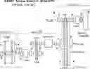
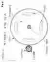
FIG. 1:—Title; “Hydro Torque Electric Generator, (Plan View)
i) shows the entire devise of; a) the drive shaft outer end with mounted paddles, the clutch in the middle and the connecting gear on the inner end; b) the flywheel shaft with connecting gear on the outer end, a transmission in the middle and the flywheel on the inner end, and; c) the power take off shaft with a connecting gear on the outer end, a clutch in the middle and an electric generator on the inner end;
ii) also shows sections A, B & C of the devise identified for detail views.
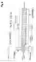
FIG. 2:—Title, “Section A: Drive Shaft End View”
shows the drive Shaft with paddles protruding into a water flow.
FIG. 3:—Title, “Section A: Drive Shaft Side View”
shows the drive shaft with paddles and their mounting structure.
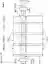
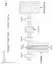
FIG. 4:—Title, “Section B: Transfer System—Plan View”
shows the inter locking gear connection from the inner end of the drive shaft to the outer end gear of the flywheel shaft and a transmission in the middle of the flywheel shaft.
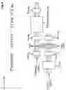
FIG. 5:—Title, “Section C: End View”
shows the flywheel and it's inter locking gear connection to the gear on the outer end of the power take off shaft.
FIG. 6:—Title “Section C: Plan View”
shows the flywheel inter locking gear connection from the flywheel gear to the gear on the outer end of the power take off shaft.
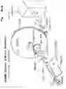
FIG. 7:—Title: “Section D: Power Take Off—Plan View”
shows from a plan view the inter locking gear connection from the flywheel to the power take off shaft gear on the outer end of the power take shaft, the clutch in the middle of the power take off shaft and the electric generator on the inner end of the power take off shaft.
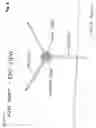
FIG. 8:—Title: “hydro Torque Electric Generator, (conceptual diagram)”
shows from a 3 dimensional view the overall device in a conceptual diagram.
Claims
1. This rotational motion transfer system utilizes 3 parallel shafts, namely;
1)—a Drive Shaft
2)—a Flywheel Shaft
3)—a Power Take off Shaft
to capture the linear motion of a water flow and it's force, creating torque around a rotating shaft, then storing the torque in a flywheel and amplifying the rotational velocity through the rotational motion transfer system of utilizing gear ratios between these 3 shafts before in putting both torque and velocity into an electric generator producing electrical power.
2. The claim of this devise consists of a drive shaft with paddles mounted on the outer end protruding into flowing water, a clutch in the middle and an interlocking gear on the inner end connecting to a gear on the outer end of a flywheel shaft. The flywheel shaft has on the outer end a connecting gear to the drive shaft, a transmission in the middle and a large heavy flywheel on the inner end. The flywheel has gears on it's perimeter interlocking with a gear on the outer end of the power take off shaft. The power take off shaft has an outer end connecting gear to the flywheel shaft gear, a clutch in the middle and an electric generator on the inner end, (See: FIGS. 1-8).
Images & Drawings included:

Sources:
- United States Patent and Trademark Office - verify current appl. status at the USPTO↗
Recent applications in this class:
- » 20250283448 2025-09-11
HIGH-MASS HYDRO ROTOR FOR HYDROELECTRIC POWER GENERATION - » 20250243838 2025-07-31
HYDROPOWER DEVICE COMBINING LIFT AND DRAG EFFECTS - » 20250092853 2025-03-20
HYDROELECTRIC TURBINE - » 20250092852 2025-03-20
A GENERATOR AND A METHOD FOR GENERATING ELECTRICITY WITH A GENERATOR - » 20240191684 2024-06-13
Kinetic machine, powered by flowing water for the extraction of energy by pressurizing water - » 20230228243 2023-07-20
Manufacturing method for hydroelectric power generation system - » 20230184206 2023-06-15
HYDRODYNAMIC TURBINE ROTOR - » 20220220932 2022-07-14
ELECTRICAL ENERGY GENERATION DEVICE - » 20210017954 2021-01-21
Breaking wave power generation - » 20200309086 2020-10-01
Increasing mechanical advantage through the use of a rotating liquid