Portable electronic device
US20110007455A1
2011-01-13
12/603,984
2009-10-22
✅ Patent granted
US 8,254,091 B2
2012-08-28
-
-
Jinhee Lee | Ingrid Wright
2030-11-02
Abstract:
A portable electronic device includes a main body, a battery cover, a resisting portion positioned on the main body, and a latching portion positioned on the main body adjacent to the resisting portion. The battery cover includes a latching protrusion and a positioning portion. The latching protrusion passes over and latches with resisting portion; the positioning portion passes over and latches with latching portion.
Assignee:
- FIH (HONG KONG) LIMITED 1,465 🇭🇰 Kowloon, Hong Kong
- SHENZHEN FUTAIHONG PRECISION INDUSTRY CO., LTD. 1,108 🇨🇳 ShenZhen City, China
- ShenZhen FuTaiHong Precision Industry Co., Ltd. 446 🇨🇳 Shenzhen, Guangdong Province, China
Interested in similar patents?
Get notified when new applications in this technology area are published.
Classification:
H01M50/20 » CPC main
Constructional details or processes of manufacture of the non-active parts of electrochemical cells other than fuel cells, e.g. hybrid cells Mountings; Secondary casings or frames; Racks, modules or packs; Suspension devices; Shock absorbers; Transport or carrying devices; Holders
G06F1/1635 » CPC further
Details not covered by groups - and; Constructional details or arrangements for portable computers; Constructional details or arrangements of portable computers not specific to the type of enclosures covered by groups - Details related to the integration of battery packs and other power supplies such as fuel cells or integrated AC adapter
G06F1/1679 » CPC further
Details not covered by groups - and; Constructional details or arrangements for portable computers; Constructional details or arrangements of portable computers not specific to the type of enclosures covered by groups - ; Miscellaneous details related to the relative movement between the different enclosures or enclosure parts for locking or maintaining the movable parts of the enclosure in a fixed position, e.g. latching mechanism at the edge of the display in a laptop or for the screen protective cover of a PDA
H01M50/244 » CPC further
Constructional details or processes of manufacture of the non-active parts of electrochemical cells other than fuel cells, e.g. hybrid cells; Mountings; Secondary casings or frames; Racks, modules or packs; Suspension devices; Shock absorbers; Transport or carrying devices; Holders Secondary casings; Racks; Suspension devices; Carrying devices; Holders characterised by their mounting method
H01M50/247 » CPC further
Constructional details or processes of manufacture of the non-active parts of electrochemical cells other than fuel cells, e.g. hybrid cells; Mountings; Secondary casings or frames; Racks, modules or packs; Suspension devices; Shock absorbers; Transport or carrying devices; Holders specially adapted for portable devices, e.g. mobile phones, computers, hand tools or pacemakers
H01M50/262 » CPC further
Constructional details or processes of manufacture of the non-active parts of electrochemical cells other than fuel cells, e.g. hybrid cells; Mountings; Secondary casings or frames; Racks, modules or packs; Suspension devices; Shock absorbers; Transport or carrying devices; Holders with fastening means, e.g. locks
H01M50/271 » CPC further
Constructional details or processes of manufacture of the non-active parts of electrochemical cells other than fuel cells, e.g. hybrid cells; Mountings; Secondary casings or frames; Racks, modules or packs; Suspension devices; Shock absorbers; Transport or carrying devices; Holders Lids or covers for the racks or secondary casings
H04M1/0262 » CPC further
Substation equipment, e.g. for use by subscribers; Constructional features of telephone sets; Portable telephone sets, e.g. cordless phones, mobile phones or bar type handsets; Details of the structure or mounting of specific components for a battery compartment
H01M50/209 » CPC further
Constructional details or processes of manufacture of the non-active parts of electrochemical cells other than fuel cells, e.g. hybrid cells; Mountings; Secondary casings or frames; Racks, modules or packs; Suspension devices; Shock absorbers; Transport or carrying devices; Holders; Racks, modules or packs for multiple batteries or multiple cells characterised by their shape adapted for prismatic or rectangular cells
Y02E60/10 » CPC further
Enabling technologies; Technologies with a potential or indirect contribution to GHG emissions mitigation Energy storage using batteries
Y02E60/10 » CPC further
Enabling technologies; Technologies with a potential or indirect contribution to GHG emissions mitigation Energy storage using batteries
Y10T292/0834 » CPC further
Closure fasteners; Bolts; Multiple Sliding
H05K5/00 IPC
Casings, cabinets or drawers for electric apparatus
H05K5/00 IPC
Casings, cabinets or drawers for electric apparatus
H05K7/14 IPC
Constructional details common to different types of electric apparatus Mounting supporting structure in casing or on frame or rack
H05K7/14 IPC
Constructional details common to different types of electric apparatus Mounting supporting structure in casing or on frame or rack
Description
BACKGROUND
1. Technical Field
The present disclosure relates to portable electronic devices and, particularly, to a portable electronic device incorporating a battery cover.
2. Description of Related Art
Portable electronic devices usually include battery covers for covering batteries inside the housings. The battery covers are used frequently when installing and removing batteries.
A typical portable electronic device includes a main body, a battery cover, a button, and a spring. The button is slidably assembled to the main body. The spring abuts between the main body and the button. The button has a protrusion positioned thereon. The battery cover defines a receiving slot therein. The protrusion is engaged in the receiving slot. Thus, the battery cover can be assembled to the main body. In disassembly, the button is pushed and the protrusion is released from the receiving slot. Thus, the battery cover can be disassembled from the main body. However, this kind of the portable electronic device has complex structure, and is inconvenient to operate.
Therefore, there is a room for improvement within the art.
BRIEF DESCRIPTION OF THE DRAWINGS
Many aspects of a portable electronic device can be better understood with reference to the following drawings. The components in the drawings are not necessarily to scale, the emphasis instead being placed upon clearly illustrating the principles of the present portable electronic device. Moreover, in the drawings, like reference numerals designate corresponding parts throughout the several views.
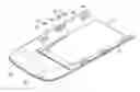
FIG. 1 is a partial isometric view of a portable electronic device according to an exemplary embodiment.
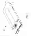
FIG. 2 is an isometric view of a main body of the portable electronic device.
FIG. 3 is an enlarged partial view at III area shown in FIG. 2.
FIG. 4 is an isometric view of a battery cover of the portable electronic device.
FIG. 5 is a partial isometric view of the battery cover latching to the main body.
DETAILED DESCRIPTION OF THE EMBODIMENTS
FIG. 1 shows an exemplary embodiment of a portable electronic device 100, such as a mobile phone, a personal digital assistant (PDA) or etc, including a main body 10, a battery cover 30 detachably assembled to the main body 10.
FIG. 2 shows the main body 10 including a top portion 11, one or more opposite sidewalls 12, an end wall 13 connecting the sidewalls 12, one or more resisting portions 14, one or more latching portions 15, and an engaging portion 17. Main body 10 defines a receiving chamber 18 for receiving a battery (not shown).
The resisting portion 14 and the latching portions 15 are positioned adjacent the peripheral edges of the top portion 11. The resisting portion 14 includes a plate portion 141 and a resisting block 1411. The resisting block 1411 is positioned near a middle portion of the plate portion 141. The resisting block 1411 is wedge-shaped and extends away from a surface of the plate portion 141 and point away from the receiving chamber 18.
Referring to FIG. 3, each of the latching portions 15 defines an accommodating chamber 151 and a stopping block 155 positioned at a corner of the accommodating chamber 151. The accommodating chamber 151 is enclosed by a side 152 and a wall 154 substantially perpendicular to the side 152. The stopping block 155 and the wall 154 define a sliding groove 156 therebetween. The wall 154 defines a latching slot 153 adjacent to the top portion 11. A baffle plate portion 1541 is defined on the wall 154 and extends from a surface of the latching slot 153 to the side 152. The baffle plate portion 1541 can be made of resilient material such as rubber.
The engaging portion 17 is positioned on the top portion 11 and located adjacent to the peripheral of the end wall 13. The engaging portion 17 defines one or more lateral, spaced latching holes 172.
FIG. 4 shows the battery cover 30 including a main portion 31, one or more opposite side plate portions 33, an end plate portion 35 connecting the one or more side plate portions 33, one or more latching protrusions 32, one or more positioning portions 34, and one or more extending blocks 36. The latching protrusions 32 includes a support arm 321, two opposite connecting arms 323, and a projection 325. The support arm 321 can be made of resilient materials such as rubbers. The connecting arms 323 extend oppositely from the two ends of the support arm 321 to connect the support arm 321 to the side plate portion 33. The projection 325 projects from near a middle portion of the support arm 321.
Each of the positioning portions 34 includes a base plate portion 341 and a locking block 345. The base plate portion 341 is positioned on the plate portions 33 adjacent to the latching protrusion 32. The base plate portion 341 can slidably engage within the sliding groove 156. The locking block 345 protrudes from the base plate portion 341. The locking block 345 can latch with the latching slot 153. The extending blocks 36 are positioned on the end of the plate portion 35, and can engage into the latching holes 172.
Referring to FIG. 5, in assembly, the locking block 345 is received in the latching slot 153. Meanwhile, the extending blocks 36 align with the latching holes 172. The battery cover 30 is pushed towards the main body 10 until the locking block 345 abuts the baffle plate portion 1541, and the projection 325 abuts the resisting block 1411. The battery cover 30 is further pushed, and the locking block 345 deforms the baffle plate portion 1541 to pass over the baffle plate portion 1541. The resisting block 1411 deforms the support arm 321 and the projection 325 passes over and latches with resisting block 1411. Meanwhile, the base plate portion 341 is received in the sliding groove 156. The extending blocks 36 engages in the latching holes 172. Accordingly, the battery cover 30 is assembled to the main body 10.
It is to be understood that the resisting portion 14 and the latching portions 15 also can be symmetrically positioned on one or more opposite peripheral edges of the top portion 11. Accordingly, the latching protrusion 32 and positioning portions 34 are symmetrically positioned on one or more opposite side plate portions 33.
It is to be understood, however, that even through numerous characteristics and advantages of the present invention have been set forth in the foregoing description, together with details of the structure and function of the invention, the disclosure is illustrative only, and changes may be made in detail, especially in matters of shape, size, and arrangement of parts within the principles of the invention to the full extent indicated by the broad general meaning of the terms in which the appended claims are expressed.
Claims
What is claimed is:1. A portable electronic device, comprising:
a main body;
a battery cover including a latching protrusion and a positioning portion;
a resisting portion positioned on the main body; and
a latching portion positioned on the main body adjacent to the resisting portion;
wherein the latching protrusion passes over and latches with resisting portion; the positioning portion passes over and latches with latching portion.
2. The portable electronic device as claimed in claim 1, wherein the latching protrusion includes a support arm, two opposite connecting arms, and a projection positioned on the support arm; the connecting arms formed on two ends of the support arm to connect the support arm to the battery cover, the projection abuts the resisting portion.
3. The portable electronic device as claimed in claim 2, wherein the resisting portion includes a plate portion and a resisting block positioned on the plate portion; the resisting block abuts the projection to form the support arm.
4. The portable electronic device as claimed in claim 3, wherein the resisting block is wedge-shaped and positioned near a middle of the plate portion.
5. The portable electronic device as claimed in claim 4, wherein the main body includes a top portion defining a receiving chamber and one or more sidewalls, the resisting portion positioned on the top portion between the receiving chamber and a sidewall, the resisting block extending away from the plate portion and opposite to another sidewall.
6. The portable electronic device as claimed in claim 5, wherein the latching portion defines an accommodating chamber and a stopping block positioned at a corner of the accommodating chamber, a sliding groove is defined in the accommodating chamber; the positioning portion is slidably assembled in the sliding groove and the accommodating chamber.
7. The portable electronic device as claimed in claim 6, wherein the positioning portion includes a base plate portion and a locking block positioned on the base plate portion; the base plate portion is slidable in the sliding groove, the locking block latches in the latching portion.
8. The portable electronic device as claimed in claim 7, wherein a baffle plate portion extends from the latching portion, and abuts the locking block.
9. The portable electronic device as claimed in claim 8, wherein the baffle plate portion and the support arm are made of a resilient material.
10. A portable electronic device, comprising:
a main body;
a battery cover including a latching protrusion and one or more extending blocks; and
a resisting portion positioned on the main body;
wherein the latching protrusion passes over and latches with resisting portion; the extending blocks latch to the main body.
11. The portable electronic device as claimed in claim 10, further comprising a positioning portion positioned on the battery cover and a latching portion positioned on the main body adjacent to the resisting portion, the positioning portion passes the latching portion and latches with the latching portion.
12. The portable electronic device as claimed in claim 11, wherein the latching protrusion includes a support arm, one or more connecting arms, and a projection positioned on the support arm; the connecting arms formed on one or more ends of the support arm to connect the support arm to the battery cover, the projection abuts the resisting portion.
13. The portable electronic device as claimed in claim 12, wherein the resisting portion includes a plate portion and a resisting block positioned on the plate portion; the resisting block abuts the projection to form the support arm.
14. The portable electronic device as claimed in claim 13, wherein the resisting block is wedge-shaped and positioned near a middle of the plate portion.
15. The portable electronic device as claimed in claim 14, wherein the main body includes a top portion defining a receiving chamber and one or more sidewalls, the resisting portion positioned on the top portion between the receiving chamber and a sidewall, the resisting block extending away from the plate portion and opposite to another sidewall.
16. The portable electronic device as claimed in claim 15, wherein the latching portion defines an accommodating chamber and a stopping block positioned at a corner of the accommodating chamber, a sliding groove is defined in the accommodating chamber; the positioning portion is slidably assembled in the sliding groove and the accommodating chamber.
17. The portable electronic device as claimed in claim 16, wherein the positioning portion includes a base plate portion and a locking block positioned on the base plate portion; the base plate portion is slidable in the sliding groove, the locking block latches in the latching portion.
18. The portable electronic device as claimed in claim 17, wherein a baffle plate portion extends from the latching portion, and abuts the locking block.
19. The portable electronic device as claimed in claim 18, wherein the baffle plate portion and the support arm are made of resilient material.
Images & Drawings included:


Sources:
- United States Patent and Trademark Office - verify current appl. status at the USPTO↗
Similar patent applications:
- » 20120329525
Glass substrate of cover glass for portable electronic device, image display unit for portable electronic device, portable electronic device and method of manufacturing glass substrate of cover glass for portable electronic device - » 20100243738
Processing apparatus of portable electronic devices, portable electronic device, and processing system of portable electronic devices - » 20050184953
Thumb-operable man-machine interfaces (MMI) for portable electronic devices, portable electronic devices including the same and methods of operating the same - » 20120033393
Case structure for portable electronic device, portable electronic device and method for manufacturing same - » 20130236192
PORTABLE ELECTRONIC DEVICE, EXTERNAL BASIC DEVICE, METHOD FOR COUPLING THE PORTABLE ELECTRONIC DEVICE TO AN EXTERNAL BASIC DEVICE AND USING THE EXTERNAL BASIC DEVICE FOR COUPLING THE PORTABLE ELECTRONIC DEVICE - » 10608771
Vibrating portable electronic device, method of vibrating a portable electronic device and method of messaging by vibrating a portable electronic device - » 20150085435
Portable type electronic device, portable type electronic device group, and method of manufacturing portable type electronic device - » 20130107431
Lock device for latching different casings of a portable electronic device and portable electronic device therewith - » 20050261022
Method of operating a portable electronic device and portable electronic device - » 20070117597
Mechanical key lock for portable electronic devices and portable electronic devices including the same
Recent applications in this class:
- » 20250038325 2025-01-30
MULTI-PURPOSE BATTERY PACK - » 20240372190 2024-11-07
MOTOR CONTROL FOR GAS ENGINE REPLACEMENT DEVICE - » 20240258620 2024-08-01
COMBUSTION-POWERED FASTENER DRIVING TOOL FUEL CELL ADAPTER - » 20240204315 2024-06-20
COMMERCIAL FLEXIBLE BATTERY PACK WITH SECONDARY OUTPUT CONTROL - » 20240145831 2024-05-02
BATTERY PACK - » 20240097253 2024-03-21
Regenerative electrical power system with state of charge management in view of predicted and/or scheduled stopover auxiliary power requirements - » 20240088497 2024-03-14
Removable Battery Pack - » 20230307752 2023-09-28
BATTERY PACK STRUCTURES AND SYSTEMS - » 20230275294 2023-08-31
Battery pack assembly - » 20230253656 2023-08-10
POWER SOURCE ASSEMBLY FOR AN ELECTRIC VERTICAL TAKE-OFF AND LANDING (EVTOL) AIRCRAFT
Recent applications for this Assignee:
- » 20220140846 2022-05-05
Antenna structure and wireless communication device using same - » 20220094077 2022-03-24
Antenna structure and wireless communication device using same - » 20220059931 2022-02-24
Antenna structure and wireless communication device - » 20220021116 2022-01-20
Single antenna structure capable of operating in multiple band widths - » 20220010948 2022-01-13
Anti-loosing structure and backlight module - » 20200170133 2020-05-28
Housing, electronic device, and method for manufacturing same - » 20200122194 2020-04-23
Frame and surface treatment method for the frame - » 20200060034 2020-02-20
Housing, method for manufacturing the same, and electronic device having the same - » 20200016805 2020-01-16
Housing, electronic device, and method for manufacturing the same - » 20190368052 2019-12-05
COMPOSITE AND METHOD FOR MAKING SAME