Adjustable shim
US20110028061A1
2011-02-03
12/801,826
2010-06-28
✅ Patent granted
US 9,452,588 B2
2016-09-27
-
-
Andrew Piziali
Nixon & Vanderhye P.C.
2034-05-17
Abstract:
An adjustable shim comprises a stack of plies comprising plastics material reinforced with a three-dimensional fibre layer, the plastics material being flowable under compressive force prior to cure for adjusting the thickness of the shim. The shim may be used to fill a void between two structural components joined together. Also, a method of filling a void between two structural components using the shim. The shim is easy to handle, can easily be laid up to a variety of thicknesses, and is quick to cure (depending on the plastics material used). The three-dimensional fibre layers make the shim highly compressible prior to cure, and provide significant reinforcement to the plastics material of the plies to support compressive stresses in the shim post cure.
Inventors:
- Timothy SANDERSON 14 🇬🇧 Bristol, United Kingdom
- Peter Burchell 1 🇬🇧 Winscombe, United Kingdom
Assignee:
- AIRBUS OPERATIONS LIMITED 1,080 🇬🇧 Bristol, United Kingdom
Applicant:
Interested in similar patents?
Get notified when new applications in this technology area are published.
Classification:
B29C65/3476 » CPC further
Joining of preformed parts ; Apparatus therefor by heating, with or without pressure using heated elements which remain in the joint, e.g. "verlorenes Schweisselement" characterised by the composition of the heated elements which remain in the joint being metallic
B29C65/7802 » CPC further
Joining of preformed parts ; Apparatus therefor; Means for handling the parts to be joined, e.g. for making containers or hollow articles, e.g. means for handling sheets, plates, web-like materials, tubular articles, hollow articles or elements to be joined therewith; Means for discharging the joined articles from the joining apparatus Positioning the parts to be joined, e.g. aligning, indexing or centring
B29C66/73756 » CPC further
General aspects of processes or apparatus for joining preformed parts characterised by the composition, physical properties or the structure of the material of the parts to be joined; Joining with non-plastics material characterised by the intensive physical properties of the material of the parts to be joined, by the optical properties of the material of the parts to be joined, by the extensive physical properties of the parts to be joined, by the state of the material of the parts to be joined or by the material of the parts to be joined being a thermoplastic or a thermoset characterised by the state of the material of the parts to be joined uncured, partially cured or fully cured the to-be-joined area of at least one of the parts to be joined being fully cured, i.e. fully cross-linked, fully vulcanized the to-be-joined areas of both parts to be joined being fully cured
B29C66/73116 » CPC further
General aspects of processes or apparatus for joining preformed parts characterised by the composition, physical properties or the structure of the material of the parts to be joined; Joining with non-plastics material characterised by the intensive physical properties of the material of the parts to be joined, by the optical properties of the material of the parts to be joined, by the extensive physical properties of the parts to be joined, by the state of the material of the parts to be joined or by the material of the parts to be joined being a thermoplastic or a thermoset characterised by the intensive physical properties of the material of the parts to be joined; Thermal properties; Melting point of different melting point, i.e. the melting point of one of the parts to be joined being different from the melting point of the other part
B29K2307/04 » CPC further
Use of elements other than metals as reinforcement Carbon
B29K2309/08 » CPC further
Use of inorganic materials not provided for in groups - , as reinforcement Glass
B29K2277/10 » CPC further
Aromatic polyamides [Polyaramides] or derivatives thereof
B29K2071/00 » CPC further
Use of polyethers, e.g. PEEK, i.e. polyether-etherketone or PEK, i.e. polyetherketone or derivatives thereof , as moulding material
B29K2079/085 » CPC further
PI, i.e. polyimides or derivatives thereof Thermoplastic polyimides, e.g. polyesterimides, PEI, i.e. polyetherimides, or polyamideimides; Derivatives thereof
B29K2063/00 » CPC further
Use of epoxy resins , as moulding material
B32B37/10 IPC
Methods or apparatus for laminating, e.g. by curing or by ultrasonic bonding characterised by the pressing technique, e.g. using action of vacuum or fluid pressure
B32B38/10 IPC
Ancillary operations in connection with laminating processes Removing layers, or parts of layers, mechanically or chemically
B29C70/24 » CPC further
Shaping composites, i.e. plastics material comprising reinforcements, fillers or preformed parts, e.g. inserts comprising reinforcements only, e.g. self-reinforcing plastics; Fibrous reinforcements only characterised by the structure of fibrous reinforcements, e.g. hollow fibres using fibres of substantial or continuous length oriented in at least three directions forming a three dimensional structure
B29C65/344 » CPC further
Joining of preformed parts ; Apparatus therefor by heating, with or without pressure using heated elements which remain in the joint, e.g. "verlorenes Schweisselement" characterised by the type of heated elements which remain in the joint being a woven or non-woven fabric or being a mesh
B29C65/3436 » CPC further
Joining of preformed parts ; Apparatus therefor by heating, with or without pressure using heated elements which remain in the joint, e.g. "verlorenes Schweisselement" characterised by the type of heated elements which remain in the joint comprising independent continuous fibre-reinforcements
B29C65/3444 » CPC further
Joining of preformed parts ; Apparatus therefor by heating, with or without pressure using heated elements which remain in the joint, e.g. "verlorenes Schweisselement" characterised by the type of heated elements which remain in the joint being a ribbon, band or strip
B32B5/02 IPC
Layered products characterised by the non- homogeneity or physical structure, i.e. comprising a fibrous, filamentary, particulate or foam layer; Layered products characterised by having a layer differing constitutionally or physically in different parts characterised by structural features of a layer
B29C65/364 » CPC further
Joining of preformed parts ; Apparatus therefor by heating, with or without pressure using heated elements which remain in the joint, e.g. "verlorenes Schweisselement" heated by induction characterised by the type of elements heated by induction which remain in the joint being a woven or non-woven fabric or being a mesh
B29C65/4815 » CPC further
Joining of preformed parts ; Apparatus therefor using adhesives, i.e. using supplementary joining material; solvent bonding characterised by the type of adhesives; Non-reactive adhesives, e.g. physically hardening adhesives Hot melt adhesives, e.g. thermoplastic adhesives
B29C65/5014 » CPC further
Joining of preformed parts ; Apparatus therefor using adhesives, i.e. using supplementary joining material; solvent bonding using adhesive tape, e.g. thermoplastic tape; using threads or the like characterised by the structure of said adhesive tape, threads or the like being fibre-reinforced
B29C65/5021 » CPC further
Joining of preformed parts ; Apparatus therefor using adhesives, i.e. using supplementary joining material; solvent bonding using adhesive tape, e.g. thermoplastic tape; using threads or the like characterised by the structure of said adhesive tape, threads or the like being multi-layered
B29C65/5057 » CPC further
Joining of preformed parts ; Apparatus therefor using adhesives, i.e. using supplementary joining material; solvent bonding using adhesive tape, e.g. thermoplastic tape; using threads or the like positioned between the surfaces to be joined
B29C66/112 » CPC further
General aspects of processes or apparatus for joining preformed parts; General aspects dealing with the joint area or with the area to be joined; Particular design of joint configurations particular design of the joint cross-sections; Joint cross-sections comprising a single joint-segment, i.e. one of the parts to be joined comprising a single joint-segment in the joint cross-section Single lapped joints
B29C66/131 » CPC further
General aspects of processes or apparatus for joining preformed parts; General aspects dealing with the joint area or with the area to be joined; Particular design of joint configurations particular design of the joint cross-sections; Single flanged joints; Fin-type joints; Single hem joints; Edge joints; Interpenetrating fingered joints; Other specific particular designs of joint cross-sections not provided for in groups - Single flanged joints, i.e. one of the parts to be joined being rigid and flanged in the joint area
B29C66/43441 » CPC further
General aspects of processes or apparatus for joining preformed parts; General aspects of joining substantially flat articles, e.g. plates, sheets or web-like materials; Making flat seams in tubular or hollow articles; Joining single elements to substantially flat surfaces; Joining substantially flat articles ; Making flat seams in tubular or hollow articles; Joining a relatively small portion of the surface of said articles; Joining substantially flat articles for forming corner connections, fork connections or cross connections; Joining substantially flat articles for forming fork connections, e.g. for making Y-shaped pieces with two right angles, e.g. for making T-shaped pieces, H-shaped pieces
B29C66/721 » CPC further
General aspects of processes or apparatus for joining preformed parts characterised by the composition, physical properties or the structure of the material of the parts to be joined; Joining with non-plastics material characterised by the structure of the material of the parts to be joined Fibre-reinforced materials
B29C66/72141 » CPC further
General aspects of processes or apparatus for joining preformed parts characterised by the composition, physical properties or the structure of the material of the parts to be joined; Joining with non-plastics material characterised by the structure of the material of the parts to be joined; Fibre-reinforced materials characterised by the length of the fibres Fibres of continuous length
B29C70/28 » CPC further
Shaping composites, i.e. plastics material comprising reinforcements, fillers or preformed parts, e.g. inserts comprising reinforcements only, e.g. self-reinforcing plastics Shaping operations therefor
B32B5/024 » CPC further
Layered products characterised by the non- homogeneity or physical structure, i.e. comprising a fibrous, filamentary, particulate or foam layer; Layered products characterised by having a layer differing constitutionally or physically in different parts characterised by structural features of a layer Woven fabric
B32B5/026 » CPC further
Layered products characterised by the non- homogeneity or physical structure, i.e. comprising a fibrous, filamentary, particulate or foam layer; Layered products characterised by having a layer differing constitutionally or physically in different parts characterised by structural features of a layer Knitted fabric
B32B5/08 » CPC further
Layered products characterised by the non- homogeneity or physical structure, i.e. comprising a fibrous, filamentary, particulate or foam layer; Layered products characterised by having a layer differing constitutionally or physically in different parts characterised by structural features of a layer the fibres or filaments of a layer being of different substances, e.g. conjugate fibres, mixture of different fibres
B32B7/02 » CPC further
Layered products characterised by the relation between layers; Layered products characterised by the relative orientation of features between layers, or by the relative values of a measurable parameter between layers, i.e. products comprising layers having different physical, chemical or physicochemical properties; Layered products characterised by the interconnection of layers Physical, chemical or physicochemical properties
B29C35/02 » CPC further
Heating, cooling or curing, e.g. crosslinking or vulcanising; Apparatus therefor Heating or curing, e.g. crosslinking or vulcanizing during moulding, e.g. in a mould
B29C37/04 » CPC further
Component parts, details, accessories or auxiliary operations, not covered by group or; Deburring or deflashing of welded articles, e.g. deburring or deflashing in combination with welding
B29C65/3676 » CPC further
Joining of preformed parts ; Apparatus therefor by heating, with or without pressure using heated elements which remain in the joint, e.g. "verlorenes Schweisselement" heated by induction characterised by the composition of the elements heated by induction which remain in the joint being metallic
B29C66/71 » CPC further
General aspects of processes or apparatus for joining preformed parts characterised by the composition, physical properties or the structure of the material of the parts to be joined; Joining with non-plastics material characterised by the composition of the plastics material of the parts to be joined
B29C66/7212 » CPC further
General aspects of processes or apparatus for joining preformed parts characterised by the composition, physical properties or the structure of the material of the parts to be joined; Joining with non-plastics material characterised by the structure of the material of the parts to be joined; Fibre-reinforced materials characterised by the composition of the fibres
B29C66/7392 » CPC further
General aspects of processes or apparatus for joining preformed parts characterised by the composition, physical properties or the structure of the material of the parts to be joined; Joining with non-plastics material characterised by the intensive physical properties of the material of the parts to be joined, by the optical properties of the material of the parts to be joined, by the extensive physical properties of the parts to be joined, by the state of the material of the parts to be joined or by the material of the parts to be joined being a thermoplastic or a thermoset characterised by the material of the parts to be joined being a thermoplastic or a thermoset characterised by the material of at least one of the parts being a thermoplastic
B29C66/7394 » CPC further
General aspects of processes or apparatus for joining preformed parts characterised by the composition, physical properties or the structure of the material of the parts to be joined; Joining with non-plastics material characterised by the intensive physical properties of the material of the parts to be joined, by the optical properties of the material of the parts to be joined, by the extensive physical properties of the parts to be joined, by the state of the material of the parts to be joined or by the material of the parts to be joined being a thermoplastic or a thermoset characterised by the material of the parts to be joined being a thermoplastic or a thermoset characterised by the material of at least one of the parts being a thermoset
B29C66/73752 » CPC further
General aspects of processes or apparatus for joining preformed parts characterised by the composition, physical properties or the structure of the material of the parts to be joined; Joining with non-plastics material characterised by the intensive physical properties of the material of the parts to be joined, by the optical properties of the material of the parts to be joined, by the extensive physical properties of the parts to be joined, by the state of the material of the parts to be joined or by the material of the parts to be joined being a thermoplastic or a thermoset characterised by the state of the material of the parts to be joined uncured, partially cured or fully cured the to-be-joined area of at least one of the parts to be joined being uncured, i.e. non cross-linked, non vulcanized the to-be-joined areas of both parts to be joined being uncured
B29C66/73921 » CPC further
General aspects of processes or apparatus for joining preformed parts characterised by the composition, physical properties or the structure of the material of the parts to be joined; Joining with non-plastics material characterised by the intensive physical properties of the material of the parts to be joined, by the optical properties of the material of the parts to be joined, by the extensive physical properties of the parts to be joined, by the state of the material of the parts to be joined or by the material of the parts to be joined being a thermoplastic or a thermoset characterised by the material of the parts to be joined being a thermoplastic or a thermoset characterised by the material of at least one of the parts being a thermoplastic characterised by the materials of both parts being thermoplastics
B29C66/73941 » CPC further
General aspects of processes or apparatus for joining preformed parts characterised by the composition, physical properties or the structure of the material of the parts to be joined; Joining with non-plastics material characterised by the intensive physical properties of the material of the parts to be joined, by the optical properties of the material of the parts to be joined, by the extensive physical properties of the parts to be joined, by the state of the material of the parts to be joined or by the material of the parts to be joined being a thermoplastic or a thermoset characterised by the material of the parts to be joined being a thermoplastic or a thermoset characterised by the material of at least one of the parts being a thermoset characterised by the materials of both parts being thermosets
B29C66/8322 » CPC further
General aspects of processes or apparatus for joining preformed parts; General aspects of machine operations or constructions and parts thereof characterised by the movement of the joining or pressing tools; Reciprocating joining or pressing tools Joining or pressing tools reciprocating along one axis
B32B2260/021 » CPC further
Layered product comprising an impregnated, embedded, or bonded layer wherein the layer comprises an impregnation, embedding, or binder material; Composition of the impregnated, bonded or embedded layer Fibrous or filamentary layer
B32B2260/046 » CPC further
Layered product comprising an impregnated, embedded, or bonded layer wherein the layer comprises an impregnation, embedding, or binder material; Impregnation, embedding, or binder material Synthetic resin
B32B2262/106 » CPC further
Composition or structural features of fibres which form a fibrous or filamentary layer or are present as additives; Inorganic fibres Carbon fibres, e.g. graphite fibres
B32B2262/14 » CPC further
Composition or structural features of fibres which form a fibrous or filamentary layer or are present as additives Mixture of at least two fibres made of different materials
B32B2307/50 » CPC further
Properties of the layers or laminate having particular mechanical properties
B32B2307/58 » CPC further
Properties of the layers or laminate having particular mechanical properties Cuttability
B32B2605/18 » CPC further
Vehicles Aircraft
Y10T428/249921 » CPC further
Stock material or miscellaneous articles Web or sheet containing structurally defined element or component
Y10T442/3195 » CPC further
Fabric [woven, knitted, or nonwoven textile or cloth, etc.]; Woven fabric [i.e., woven strand or strip material]; Woven fabric is characterized by a particular or differential weave other than fabric in which the strand denier or warp/weft pick count is specified Three-dimensional weave [e.g., x-y-z planes, multi-planar warps and/or wefts, etc.]
Y10T442/45 » CPC further
Fabric [woven, knitted, or nonwoven textile or cloth, etc.]; Knit fabric [i.e., knit strand or strip material] Knit fabric is characterized by a particular or differential knit pattern other than open knit fabric or a fabric in which the strand denier is specified
B32B5/26 » CPC main
Layered products characterised by the non- homogeneity or physical structure, i.e. comprising a fibrous, filamentary, particulate or foam layer; Layered products characterised by having a layer differing constitutionally or physically in different parts characterised by the presence of two or more layers which are next to each other and are fibrous, filamentary, formed of particles or foamed one layer being a fibrous or filamentary layer another layer also being fibrous or filamentary
B29C65/4835 » CPC further
Joining of preformed parts ; Apparatus therefor using adhesives, i.e. using supplementary joining material; solvent bonding characterised by the type of adhesives; Reactive adhesives, e.g. chemically curing adhesives Heat curing adhesives
B29C43/00 IPC
Compression moulding, i.e. applying external pressure to flow the moulding material; Apparatus therefor
B29C65/34 IPC
Joining of preformed parts ; Apparatus therefor by heating, with or without pressure using heated elements which remain in the joint, e.g. "verlorenes Schweisselement"
B29C65/36 IPC
Joining of preformed parts ; Apparatus therefor by heating, with or without pressure using heated elements which remain in the joint, e.g. "verlorenes Schweisselement" heated by induction
B29C65/50 IPC
Joining of preformed parts ; Apparatus therefor using adhesives, i.e. using supplementary joining material; solvent bonding using adhesive tape, e.g. thermoplastic tape; using threads or the like
B29C65/00 IPC
Joining of preformed parts ; Apparatus therefor
B29C65/48 IPC
Joining of preformed parts ; Apparatus therefor using adhesives, i.e. using supplementary joining material; solvent bonding
B32B5/22 » CPC further
Layered products characterised by the non- homogeneity or physical structure, i.e. comprising a fibrous, filamentary, particulate or foam layer; Layered products characterised by having a layer differing constitutionally or physically in different parts characterised by the presence of two or more layers which are next to each other and are fibrous, filamentary, formed of particles or foamed
B32B2262/0269 » CPC further
Composition or structural features of fibres which form a fibrous or filamentary layer or are present as additives; Synthetic macromolecular fibres; Polyamide fibres Aromatic polyamide fibres
B29C65/3636 » CPC further
Joining of preformed parts ; Apparatus therefor by heating, with or without pressure using heated elements which remain in the joint, e.g. "verlorenes Schweisselement" heated by induction characterised by the type of elements heated by induction which remain in the joint comprising independent continuous fibre-reinforcements
B32B5/12 » CPC further
Layered products characterised by the non- homogeneity or physical structure, i.e. comprising a fibrous, filamentary, particulate or foam layer; Layered products characterised by having a layer differing constitutionally or physically in different parts characterised by structural features of a layer characterised by the relative arrangement of fibres or filaments of different layers, e.g. the fibres or filaments being parallel or perpendicular to each other
B29L2031/3076 » CPC further
Other particular articles; Vehicles, e.g. ships or aircraft, or body parts thereof Aircrafts
B32B2262/101 » CPC further
Composition or structural features of fibres which form a fibrous or filamentary layer or are present as additives; Inorganic fibres Glass fibres
Description
FIELD OF THE INVENTION
The present invention relates to an adjustable shim for filling a void between two structural components.
BACKGROUND OF THE INVENTION
Voids between structural components have been a common problem since the start of aviation. This has consistently been caused by the manufacturing tolerances of the components in question not being sufficiently tight to allow for a good interface to be made. This situation has been made significantly worse by the introduction of composite materials where some of the manufacturing processes give downgraded tolerance performances.
Currently there are a number of ways to solve this problem. All of which are time consuming and expensive. These are:
1. Assembling the components, measuring the void and fixing packing pieces into the measured void. Any packing pieces have to be bonded or mechanically fastened in position to ensure they do not detach in service.
2. Applying a structural filler (liquid shim) to the joint during assembly, ensuring it fully covers the void with minimal air pockets. When applied the excess material that has extruded out of the sides has to be cleared up and then the shim requires a significant amount of time to harden (cure), during which time the components cannot be moved. Liquid shim can typically only be used to fill voids of less than around 1.25 mm.
3. Including within one of the components an excess of material which is fettled/filed to match the surface of the other component on assembly, again taking significant time by a skilled workforce.
4. In the case of laminate composite components, if these are found to be of insufficient dimension upon assembly to other components, additional plies can be added after the component has been cured. This then requires a re-cure of the component to incorporate the additional plies. This is costly and significantly extends the assembly time.
SUMMARY OF THE INVENTION
A first aspect of the invention provides an adjustable shim comprising a stack of plies comprising plastics material reinforced with a three-dimensional fibre layer, the plastics material being flowable under compressive force prior to cure for adjusting the thickness of the shim.
A second aspect of the invention provides an assembly comprising two structural components joined together and a shim in accordance with the first aspect filling a void between the structural components.
A third aspect of the invention provides a method of filling a void between two structural components to be joined together, the method comprising: attaching an adjustable shim to a mating surface of one of the components, wherein the adjustable shim comprises a stack of plies comprising plastics material reinforced with a three-dimensional fibre layer, the plastics material being flowable under compressive force prior to cure for adjusting the thickness of the shim; aligning the two components to a predetermined orientation so as to compress the shim and thereby adjust the shim thickness to fill a void between the two components; and curing the shim.
The present invention is advantageous in that the shim is easy to handle, can easily be laid up to a variety of thicknesses, and is quick to cure (depending on the plastics material used). The three-dimensional fibre layers provide significant reinforcement to the plastics material of the plies to support compressive stresses in the shim post cure. The shim readily fills the void between the structural components and so air pockets are easily avoided without requiring large excesses of shim material. This is primarily due to the 3-D fibre reinforcement layers which are highly adaptable. The shim can be configured to bond to one or both of the structural components during cure such that no additional bonding or fixing steps are required to prevent detachment in service. Little or no further handling of the shim or the structural components is required post cure. The shim may be provided as a sheet which can be cut to the required size. Different thickness sheets can be provided with greater or fewer fibre-reinforced plastic plies for selection depending on the size of the void to be filled. Alternatively, the shim may be constructed in situ from as many plies as necessary to achieve the required thickness, as the curing step can be used to bond the pieces together. The heating element(s) may need to be laid up between these plies. The thickness of the shim may be much greater than that capable with liquid shim.
The shim may include one or more heating elements. These may be embedded in individual composite plies or disposed between adjacent composite plies. The plastics material is either thermoplastic or thermosetting plastics material. Where the plastics material is thermoplastic, the heating elements may be energised to make the thermoplastic material flowable. The thermoplastic material will cure once the heat source is removed. Where the plastics material is thermosetting, the heating elements may be energised to cure the thermoset material. Due to the high temperatures involved, particularly with thermoplastic, it may be appropriate to provide one or more heat shields within the shim.
The fibre layers may be woven or knit. The fibre layers may have upstanding yarns to improve compressibility of the fibre layers prior to cure. In particular the fibre layers may have a towelling weave, which is particularly compressible. Alternatively, adjacent fibre layers may be woven together by their upstanding yarns. The fibre layers may include fibres of carbon, glass, or Kevlar, for example. The fibre layers may include a single fibre material, or a mixture of fibre materials woven or knit together in any suitable ratio. For example, a knit hybrid fabric with a ratio of five glass to one carbon fibres may be used.
In the assembly of the second aspect, the two structural components may be an aircraft wing box rib and a wing cover. However, the two structural components may be virtually any components in an aerospace or non-aerospace application where a void between the components needs to be filled with a structural filler.
In the method of the third aspect, the curing step may be used to bond the two structural components together to form a joint. For example, the shim may be used in a thermoplastic welding operation to join two thermoplastic structural components. Alternatively, the shim may be used to co-cure two fibre-reinforced resin composite components.
As some of the flowable plastics material will extrude from the sides of the shim under the compressive force applied, this excess material may need to be removed prior to curing the shim. Alternatively, this excess material could be cut away from the shim after cure. If only a small amount of material is extruded, it may be acceptable for this to be left in situ.
BRIEF DESCRIPTION OF THE DRAWINGS
Embodiments of the invention will now be described with reference to the accompanying drawings, in which:
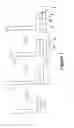
FIG. 1 illustrates the steps of joining a wing box rib to a wing cover with an adjustable shim initially attached to the rib for filling a void between the two components;
FIG. 2 illustrates an alternative series of steps for joining the wing box rib to the wing cover with the adjustable shim initially attached to the cover;
FIG. 3 illustrates schematically the adjustable shim comprising two 3-D fibre reinforced plastic plies with a heating element disposed between them;
FIG. 4 illustrates schematically deformation of the shim under compressive load;
FIG. 5 illustrates in detail the 3-D fibre layers;
FIG. 6 illustrates schematically an alternative shim arrangement including heat shields; and
FIG. 7 illustrates schematically an alternative shim arrangement in which adjacent fibre layers are woven together.
DETAILED DESCRIPTION OF EMBODIMENT(S)
FIG. 1 shows the steps of joining a rib 1 to a lower cover 2 of an aircraft wing box. As shown in FIG. 1a), the rib 1 has a foot 3 for attaching the rib 1 to the cover 2. The rib 1 is aligned with the cover 2 (not shown in FIG. 1a)) to determine the extent of the void between the two components which is to be filled when the components are joined. An adjustable shim 4 having a thickness greater than that of the void is attached to the underside of the rib foot 3, as shown in FIG. 1b). The rib 1 and the cover 2 are brought together once again as shown in FIG. 1c), until the rib 1 and cover 2 are correctly aligned as shown in FIG. 1d). A jig (not shown) may be used to align the components, if necessary.
As can be seen from FIG. 1d), the shim 4 is compressed when the rib 1 and cover 2 are correctly aligned. Some of the shim material is extruded from the sides 5 under the compressive load. The compressive load is applied to the shim 4 by the weight of the rib 1 alone, or with additional compressive load provided manually or by a jig/tooling. The shim 4 includes a stack of plies of plastics material reinforced with a three-dimensional fibre layer. The plastics material is flowable under the compressive load to adjust the thickness of the shim 4 to closely fill the void between the rib 1 and the cover 2. Once the thickness of the shim 4 has been adjusted in this way, the shim is cured such that the plastics material is no longer flowable in normal use.
FIG. 2 shows an alternative series of steps for joining the rib 1 to the cover 2. The rib 1 and the cover 2 are initially aligned to determine the extent of the void to be filled, as before. With the cover 2 in place, as shown in FIG. 2a), a suitable thickness of shim 4 is attached to the upper surface of the cover 2, as shown in FIG. 2b). The rib 1 and the cover 2 are then brought together once again as shown in FIG. 2c), until the rib 1 and cover 2 are correctly aligned. A jig (not shown) may be used to align the components, if necessary.
As can be seen from FIG. 2c), the shim 4 is compressed when the rib 1 and cover 2 are correctly aligned. The thickness of the shim 4 is adjusted under the compressive load during alignment of the two components causing some of the shim material to be extruded from the sides 5, as before. With the rib 1 and cover 2 correctly aligned as shown in FIG. 2d), the shim 4 is cured such that the plastics material in the shim is no longer flowable in normal use.
Once the shim 4 has cured following the steps described above with reference to FIG. 1 or FIG. 2, the rib 1 and cover 2 are drilled and bolted to join them together to form the completed joint.
The shim 4 will now be described in detail with reference to FIGS. 3 to 5. As shown in FIG. 3, the shim 4 includes two plies of plastics material 6, each reinforced with a three-dimensional fibre layer 7. The fibre layers 7 include a substantially two-dimensional mat 8 with an array of fibre yarns 9 extending therefrom. The two fibre layers 7 are oriented oppositely such that the fibre yarns 9 extend away from one another, with the two-dimensional mats 8 lying back-to-back. Between the two plies is an electrical heating element 10.
The shim 4 may be constructed in situ by laying up the plies and the electrical heating element 10 as shown. A greater number of plies and heating elements may be laid up as required. Alternatively, the shim 4 may be pre-prepared. The shim and/or the individual plies may be cut from sheet material.
The plastics material 6 of the plies is a thermosetting epoxy polymer. The fibre layers 7 are woven carbon fibres. The uncured epoxy is pre-impregnated into the fibre layers as so-called “prepreg” plies supplied in “wet” form.
FIG. 4 shows the effect of applying compressive load L to the shim 4 during alignment of the rib 1 and cover 2. The wet prepreg plies reduce in thickness as the epoxy 6 is extruded out from the sides 5. The upstanding fibre yarns 9 are compressed so reduce in height. Once the thickness of the shim 4 has been adjusted to closely fill the void between the rib 1 and the cover 2, the electrical heating element 10 is energized, which heats the shim 4 to cure the epoxy 6 in situ. The supply of current to the heating element 10 is carefully controlled using a temperature control device (not shown) to ensure sufficient energy is supplied only to cure the epoxy.
The heating element 10 is an array of metallic conductive heating wires in a two-dimensional mesh. By embedding the heating element 10 in the shim 4, the heating of the shim can be localised. This is important as excessive non-localised heating could cause thermal expansion problems in the rib 1 and cover 2, leading to tolerance issues. Moreover, the rib 1 and cover 2 are each made from carbon fibre-reinforced epoxy composite similar to that of the shim 4. Although the composite rib 1 and cover 2 are each cured components prior to the assembly process described above, excessive heating of these composite components could lead to their softening and deformation, which also would give rise to tolerance issues.
A significant excess of epoxy extruded from the sides 5 of the shim will need to be removed prior to cure. However, a small amount of extrusion will normally not interfere with the joint being formed.
FIG. 5 shows the fibre layers 7 and the mesh heating element 10 in detail. The fibre layers 7 are woven as a highly compressible towelling weave. The twists of upstanding yarns 9 extend from the woven substantially two-dimensional mat 8. The upstanding yarns 9 are what makes the woven fibre layers 7 so compressible, and hence suitable for use in the adjustable shim 4. The fibre layers 7 are particularly important as they must be capable of withstanding large compressive stresses post cure. The three-dimensional fibre layers 7 provide significant reinforcement to the plastics material 6 of the plies to support these compressive stresses. The towelling weave in particular provides good orientation of fibres in the through thickness direction of the shim 4.
Many alternatives within the scope of this invention are envisaged, some of which will be elaborated here. Others will be apparent to those skilled in the art.
The thermosetting plastics material of the prepreg plies may be selected to be curable at room temperature, which would negate the need for the electrical heating element to be embedded between the plies of the shim. Some thermosetting epoxies would be suitable, but would need to be kept cool prior to use to prevent premature curing of the shim.
The thermosetting plastics material of the prepreg plies of the shim may have a different melting temperature to that used in the composite structural components (the rib and cover, for example) to which it is applied. If heating of the shim to cure it would lead to softening of either of the structural components, then it may be necessary to provide a heat shield on one of both sides of the shim. FIG. 6 illustrates schematically the composition of a shim having heat shields. The shim 20 includes a heating element 21 disposed between a pair of three-dimensional fibre-reinforced thermosetting plastic plies 22. Attached to the outer surfaces of each of the plies 22 is a heat shield 23. The heating element 21 and the plies 22 may be similar to those of the shim 4. The heat shields 23 may comprise ceramic, metal or thermoplastic material, for example. The heat shields 23 protect the composite structural components either side of the shim 20 from heat deformation when the heating element 21 is energized to cure the plies 22.
Where heat shields are used, it may be necessary to provide an “interfay” sealant and/or structural attachment between the shim and the composite structures. The interfay sealant is provided between the mating surfaces of the shim and the structural component to prevent moisture ingress and resulting material degradation which would otherwise occur. The structural attachment retains the shim in place. In some circumstances it may be beneficial to omit the heat shields 23 such that the shim is co-cured to the structural components to form a mechanical bond between the shim and at least one of the structural components to retain the shim in place.
Where a heat source is required to cure the thermosetting plastics material at elevated temperatures, this may be achieved by other means than resistance heating. For example, the conductive metallic mesh previously described may be heated using an induction technique. Both the resistance heating and induction heating techniques provide localised heating, which can be advantageous where the structural components are susceptible to heat deformation. Where this is not an issue, for example, where the melting temperature of the structural components is significantly higher than that required to cure the thermoplastic shim material, then other techniques become available. These include, but are not limited to, heat lamps, ultrasonic heating, and ovens.
The reinforcing fibres in the plies of the shim could be made of other materials than carbon. For example, the fibres could be of glass. A glass/epoxy composite ply would exhibit good electrical insulation properties. The fibre layers could be woven from a mixture of carbon and glass fibres. For example, a ratio of five glass to one carbon fibres could be used to provide a hybrid woven fabric.
As an alternative to a woven fibre layer, the reinforcing fibres may be knitted. A knitted layer would also provide good compressible properties and a three-dimensional structure. An alternative woven ply for the adjustable shim is shown in FIG. 7. The ply 30 includes a pair of woven two-dimensional layers 31 woven together by upstanding fibre yarns 32. The ply 30 is pre-impregnated with a thermosetting plastic 33, such as epoxy. A heating element 34 similar to the heating element 10 is embedded in the ply 30 for curing the plastic 33, although this is optional. The ply 30 is highly compressible due to the compressibility of the upstanding fibre yarns 32.
Instead of thermosetting plastics, the plies of the shim may include thermoplastic reinforced with a three-dimensional fibre layer. Thermoplastics can offer many advantages over thermosetting plastics. For example, a fibre-reinforced thermoplastic shim could be used in a thermoplastic welding operation to join the shim to the composite structural components. Thermoplastic shim would provide improved through thickness compressible strength compared with the thermosetting shim described above. Suitable thermoplastics are polyamide, PEEK and PEI, for example. The thermoplastic material could be used to replace the thermosetting plastic in any of the examples described here.
Whereas heat is used to cure the thermosetting plastic in the shims described above, heat would need to be used to make the thermoplastic in the shim flowable prior to cure. In other words, the heat would need to be applied to the shim as the structural components are brought into alignment such that the thickness of the shim becomes adjustable. Once the structural components are aligned, the heat can be removed allowing the thermoplastic to cool and cure at the desired thickness.
The melting temperature of most suitable thermoplastics is around 400 degrees Celsius, some 200 degrees higher than that of the equivalent thermosetting plastics. Heat shields such as those described previously will therefore need to be used with the thermoplastic shim, unless a thermoplastic welding operation is desirable to join the shim to one or both of the structural components. Heat may applied using any of the induction, ultrasonic, or resistance heating methods described above to provide localised heating of the thermoplastic plies.
In the above embodiments, the structural components are of composite but these may be of more traditional metallic construction, such as Aluminium. As Aluminium tends to soften at around 200 degrees Celsius, the shim may need to be heat shielded to prevent heat deformation of the Aluminium structural components. Furthermore, most Aluminium alloys are carefully heat treated to control their material properties. By raising their temperature to even below their softening temperature may result in a degradation of these material properties. Accordingly heat shielding of the shim may be required to protect the Aluminium structural components at temperatures well below 200 degrees Celsius.
Although the invention has been described above with reference to one or more preferred embodiments, it will be appreciated that various changes or modifications may be made without departing from the scope of the invention as defined in the appended claims.
Claims
1. An adjustable shim comprising a stack of plies comprising plastics material reinforced with a three-dimensional fibre layer, the plastics material being flowable under compressive force prior to cure for adjusting the thickness of the shim.
2. A shim according to claim 1, further comprising one or more heating elements.
3. A shim according to claim 1, wherein the fibre layers are woven or knit.
4. A shim according to claim 3, wherein the fibre layers have a towelling weave.
5. A shim according to claim 3, wherein the fibre layers have upstanding yarns.
6. A shim according to claim 5, wherein adjacent fibre layers are woven together by their upstanding yarns.
7. A shim according to claim 1, wherein the plastics material is either thermoplastic or thermosetting plastics material.
8. A shim according to claim 1, further comprising one or more heat shields.
9. An assembly comprising two structural components joined together and a shim in accordance with claim 1 filling a void between the structural components.
10. An assembly according to claim 9, wherein the two structural components are an aircraft wing box rib and a wing cover.
11. A method of filling a void between two structural components to be joined together, the method comprising:
attaching an adjustable shim to a mating surface of one of the components, wherein the adjustable shim comprises a stack of plies comprising plastics material reinforced with a three-dimensional fibre layer, the plastics material being flowable under compressive force prior to cure for adjusting the thickness of the shim;
aligning the two components to a predetermined orientation so as to compress the shim and thereby adjust the shim thickness to fill a void between the two components; and
curing the shim.
12. A method according to claim 11, wherein the plastics material is either thermoplastic or thermosetting plastics material.
13. A method according to claim 12, wherein the shim includes one or more heating elements, and the method further comprises either:
energising the heating elements to make the thermoplastic material flowable prior to aligning the components where the plies include thermoplastic material; or
energising the heating elements to cure the thermoset material where the plies include thermoset material.
14. A method according to claim 11, wherein the curing step bonds the two structural components together to form a joint.
15. A method according to claim 11, further comprising removing excess plastics material extruded from the shim when compressed.
16. A method according to claim 11, wherein the three-dimensional fibre layers are compressed when the shim is compressed.
Images & Drawings included:


Sources:
- United States Patent and Trademark Office - verify current appl. status at the USPTO↗
Similar patent applications:
- » 20100194009
Substrate holding platen with adjustable shims - » 20110089943
Magnetic field shimming adjustment: reducing magnetic distribution errors by obtaining current potential distributions of MRI apparatus - » 20080286097
Support bar with adjustable shim design for turbine diaphragms - » 20090044463
Adjustable shim - » 20060251514
Adjustable support bar with adjustable shim design for steam turbine diaphragms - » 20070189893
Methods and apparatus for nozzle carrier with trapped shim adjustment - » 20050272211
Adjustable shims and washers - » 20080029680
ADJUSTABLE SHIM - » 20080075556
Adjustable shim - » 20120063760
Optical system with adjustable shims
Recent applications in this class:
- » 20250282118 2025-09-11
PROTECTIVE COMPOSITE FABRICS AND METHODS OF MANUFACTURE AND USE - » 20250269625 2025-08-28
COMPOSITE SOUND-ABSORBING MATERIAL - » 20250262840 2025-08-21
LAMINATED ADHESIVE TAPE AND COMPOSITION THEREFOR - » 20250187300 2025-06-12
AEROSPACE THERMAL ACOUSTIC FIBERGLASS INSULATION USEFUL IN SUPPORTING APPLICATIONS BACKGROUND - » 20250144911 2025-05-08
HIGH-DURABILITY DUAL COMPOSITE WATERPROOF STRUCTURE THROUGH INORGANIC ELASTIC UNDERCOAT BODY AND COMPOSITE SHEET WATERPROOF STRUCTURE WITH HEAT SHIELDING AND HEAT DISSIPATION PERFORMANCE - » 20250100247 2025-03-27
COMPOSITE LAMINATE BODY AND DISPOSABLE DIAPER - » 20250083408 2025-03-13
STRETCHY THERMAL INSULATION COMPOSITE MATERIAL - » 20250042128 2025-02-06
CELLULOSE PRECURSOR MATERIAL AND APPARATUS AND METHOD FOR FIELD CONVERSION OF THE PRECURSOR INTO CELLULOSE INSULATION - » 20250026104 2025-01-23
POROSITY GRADIENT PREFORM ARCHITECTURE FOR HIGH TEMPERATURE COMPOSITES - » 20250026103 2025-01-23
POROSITY GRADIENT PREFORM ARCHITECTURE FOR HIGH TEMPERATURE COMPOSITES
Recent applications for this Assignee:
- » 20250065357 2025-02-27
APPLICATOR - » 20250039266 2025-01-30
AVIONICS UNIT - » 20240336351 2024-10-10
Wing tip device - » 20240327037 2024-10-03
PINTLE SUPPORT AND METHOD OF INSTALLING A LANDING GEAR ASSEMBLY - » 20240286762 2024-08-29
METHOD OF FABRICATING AN AIRCRAFT STRUCTURAL COMPONENT - » 20240253772 2024-08-01
SPOILER - » 20240253766 2024-08-01
AIRCRAFT ASSEMBLY WITH MOVEABLE DEVICE - » 20240239516 2024-07-18
AIRCRAFT SUB-ASSEMBLY MANUFACTURING SYSTEM AND METHOD - » 20240227751 2024-07-11
CONTROL DEVICE AND METHOD FOR AN AIRCRAFT - » 20240208641 2024-06-27
AIRCRAFT STRUCTURE COMPONENT FOR LAMINAR FLOW