LIGHTING ASSEMBLY
US20110032699A1
2011-02-10
12/538,219
2009-08-10
Abstract:
In an embodiment, a lighting assembly includes a first lighting module including a plurality of light-emitting diodes (LEDs) and a plurality of optical elements. Each optical element is configured to refract light emitted by a corresponding one of the LEDs. The assembly further includes a cooling assembly adjacent the lighting module and configured to cool the first lighting module.
Assignee:
- HONEYWELL INTERNATIONAL INC. 9,370 🇺🇸 Morristown, NJ, United States
Interested in similar patents?
Get notified when new applications in this technology area are published.
Classification:
F21V29/773 » CPC main
Protecting lighting devices from thermal damage; Cooling or heating arrangements specially adapted for lighting devices or systems; Cooling arrangements characterised by passive heat-dissipating elements, e.g. heat-sinks with fins or blades with essentially identical diverging planar fins or blades, e.g. with fan-like or star-like cross-section the planes containing the fins or blades having the direction of the light emitting axis
F21K9/20 » CPC further
Light sources using semiconductor devices as light-generating elements, e.g. using light-emitting diodes [LED] or lasers Light sources comprising attachment means
F21V19/04 » CPC further
Fastening of light sources or lamp holders with provision for changing light source, e.g. turret
F21V23/003 » CPC further
Arrangement of electric circuit elements in or on lighting devices the elements being electronics drivers or controllers for operating the light source, e.g. for a LED array
F21V29/677 » CPC further
Protecting lighting devices from thermal damage; Cooling or heating arrangements specially adapted for lighting devices or systems; Cooling arrangements characterised by the use of a forced flow of gas, e.g. air characterised by the arrangement of fans the fans being used for discharging
F21Y2105/10 » CPC further
comprising a two-dimensional array of point-like light-generating elements
F21Y2115/10 » CPC further
Light-generating elements of semiconductor light sources Light-emitting diodes [LED]
F21V5/00 IPC
Refractors for light sources
Description
BACKGROUND OF THE INVENTION
PAR-64 lamps are known for their ability to provide intense illumination. However, incandescent or halogen-based PAR-64 sealed-beam lamps have a short life and are throw-away items.
SUMMARY OF THE INVENTION
In an embodiment, a lighting assembly includes a first lighting module including a plurality of light-emitting diodes (LEDs) and a plurality of optical elements. Each optical element is configured to refract light emitted by a corresponding one of the LEDs. The assembly further includes a cooling assembly adjacent the lighting module and configured to cool the first lighting module.
BRIEF DESCRIPTION OF THE DRAWINGS
Preferred and alternative embodiments are described in detail below with reference to the following drawings:
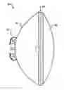
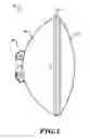
FIG. 1 illustrates a side view of a lighting assembly according to an embodiment of the invention;
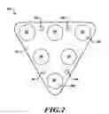
FIG. 2 illustrates a top plan view of a lighting module according to an embodiment;
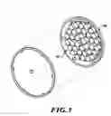
FIG. 3 illustrates an exploded front perspective view of an embodiment; and
FIG. 4 illustrates a rear perspective view of an embodiment.
DETAILED DESCRIPTION OF THE PREFERRED EMBODIMENT
FIG. 1 illustrates a side view of a lighting assembly 10 according to an embodiment of the invention. Assembly 10 includes a main casing 20, a primary lens 30, and a rear casing 40 on which are mounted power terminals 50. Assembly 10 may be of a conventional PAR-64 configuration.
FIG. 2 illustrates a top plan view of a lighting module 60 according to an embodiment and configured to be a constituent element of the assembly 10. The module 60 includes a substantially planar platform member 70, which may be composed of plastic, metal, glass, or a combination of such materials, or any other appropriate material. The module 60 further includes a plurality of light-emitting diodes (LEDs) 90 disposed on the platform member 70. In an embodiment, the LEDs 90 may include a combination of one or more of red, green, blue and white LEDs. The module 60 further includes a plurality of optical elements 100 coupled to the LEDs 90, or otherwise situated with respect to the LEDs, so as to refract light emitted by a corresponding one of the LEDs. In an embodiment, the optical elements 100 include collimating lenses, although other types of optical elements can be employed to customize performance of the assembly 10.
The platform member 70 includes at least one attachment element 80, which may take the form of a borehole. As such, the attachment element(s) 80 are configured to enable removable attachment of the platform member 70 to a surface of the main casing 20 by screws (not shown) or other appropriate temporary fasteners.
FIG. 3 illustrates an exploded front perspective view of the main casing 20 and primary lens 30. As can be seen in FIG. 3, an embodiment includes an array of lighting modules 60 positioned so as to emit light through the primary lens 30. By virtue of the attachment elements 80 associated with each module 60 of the array, a user of the assembly 10 may conveniently remove a faulty module 60 and replace it with a properly functioning module. Consequently, the assembly 10 need not be discarded altogether should one or more lighting modules 60 fail.
FIG. 4 illustrates a rear perspective view of the main casing 20 on which is formed a cooling assembly including a set of cooling fins 120 and a fan 130 configured to force air over the fins to cool the array of lighting modules 60. As illustrated in FIG. 4, the fins 120 may be radially tapered from the center of the casing 20 to the perimeter of the casing. Such a tapered configuration allows the assembly 10 to fit a PAR-64 profile.
As further illustrated in FIG. 4, the assembly 10 may include one or more control circuits 110 that may control respective ones of the lighting modules 60 and/or individual LEDs 90 of the modules. Such control circuits may employ one or more appropriate control schemes such as, for example, simple resistive control or pulsewidth modulation.
While the preferred embodiment of the invention has been illustrated and described, as noted above, many changes can be made without departing from the spirit and scope of the invention. Accordingly, the scope of the invention is not limited by the disclosure of the preferred embodiment. Instead, the invention should be determined entirely by reference to the claims that follow.
Claims
The embodiments of the invention in which an exclusive property or privilege is: claimed are defined as follows:1. A lighting assembly, comprising:
a first lighting module including a plurality of light-emitting diodes (LEDs) and a plurality of optical elements, each optical element configured to refract light emitted by a corresponding one of the LEDs; and
a cooling assembly adjacent the lighting module and configured to cool the first lighting module.
2. The lighting assembly according to claim 1, further comprising a first control circuit configured to control the first lighting module.
3. The lighting assembly according to claim 1, wherein the optical elements comprise collimating lenses.
4. The lighting assembly according to claim 2, further comprising:
a second lighting module including a plurality of LEDs and a plurality of optical elements; and
a second control circuit configured to control the second lighting module.
5. The lighting assembly according to claim 1, wherein the lighting assembly is of PAR-64 configuration.
6. The lighting assembly according to claim 1, wherein the cooling assembly comprises an array of cooling fins, each fin of the array having a tapered profile.
7. A lighting assembly, comprising:
a first surface;
a first lighting module including a plurality of light-emitting diodes (LEDs) and removably coupled to the first surface; and
a cooling assembly adjacent the at least one lighting module and configured to cool the first lighting module.
8. The lighting assembly according to claim 7, further comprising a first control circuit configured to control the first lighting module.
9. The lighting assembly according to claim 7, further comprising a plurality of optical elements, each optical element configured to refract light emitted by a corresponding one of the LEDs.
10. The lighting assembly according to claim 9, wherein the optical elements comprise collimating lenses.
11. The lighting assembly according to claim 8, further comprising:
a second lighting module including a plurality of LEDs; and
a second control circuit configured to control the second lighting module.
12. The lighting assembly according to claim 7, wherein the lighting assembly is of PAR-64 configuration.
13. The lighting assembly according to claim 7, wherein the cooling assembly comprises an array of cooling fins, each fin of the array having a tapered profile.
14. A lighting module, comprising:
a substantially planar platform member including at least one attachment element, the at least one attachment element configured to enable removable attachment of the platform member to a surface;
a plurality of light-emitting diodes (LEDs) disposed on said platform member; and
a plurality of optical elements, each optical element configured to refract light emitted by a corresponding one of the LEDs.
15. The lighting module according to claim 14, further comprising a first control circuit configured to control the LEDs.
16. The lighting module according to claim 14, wherein the optical elements comprise collimating lenses.
Images & Drawings included:

Sources:
- United States Patent and Trademark Office - verify current appl. status at the USPTO↗
Similar patent applications:
- » 20220225478
Secondary light assembly, night light assembly, light fixture, and method and unit for controlling secondary light assembly - » 20180194275
Sidemarker light assembly and motor vehicle light assembly incorporating that sidemarker light assembly - » 20250108920
INTERIOR AIRCRAFT LIGHTING ASSEMBLY, AIRCRAFT PASSENGER SERVICE UNIT WITH AN INTERIOR AIRCRAFT LIGHTING ASSEMBLY, AND METHOD OF OPERATING AN INTERIOR AIRCRAFT LIGHTING ASSEMBLY - » 20240326999
Interior aircraft lighting assembly, aircraft passenger service unit with an interior aircraft lighting assembly, and method of operating an interior aircraft lighting assembly - » 20150104991
METHOD FOR PROVIDING A LIGHT ASSEMBLY EMITTING LIGHT WITH A DESIRED COLOR TEMPERATURE AND SYSTEM FOR TESTING AND CORRECTING COLOR TEMPERATURES OF LIGHT ASSEMBLIES - » 20090027910
Vehicle lighting assembly and light guiding lens for use in vehicle lighting assembly - » 20110228544
Adjustable light emitting diode lighting assembly, kit and system and method of assembling an adjustable light emitting diode lighting assembly - » 20200331611
Method for disinfecting an aircraft cabin using a lighting assembly and a lighting assembly therefor - » 20220391196
LIGHT ASSEMBLY SYSTEM INCLUDING A LIGHT ASSEMBLY AND A SOFTWARE REFLASH KIT AND A METHOD OF OPERATION - » 20080112170
Lighting assemblies and components for lighting assemblies
Recent applications in this class:
- » 20250035299 2025-01-30
LED LAMP - » 20240068655 2024-02-29
LED lamp - » 20230383939 2023-11-30
Integrated lighting module - » 20230313982 2023-10-05
LED light fixture with a heat sink having concentrically segmented fins - » 20230003374 2023-01-05
Integrated lighting module - » 20220316693 2022-10-06
LED lamp heat dissipation structure with outward corrugations and reflector function - » 20220136690 2022-05-05
LED lamp - » 20210396382 2021-12-23
LED lamp - » 20210156556 2021-05-27
LED lighting lamp with enhanced heat dissipation function - » 20210033272 2021-02-04
Elongated modular heatsink with coupled light source luminaire
Recent applications for this Assignee:
- » 20200347311 2020-11-05
Process for natural gas production - » 20200222851 2020-07-16
Integrated mercaptan extraction and/or sweetening processes combined with thermal oxidation and flue gas treatment - » 20190174102 2019-06-06
Systems and methods for automatic video recording - » 20190136108 2019-05-09
STABILIZED IODOCARBON COMPOSITIONS - » 20190120659 2019-04-25
Differential hall magnet polarity detection for AMR 360 degree sensor - » 20190104161 2019-04-04
Systems and methods for directly accessing video data streams and data between devices in a video surveillance system - » 20190084905 2019-03-21
NOVEL PROCESS FOR MANUFACTURING 2-CHLORO-3,3,3-TRIFLUOROPROPENE FROM 1,2-DICHLORO-3,3,3-TRIFLUOROPROPENE - » 20190056529 2019-02-21
Anti-fog and anti-reflective dual-functional coating for optical articles - » 20190047927 2019-02-14
Methods for removing halogenated ethylene impurities in 2, 3, 3, 3-tetrafluoropropene product - » 20190005805 2019-01-03
Systems and methods for delaying or activating a blowout device or a purge device in a sampling pipe network of an aspirated smoke detection system