CALIBRATION METHOD AND APPARATUS FOR SCR CATALYST SYSTEMS
US20110040541A1
2011-02-17
12/600,246
2008-05-14
Abstract:
The invention is directed to a procedure for fitting relevant parameters in SCR catalyst models and to an apparatus for carrying out such procedures. Following the procedure of the present invention, it is possible to make a first estimate of the SCR model parameters by fitting the parameters individually. This is possible because of special measurements that simplify and isolate reactions in the SCR model. The set of parameters determined via this method are used as a starting point for a global optimization of the model parameters.
Inventors:
- Edwin Adrianus Cornelius Van Den Eijnden 1 🇳🇱 Eindhoven, Netherlands
- Robert Peter Maria Cloudt 1 🇳🇱 Delft, Netherlands
Assignee:
- Nederlandse Organisatie voor toegepast- natuurwetenschappelijk Onderzoek TNO 453 🇳🇱 Delft, Netherlands
Interested in similar patents?
Get notified when new applications in this technology area are published.
Classification:
B01D53/9495 » CPC main
Separation of gases or vapours; Recovering vapours of volatile solvents from gases; Chemical or biological purification of waste gases, e.g. engine exhaust gases, smoke, fumes, flue gases, aerosols,; Chemical or biological purification of waste gases of engine exhaust gases by catalytic processes Controlling the catalytic process
F01N3/208 » CPC further
Exhaust or silencing apparatus having means for purifying, rendering innocuous, or otherwise treating exhaust for rendering innocuous by thermal or catalytic conversion of noxious components of exhaust characterised by methods of operation; Control specially adapted for catalytic conversion ; Methods of operation or control of catalytic converters; Selective catalytic reduction [SCR] Control of selective catalytic reduction [SCR], e.g. dosing of reducing agent
B01D2251/2067 » CPC further
Reactants; Reductants; Ammonium compounds Urea
F01N9/005 » CPC further
Electrical control of exhaust gas treating apparatus using models instead of sensors to determine operating characteristics of exhaust systems, e.g. calculating catalyst temperature instead of measuring it directly
F01N2560/02 » CPC further
Exhaust systems with means for detecting or measuring exhaust gas components or characteristics the means being an exhaust gas sensor
F01N2560/14 » CPC further
Exhaust systems with means for detecting or measuring exhaust gas components or characteristics having more than one sensor of one kind
F01N2610/02 » CPC further
Adding substances to exhaust gases the substance being ammonia or urea
F01N2610/146 » CPC further
Adding substances to exhaust gases; Arrangements for the supply of substances, e.g. conduits; Sprayers or atomisers; Arrangement thereof in the exhaust apparatus Control thereof, e.g. control of injectors or injection valves
F01N2900/12 » CPC further
Details of electrical control or of the monitoring of the exhaust gas treating apparatus; Parameters used for exhaust control or diagnosing said parameters being related to the vehicle exterior
F01N2900/1622 » CPC further
Details of electrical control or of the monitoring of the exhaust gas treating apparatus; Parameters used for exhaust control or diagnosing said parameters being related to the exhaust apparatus, e.g. particulate filter or catalyst Catalyst reducing agent absorption capacity or consumption amount
Y02C20/10 » CPC further
Capture or disposal of greenhouse gases of nitrous oxide (NO)
Y02C20/10 » CPC further
Capture or disposal of greenhouse gases of nitrous oxide (NO)
Y02T10/12 » CPC further
Road transport of goods or passengers; Internal combustion engine [ICE] based vehicles Improving ICE efficiencies
Y02T10/12 » CPC further
Road transport of goods or passengers; Internal combustion engine [ICE] based vehicles Improving ICE efficiencies
G06G7/58 IPC
Devices in which the computing operation is performed by varying electric or magnetic quantities; Analogue computers for specific processes, systems or devices, e.g. simulators for chemical processes for physico-chemical processes; for metallurgical processes
Description
The invention is directed to a procedure for fitting relevant parameters in SCR catalyst models and to an apparatus for carrying out such procedures.
The calculation of the right values for parameters in chemical models to fit them to the process variables (“model fitting”) involves the comparison of experimental data with a model, such that the relevant parameters in the model can be assigned values, which minimize the difference between theoretical (model) predictions and measured real-life response, for a given set of input variables. Finding the right values of the model's parameters determines to a large extent the model's reliability. Model fitting can be a tedious task and may result in errors because of the large amount of factors involved. By result, the outcome of the fitting process is often unpredictable and results may give a false sense of security.
At the same time, having a reliable model is of great importance for a number of reasons. For instance, a good model for SCR catalyst systems can be used for simulation purposes, thus reducing the requirement for expensive real-life tests. Also a reliable model can be used in the design process of catalyst systems. Furthermore a reliable model is required in process control when the catalyst system is installed.
For SCR catalyst systems there is a long felt need for reliable models, because the use of SCR catalyst is already widespread and still increasing. Most models that are applied today may still give incorrect results, which make such models unreliable.
In one aspect, the present invention is directed to an improved procedure for fitting the parameters in an SCR model to experimental data, which experimental data is obtained in a modified engine testbench, which produces engine off-gases that are obtained under real-life (i.e. automotive) conditions or nearly real-life conditions.
U.S. Pat. No. 6,105,365 describes an apparatus for concentrating adsorbable pollutants (such as NOx and SOx) using a Pt/Rh on Al2O3 adsorption material. This is a so-called NOx trap (NOx storage) system. Selective catalytic reduction of NOx is not disclosed. In addition, the engine of U.S. Pat. No. 6,105,365 does not seem to comprise an adjustable engine break and no indication of the required torque is given, only an indication of engine speed and requested air-to-fuel ratio being provided. Thus, real-life automotive conditions or nearly real-life conditions are not disclosed, nor suggested.
By way of example, a typical SCR model comprises the following equations.
Reaction Equations:
rpyr: H4N2CO→NH3+HNCO (1)
rhyd: HNCO+H2O→NH3+CO2 (2)
rst: 4NH3+4NO+O2→4N2+6H2O (3)
rsn: 2NH3+NO+NO2→2N2+3H2O (4)
rla: 8NH3+6NO2→7N2+12H2O (5)
roxn2: 4NH3+3O2→2N2+6H2O (6)
roxno: 4NH3+5O2→4NO+6H2O (7)
: 2NO+O22NO2 (8)
Non-Catalytic Urea Decomposition:
ρ rg = M rg · P R · T rg ( 9 ) v pijp = Φ rg ρ rg · π 4 · D pijp 2 ( 10 ) C H 4 N 2 CO 1 = C H 4 N 2 CO 0 · exp ( - k H 4 N 2 CO · L pijp v pijp ) ( 11 ) k H 4 N 2 CO = k H 4 N 2 CO 0 · exp ( - E H 4 N 2 CO R · ( 1 T g - 1 T ref ) ) ( 12 ) C HNCO 1 = C H 4 N 2 CO 0 - C H 4 N 2 CO 1 ( 13 ) C NH 3 1 = C HNCO 1 ( 14 )
Reactions in SCR-Catalyst:
Mass Balance SCR Catalyst Surface:
∂ θ NH 3 ∂ t = r a - r d - r st - 2 r sn - 4 3 r la - r oxn 2 - r oxno ( 15 )
Mass Balance Gasfase:
v kat = Φ rg ρ rg · π 4 · D kat 2 · ɛ kat ( 16 ) ∂ C H 4 N 2 CO ∂ t = - v kat ∂ C H 4 N 2 CO ∂ x - r H 4 N 2 CO ( 17 ) ∂ C HNCO ∂ t = - v kat ∂ C HNCO ∂ x + r H 4 N 2 CO - r HNCO ( 18 ) ∂ C HN 3 ∂ t = - v kat ∂ C NH 3 ∂ x + r H 4 N 2 CO + r HNCO - Ω · ( r a - r d ) ( 19 ) ∂ C NO ∂ t = - v kat ∂ C NO ∂ x - Ω · ( r st + r sn - r oxno + r → - r ← ) ( 20 ) ∂ C NO 2 ∂ t = - v kat ∂ C NO 2 ∂ x - Ω · ( r sn + r la - r → + r ← ) ( 21 )
Reaction Rates Equations:
r H 4 N 2 CO = k H 4 N 2 CO kat · exp ( - E H 4 N 2 CO kat R · ( 1 T s - 1 T ref ) ) · C H 4 N 2 CO ( 22 ) r HNCO = k HNCO 0 · exp ( - E HNCO 0 R · ( 1 T s - 1 T ref ) ) · C HNCO ( 23 ) r a = k a 0 · C NH 3 · ( 1 - θ HN 3 ) ( 24 ) r d = k d 0 · exp ( - E d 0 ( 1 - α · θ HN 3 ) R · ( 1 T s - 1 T ref ) ) · θ NH 3 ( 25 ) r st = k st 0 · exp ( - E st R · ( 1 T s - 1 T ref ) ) · C NO · θ NH 3 * · ( 1 - exp ( - θ NH 3 θ NH 3 * ) ) ( 26 ) r sn = k sn 0 · exp ( - E sn R · ( 1 T s - 1 T ref ) ) · C NO · C NO 2 · θ NH 3 * · ( 1 - exp ( - θ NH 3 θ NH 3 * ) ) ( 27 ) r la = k la 0 · exp ( - E la R · ( 1 T s - 1 T ref ) ) · C NO 2 · θ NH 3 * · ( 1 - exp ( - θ NH 3 θ NH 3 * ) ) ( 28 ) r oxn 2 = k oxn 2 0 · exp ( - E oxn 2 R · ( 1 T s - 1 T ref ) ) · θ NH 3 ( 29 ) r oxno = k oxno 0 · exp ( - E oxno R · ( 1 T s - 1 T ref ) ) · θ NH 3 ( 30 ) r → = k → 0 · exp ( - E → R · ( 1 T s - 1 T ref ) ) · C NO · C O 2 ( 31 ) r ← = k → 0 K ↔ exp ( - E → R · ( 1 T s - 1 T ref ) ) · C NO 2 ( 32 )
Equilibrium Constants:
K ↔ = R · T S P · exp ( - Δ G ↔ R · T S ) ( 33 ) Δ G ↔ = G NO 2 ° - G NO ° - 1 2 G O 2 ° ( 34 ) G i ° = H i ° - T s · S i ° ( 35 ) H i ° = 10 3 · ( A i · ( T s 10 3 ) + B i 2 · ( T s 10 3 ) 2 + C i 3 · ( T s 10 3 ) 3 + D i 4 · ( T s 10 3 ) 4 - E i · ( 10 3 T s ) + F i ) ( 36 ) S i ° = A i · ln ( T s 10 3 ) + B i · ( T s 10 3 ) + C i 2 · ( T s 10 3 ) 2 + D i 3 · ( T s 10 3 ) 3 - E i 2 · ( 10 3 T s ) 2 + G i ( 37 )
The notation used in these equations is explained in Tables 1a-1c.
| TABLE 1a | ||
| Parameter | Description | Unit |
| k0a | Pre exponential factor adsorption | m3 · mol−1 · s−1 |
| E0a | Activation energy adsorption | J · mol−1 |
| k0d | Pre exponential factor desorption | s−1 |
| E0d | Activation energy desorption | J · mol−1 |
| α | Alfa | — |
| Ω | Storage capacity | mol · m−3 |
| θ*NH3 | Critical surface coverage | — |
| kcatH4N2CO | Pre exponential factor pyrolysis | s−1 |
| EcatH4N2CO | Activation energy pyrolysis | J · mol−1 |
| k0HNCO | Pre exponential factor hydrolysis | s−1 |
| EHNCO | Activation energy hydrolysis | J · mol−1 |
| k0st | Pre exponential factor NO reaction | m3 · mol−1 · s−1 |
| Est | Activation energy NO reaction | J · mol−1 |
| k0sn | Pre exponential factor NO + NO2 | m6 · mol−2 · s−1 |
| reaction | ||
| Esn | Activation energy NO + NO2 reaction | J · mol−1 |
| k0la | Pre exponential factor NO2 reaction | m3 · mol−1 · s−1 |
| Ela | Activation energy NO2 reaction | J · mol−1 |
| k0oxno | Pre exponential factor oxidation | s−1 |
| reaction | ||
| Eoxno | Activation energy oxidation reaction | J · mol−1 |
| Lpijp | length between urea injection point | m |
| and SCR catalyst | ||
| Dpijp | diameter pipe between urea injection | m |
| point and SCR catalyst | ||
| Tref | reference temperature | K |
| R | gas constant | J/mol*K |
| TABLE 1b | |||
| Rates | Description | Unit | |
| rpyr | reaction rate pyrolysis | ||
| rhyd | reaction rate hydrolysis | ||
| rst | reaction rate NO | ||
| rsn | reaction rate NO + NO2 | ||
| rla | reaction rate NO2 | ||
| roxn2 | reaction rate oxidation NH3 to N2 | ||
| roxno | reaction rate oxidation NH3 to NO | ||
| r<−> | reaction rate NO <−> NO2 | ||
| TABLE 1c | ||
| Signal | Description | |
| C | concentration | mol/m3 | |
| θNH3 | NH3 storage | — | |
| Tg | temperature gas | K | |
| This | temperature SCR brick | K | |
| vkat | Gas speed in SCR brick | m/s | |
| P | gas pressure | N/m2 | |
| Ai, Bi, Ci, Di, Ei, Fi | polynomial constants | ||
| Hoi | Species enthalpy | J | |
| G | Species Gibbs energy | J | |
| Si | Species entropy | J/K | |
The procedure of the present invention is developed based on measurements that can be carried out on a specifically designed engine test-bench and will be illustrated by means of the above-mentioned SCR model.
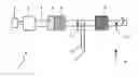
The test-bench of the present invention is schematically depicted in FIG. 1. The test set-up (1) comprises an engine (3), connected to an engine brake (2). The engine may be any commercially available or newly developed model, which provides for realistic process conditions. By combining the engine (3) with adjustable brake (2), specific working points (WP) can be chosen, i.e. a combination of a specific torque (Nm) at a certain engine speed (RPM). The engine off-gases are fed trough outlet (4) into a bed of oxidation catalyst (5), which is optional. Subsequently the gases are fed trough soot filter (6), which is also optional. At a measurement point labeled “pre-SCR” (7) various process conditions can be measured, such as concentrations of the relevant gases (NO, NO2, NH3, etc.), temperature, total pressure and the like. One of the specific features of the apparatus of the present invention is that it uses a combination of NH3 injection (8) and urea injection (9). This allows for measurements from which data can be derived that can be used to gain knowledge of the urea decomposition mechanism. Urea is used in real life deNOx facilities as a source of NH3. NH3 itself is generally too dangerous to handle in realistic deNOx applications, whereas urea is much more easy to handle. Because NH3 plays an important role in the reaction mechanisms that are at the basis of the model, the option to switch between urea and NH3 in accordance with the present invention results in very reliable results.
After the gases are contacted with urea and/or NH3, they are fed to SCR catalyst (10), where the actual deNOx reaction takes place.
After the gases leave the catalyst they are analyzed again at a measurement point labeled “post-SCR” (11). Also ambient conditions are monitored (temperature, pressure) at measurement point labeled “ambient measurement” (12).
The set-up of the present invention provides much more realistic results than fitting the equation on a flow bench with idealized circumstances (e.g. synthetic, simulated off-gases).
Following the procedure of the present invention, it is possible to make a first estimate of the SCR model parameters by fitting the parameters individually. This is possible because of special measurements that simplify and isolate reactions in the SCR model. The set of parameters determined via this method are used as a starting point for a global optimization of the model parameters. It was found that this is a far better approach than directly fitting all parameters with a global optimization. When starting with a random model parameter-set, the risk is big that the global optimization gives an unrealistic parameter-set.
Hereinbelow, first the test set-up that is required to perform the tests and the signals that should be measured during the tests are described. Then the tests to characterize the catalyst are described. Next the procedure to find the SCR catalyst parameters is detailed.
Test Setup and Measured Signals
A catalyst model can be fitted and validated by performing specific measurements on the SCR catalyst. In the prior art, these measurements are often performed with a flow reactor. According to the present invention the test method is carried out on an engine testbench (and possibly even on a chassis dynometer). The engine is a real life engine or similar thereto in its operation variables (in particular temperature development and off-gas composition).
The engine is connected to an engine brake. This can be a steady state or a transient brake. In accordance with the present invention, the exhaust line minimally contains a SCR catalyst and can contain a pre-oxidation catalyst and soot filter. Catalysts behind the SCR catalysts can be installed to set a back pressure.
SCR catalyst usually contain two catalyst modules, usually in the form of a well-known monolith (“honeycomb structure”) with parallel channels (herein referred to as “bricks”). In accordance with the present invention, one brick should be used for characterization. This gives more information on the conversion potential of the SCR catalyst.
Before the SCR catalyst a NH3 and urea solution (usually AdBlue™) injection point should be installed. It is important that the NH3 and urea (e.g. AdBlue) is homogeneously distributed in radial direction before it enters the SCR catalyst, which can be secured using common distributor means. For the urea injection it is important that the urea has enough residence time for the thermolysis process.
In one embodiment of the present invention the following signals are measured during the characterization of the SCR catalyst (see Table 2). An “X” means the corresponding signal is measured at the indicated point.
| TABLE 2 |
| Measured signals on test set-up |
| Measurement | Measurement | Measurement | |
| Measured | point pre SCR | point post SCR | point ambient |
| Pressure gas | X | X | X |
| Temperature gas | X | X | X |
| Exhaust mass-flow | X | ||
| CO | X | X | |
| Hydrocarbon | X | X | |
| CO2 | X | X | |
| O2 | X | X | |
| NOx | X | X | |
| NO | X | X | |
| N2O | X | X | |
| NH3 | X | ||
Test Program SCR Catalyst Characterization
To characterize the SCR catalyst system certain tests should be performed with the test set-up. Tests can be performed with NH3 injection and with urea (e.g. AdBlue) injection. Also if an oxidation catalyst is used pre SCR, the system can be tested with and without SCR catalyst. The measurements that can be performed are summarized in Table 3.
| TABLE 3 |
| Test program |
| Injection | SCR | Oxidation catalyst | Test |
| NH3 | — | X | validation of test set-up |
| urea (e.g. | — | X | validation of test set-up, |
| AdBlue) | thermolysis | ||
| NH3 | X | X | initial characterisation, |
| characterisation sequence | |||
| NH3 | X | initial characterisation, | |
| characterisation sequence | |||
| Urea (e.g. | X | X | characterisation sequence, |
| AdBlue) | driving cycle | ||
Validation of Test Set-Up and Thermolysis Measurements
The first step is to do measurements with the test set-up without the SCR catalyst. This means that the exhaustline is used as shown in FIG. 1, but without the SCR catalyst. With this set-up the equipment can be validated by performing specific tests. Also the thermolysis before the SCR catalyst can be characterized by performing measurements without SCR catalyst.
This part of the test-procedure typically comprises the following steps:
-
- Test communication
- Determine low temperature engine working point (for example 200° C.) with a maximum Space Velocity
- Determine reference engine working point (for example 300° C.) with a maximum Space Velocity
- Determine regeneration working point
With the following measurements the test set-up can be validated:
-
- Compare analyzers before and after the SCR catalyst
- Inject NH3 and check if it corresponds with value on NH3 analyzer
- Low temperature point
- Reference point
- Regeneration point
- Check cross sensitivity analyzers for NH3 by switching NH3 injection on/off in reference point
- Check if NH3 analyzer is working properly when making a transient from low temperature working point to the regeneration point
- Determine time delay between analyzers while making a transient from the reference point to the regeneration point
After that the thermolysis measurements are also performed without the SCR catalyst:
-
- Measure thermolysis in exhaustline at low temperature, reference and regeneration point with stoichiometric urea injection.
After these measurements the SCR catalyst can be installed.
With the SCR catalyst installed the following initial measurements are used to validate the system:
Steady State
-
- Inject NH3 (NSR=1; NSR is the normal stoichiometric ratio. This term is used to describe the NH3/NOx molar ratio of the reagent injected to uncontrolled NOx concentrations. If one mole of anhydrous ammonia is injected for each mole of NOx in the flue gas, the NSR is one, as one mole of ammonia will react with one mole of NOx. If one mole of urea is injected into the flue gas for each mole of NOx, the NSR is two. This is because one mole of urea will react with two moles of NOx. For both reagents, the higher the NSR, the greater the level of NOx reduction. Increasing NSR beyond a certain point, however, will have a diminishing effect on NOx reduction, with reagent utilization decreasing beyond this point) in reference point and check mass balance
- Inject urea (e.g. AdBlue) (NSR=1) in reference point and check mass balance
Transient
-
- Switch NH3 injection on (NSR=1) and off in reference point
- Switch urea (e.g. AdBlue) injection on (NSR=1) and off in reference point
Initial Characterization SCR Catalyst
With this part of the procedure an initial estimate of the model parameters can be determined. This is realized with a specific measurement program, that simplifies the model and isolates specific reactions.
For the initial parameter estimate procedure the assumption was made that the NOx conversion will remain constant when the NSR is increased above a certain value. This must be verified by running a test in which the NSR is increased in steps while the SCR catalyst temperature and Space Velocity remain constant (see FIG. 2).
The test should be realized in the low temperature point and reference point.
The test procedure for determining the relation between NH3 storage and NOx conversion is shown schematically in FIG. 2. The test begins with a high temperature working point to regenerate a soot filter if present, but also to remove absorbed emissions as hydrocarbons in the SCR catalyst. After this a constant working point is run. During this steady state operation of the engine the NH3 injection is switched on and off. For determining the intervals it is important that the intervals are long enough for reaching steady state conditions. The NH3 injection starts with high values and is reduced with small steps to finally reach no injection. This test is performed in the low temperature point and the reference point.
If the NOx conversion saturates at the high NSR values, the fit can be performed using the measurements from FIG. 2.
r NO = k NO exp ( - E NO RT ) · ( 1 - exp ( - θ NH 3 θ NH 3 * ) ) ( Equation 1 )
An example of the fit with θ*NH3 is given in FIG. 3, which shows a fit of θ*NH3 based on NH3 storage measurements.
If the NOx conversion is not saturating, the NSR values where the NOx conversion starts to decrease should not be used for the fit. The NSR values used in the experiments described in this document should be limited accordingly.
To characterize the catalyst, the catalyst performance should be measured at different temperatures and space velocities (SV). These different temperatures and SVs are realized by running the engine on the testbench in different working points. In accordance with the present invention a minimum number of working points is required, from which a maximum amount of information can be obtained. Preferably at least thirteen working points are used. Minimizing the number of working points results in considerably less experimentation time and consequently may save costs. When choosing the working points the following considerations are important:
The working points should be chosen such that a desired SCR catalyst temperature and SV are obtained. At the light-off temperature of the SCR catalyst extra working points should be chosen in temperature and SV direction. FIG. 4 schematically depicts engine working points based on SV and Tcatalyst. The working points should be tuned for a specific SCR catalyst. This should be done based on the NOx conversion potential in a working point. The NOx conversion potential is measured by injecting a NH3 quantity resulting in ±30 ppm NH3 slip. In accordance with the present invention the working points should have about the following NOx conversion (see Table 4).
| TABLE 4 |
| Indication NOx conversion for each working point |
| WP | indication NOx conversion (in %) | |
| 1 | 30 | |
| 2 | 0 | |
| 3 | 80 | |
| 4 | 30 | |
| 5 | 80 | |
| 6 | 30 | |
| 7 | 80 | |
| 8 | 30 | |
| 9 | <90 | |
| 10 | 50 | |
| 11 | 70 | |
| 12 | <90 | |
| 13 | <90 | |
Preferably certain working points should have the same SCR temperature and a variation in the Space Velocity: WP1 and 2, WP3 and 4, WP 5 and 6, WP7 and 8, WP9 and 10. By changing the Space Velocity, the NO2/NO ratio oxidation catalyst out changes (when an oxidation catalyst is used and placed before the SCR catalyst). Preferably the high Space Velocity working points (WP2, 4, 6, 10) should have a NO2/NO ratio below 1 and the low Space Velocity working points (WP1, 3, 5, 7) should have a NO2/NO ratio higher than 1.
If NOx conversion is not equal to desired value in a certain working point, the engine speed and/or torque should be changed to get the right NOx conversion.
The working points determined above are used for the tests in the remainder of the present application. An initial estimate of the NH3 adsorption/desorption parameters is made using the test shown schematically in FIG. 5, which shows a test sequence that can be used to get first estimate of storage and adsorption/desorption parameters. The test starts with a regeneration. After that the engine switches between two working points. A high and a low temperature working point. During the working point NH3 injection is switched on and off. The dosing of the NH3 injection is set too a high value, in order to simplify model parameterization.
The interval of the working points and NH3 injection should be chosen long enough to realize steady state conditions. The first part of the test is to fit the relative difference between adsorption/desorption parameters. With the second test and the result from the first test, the individual adsorption/desorption parameters can be fitted.
The following sequences can be run:
In the first sequence the following working points are used:
WP13 (NSR=2); WP2 (NSR=6); WP9 (NSR=3.5); WP2 (NSR=2); WP9 (NSR=2); WP2 (NSR=1.5); WP9); WP2 (NSR=1.2); and WP9
In the second sequence the following working points are used:
WP13 (NSR=2); WP4 (NSR=6); WP7 (NSR=3.5); WP4 (NSR=2); WP7 (NSR=2); WP4 (NSR=1.5); WP7); WP4 (NSR=1.2); and WP7.
When using the high NSR values as used in the tests, the assumption can be made that ra=rd and therefore that the NH3 that is used to convert NOx is negligible. The equation that should be solved is therefore (see Equation 2).
r a = r d ⇒ θ NH 3 = f ( k a 0 k d 0 , E a - E d ) ( Equation 2 )
An example of the fit of the parameters
( k a 0 k d 0 , E a - E d )
is shown in FIG. 6. The measured points (the crosses in FIG. 6) are a result from the first part of the test shown in FIG. 5.
With the second part of the measurements in FIG. 5 and the parameters ka/kd, Ea-Ed, the individual parameters can be determined. An example of this fit is shown in FIG. 7.
The NOx conversion parameters are fitted with a different test sequence. The test sequence comprises a series of working points. The characterization test sequence for SCR catalyst with high NSR is shown schematically in FIG. 8. The sequence of the working points is: WP13 (NSR=1.5); WP1 (NSR=2); WP5 (NSR=1.5); WP11 (NSR=1.5); WP3 (NSR=1.5);
WP12 (NSR=2); WP7 (NSR=2); WP4 (NSR=1.5); WP8 (NSR=1.5); WP6); and WP10 (NSR=1.5).
During the operation in a working point, NH3 is injected with a high NSR value. The high dosing should guarantee a homogeneous NOx conversion distribution through the length of the SCR catalyst. This simplifies the fitting of the NOx conversion parameters The duration of each working point should be chosen long enough to reach steady state conditions. Especially at low temperatures this can take significant time.
With the test a first estimate of the NOx conversion parameters can be made (kNO2, ENO2, kNO, ENO, kla, Ela).
In order to fit the six parameters in the three NOx reaction equations (see below) enough variation in the NO/NO2 ratio at the inlet of the SCR catalyst is required.
2NH3+NO+NO2→2N2+3H2O(T>200° C.)
4NH3+4NO+O2→4N2+6H2O(T>300° C., NO:NO2>1)
8NH3+6NO2→7N2+12H2O(T>400° C., NO:NO2<1, SV<100 000 h−1)
Optimization Fit SCR Catalyst
With the previous measurements an initial fit of the model parameters can be made. This is realized by isolating and fitting individual parameters. The fit of the model can be improved by optimizing the parameterset for more realistic NH3 injection quantities. For this the following test sequence is used (see FIG. 9, showing the test sequence for SCR catalyst with realistic NSR). This test sequence was also used for finding the initial NOx conversion parameters. During this test however more realistic NSR values are used. The NSR values used should result in a NH3 slip of about 30 ppm in each working point. Finally, the decomposition reaction parameters in the SCR catalyst can be fitted. This can be realized by repeating the test sequence as in FIG. 9, but now with AdBlue injection. The decomposition reaction parameters can be fitted indirectly by comparing the NOx conversion and NH3 slip over the test between NH3 and AdBlue injection.
The parameter fitting process of the present invention provides for the possibility of limiting the amount of time and costs involved for SCR catalyst model developing. The method of the invention can be conveniently automated and presented in the form of a software tool.
Claims
1. Apparatus for carrying out an SCR catalyst system calibration method comprising an engine (3), operable connected to an adjustable engine brake (2), which engine is connected to outlet (4) for off-gas, which outlet (4) is optionally connected to an oxidation catalyst (5), which is optionally connected to a soot filter (6), further comprising a pre-SCR measurement point (7), a NH3 injection point (8) and a urea injection point (9), an SCR catalyst (10), a measurement point labeled “post-SCR” (11) and a measurement point labeled “ambient measurement” (12).
2. Process for fitting parameters in a SCR catalyst model, comprising the steps of operating the apparatus of claim 1, comprising operating said engine (3), whereby an NOx-comprising offgas is produced, and carrying out at least two different measurements on said offgas, the first measurement being determining the NOx-conversion by said SCR catalyst (10) using NH3 from said NH3 injection point (8) and the second measurement being determining the NOx-conversion by said SCR catalyst (10) using urea from said urea injection point (9) and using said measurement in said fitting of parameters.
3. Process according to claim 2, comprising the steps of:
determining at least two working points;
determining the relation between NH3 storage and NOx conversion carrying out saturation measurements;
running tests using high NH3 injection;
running tests with normal NH3 injection; and
running tests with normal urea injection.
Images & Drawings included:


Sources:
- United States Patent and Trademark Office - verify current appl. status at the USPTO↗
Recent applications in this class:
- » 20250041802 2025-02-06
CONTROLLER AND METHOD FOR CONFIGURING PUMP AND DOSER OF AFTERTREATMENT SYSTEM - » 20230182074 2023-06-15
Reducer supply device - » 20230037326 2023-02-09
Method for adaption of an exhaust treatment system - » 20190232225 2019-08-01
Exhaust emission control device, method and computer program product for an engine - » 20180028976 2018-02-01
Reagent doser diagnostic system and method - » 20180028975 2018-02-01
EXHAUST GAS PURIFICATION SYSTEM FOR INTERNAL COMBUSTION ENGINE, INTERNAL COMBUSTION ENGINE, AND EXHAUST GAS PURIFICATION METHOD FOR INTERNAL COMBUSTION ENGINE - » 20180028974 2018-02-01
Systems and method for feed forward control of diesel exhaust fluid delivery systems - » 20180015412 2018-01-18
Exhaust gas purification system, and NOx purification capacity restoration method - » 20180008932 2018-01-11
DEF DOSING FOR SELECTIVE CATALYTIC REDUCTION CATALYSTS - » 20170333844 2017-11-23
Method and system for mitigating urea deposits within an SCR catalyst system
Recent applications for this Assignee:
- » 20170099515 2017-04-06
Fingerprint-based inter-destination media synchronization - » 20160365973 2016-12-15
Secure Distribution of Watermarked Content - » 20160030516 2016-02-04
PREVENTION, THERAPY AND PROGNOSIS/MONITORING IN SEPSIS AND SEPTIC SHOCK - » 20160010954 2016-01-14
Protective armour element - » 20150373621 2015-12-24
Method and telecommunications infrastructure enabling localized time controlled access for a device - » 20150323561 2015-11-12
High throughput microscopy device - » 20150293145 2015-10-15
Calibration of a mechanical property of SPM cantilevers - » 20150274849 2015-10-01
Resistant starch - » 20150226622 2015-08-13
Pressure sensing assembly - » 20150201654 2015-07-23
Hydrothermally modified starch