Cone type venturi integrated valve device
US20110041622A1
2011-02-24
12/734,701
2010-01-20
✅ Patent granted
US 8,434,373 B2
2013-05-07
WO; PCT/KR2010/000364; 20100120
WO; WO2010/085084; 20100729
Harshad R Patel
Wenderoth, Lind & Ponack, L.L.P.
2030-08-10
Abstract:
Provided is a valve device into which a cone type venturi for a flow measurement and valves are integrated. According to the present invention, the venturi cone is formed in venturi path in the lower portion of the main body, and then valve path is formed thereafter. According to the present invention, efforts for adjusting heights between both of pressure taps during connecting of valves and flow measurement parts are not required and installation time and costs of installation could be decreased drastically. Also, the possibilities of leakage as well as manufacturing costs also could be reduced by integrating valves and flow measurement parts into a one-body valve device.
Inventors:
- Bong Ku Kim 12 🇰🇷 Seoul, South Korea
- Philip Lawrence Andrew 1 🇺🇸 Houston, TX, United States
- Jin-Ho Seol 1 🇰🇷 Seoul, South Korea
- Yong-Ha Kim 2 🇰🇷 Seoul, South Korea
- Philip Andrew Lawrence 1 🇺🇸 Houston, TX, United States
Assignee:
- CAMERON INTERNATIONAL CORPORATION 1,133 🇺🇸 Houston, TX, United States
- Hitrol Co., Ltd 1 🇰🇷 Gyeonggi-Do, South Korea
Applicant:
Interested in similar patents?
Get notified when new applications in this technology area are published.
Classification:
F16K27/003 » CPC main
Construction of housing ; Use of materials therefor Housing formed from a plurality of the same valve elements
F16K11/22 » CPC further
Multiple-way valves, e.g. mixing valves; Pipe fittings incorporating such valves with two or more closure members not moving as a unit operated by separate actuating members with an actuating member for each valve, e.g. interconnected to form multiple-way valves
G01F1/40 » CPC further
Measuring the volume flow or mass flow of fluid or fluent solid material wherein the fluid passes through a meter in a continuous flow by using mechanical effects by measuring pressure or differential pressure the pressure or differential pressure being created by the use of flow constriction Details of construction of the flow constriction devices
G01F15/005 » CPC further
Details of, or accessories for, apparatus of groups - insofar as such details or appliances are not adapted to particular types of such apparatus Valves
G01F1/44 IPC
Measuring the volume flow or mass flow of fluid or fluent solid material wherein the fluid passes through a meter in a continuous flow by using mechanical effects by measuring pressure or differential pressure the pressure or differential pressure being created by the use of flow constriction; Details of construction of the flow constriction devices Venturi tubes
Description
TECHNICAL FIELD
The present invention relates to the valve device, and more particularly relates to the valve device into which a cone type venturi for flow measurement is integrated.
BACKGROUND ART
In general, venturi cones are widely used for measuring of flows using differential pressure between an inlet and an outlet. And, the valve is installed together with cone type venturi.
DISCLOSURE OF INVENTION
Technical Problem
However, according to the conventional way, fluid leakage could be happened from connecting part between the flow measurement part and the valves, and as one of the installation requirements, adjusting heights between both of pressure taps during connecting of valves and flow measurement parts is required. However, the adjusting process is quite cumbersome and takes long time. Also, the conventional valve device has a disadvantage in that bending of pipes could be happened due to the over-heating produced during welding process of two pieces of nipples and one piece of cone support rod for installation.
Solution to Problem
The present invention provides a cone type venturi integrated valve device for flow measurement, which is formed by integrating valves and cone type venturi into a one-body valve device. According to the present invention, efforts for adjusting heights between both of pressure taps during connecting of valves and flow measurement parts are not required and concern of leakage and thus installation costs could be reduced as well.
Advantageous Effects of Invention
According to the present invention, efforts for adjusting heights between both of pressure taps during connecting of valves and flow measurement parts are not required and thereby installation time and cost of installation are drastically decreased as well. Also, the possibility of leakage and manufacturing costs are reduced by integrating valves and flow measurement parts into a one-body valve device.
BRIEF DESCRIPTION OF DRAWINGS
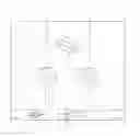
FIG. 1 shows a valve device for flow measurement in which cone type venturi is integrated according to an embodiment of the present invention. Reffering to FIG. 1.
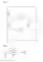
FIG. 2 shows a diagram for showing how to install the venturi cone to the main body.
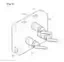
FIG. 3. shows a valve device for flow measurement in which cone type venturi is integrated according to an embodiment of the present invention.
BEST MODE FOR CARRYING OUT THE INVENTION
The present invention will now be described more fully with reference to the accompanying drawings, in which exemplary embodiments of the invention are shown.
FIG. 1 shows a valve device for flow measurement in which cone type venturi is integrated according to an embodiment of the present invention. Reffering to FIG. 1, the valve device for flow measurement in which cone type venturi is integrated according to an embodiment of the present invention comprises a main body 10 constructed of stainless steel; Venturi path 12 for passing-by fluid which is formed in the main body 10 by penetrating through the main body 10 in a horizontal direction; Venturi cone 14 which is mounted between the first pressure point P1 and the second pressure point P2 in the venturi path 12, and wherein the venturi cone 14 acts to make the pressure of fluid at the second pressure point P2 relatively lower than that of first pressure point P1; and valve path 16.
The venturi path 12 comprises a hole 120 where is penetrated at below. In this venturi path 12, a point of certain distance from the inlet side is defined as the first pressure point and the other point of certain distance from the outlet side is defined as the second pressure point P2.
The venturi cone 14 is mounted between the first pressure point P1 and the second pressure point P2 in the venturi path 12. Also, the venturi cone 14 comprises a first cone body 144 having a mild slope surface 142 faced to the first pressure point P1, a second cone body 148 having a steep slope surface 142 faced to the second pressure point P2, and a fixing leg 154 extending(150) from the cone end of the first cone body 144 to the direction of center axis for a predetermined length. The fixing leg 154 is bent(152) toward bottom, and bent end is inserted into the hole 120 of the venturi path 12, and the bent end is attached by welding process at the bottom. The venturi cone 14 acts to make the pressure of fluid at the second pressure point P2 relatively lower than that of first pressure point P1.
The valve path 16 comprises fluid paths which is formed by penetrating hole in a vertical direction with respect to the venturi path 12, and then the valve path 16 is connected with the first pressure point P1 and the second pressure point P2. Also the valve path 16 comprises valves 162 for switching of fluid flowing through the fluid paths.
When the cone type venturi is formed after valve path 16 has been established, packing portion composed with PTFE(Poly Tetra Fluoro-Ethylene) which is called with Teflon™ or synthetic polymer polyamide which is called with Nylon™ could be damaged by the heat provided during welding process of venturi cone. Therefore, it is preferred to form the valve path 16 after welding process of venturi cone 14 has been done.
Also, it is preferred that, in the first cone body 144 and the second cone body 148, a center hole 149 extending from its cone end in its center axis direction.
FIG. 2 shows a diagram for showing how to install the venturi cone to the main body. Reffering to FIG. 2, when the venturi cone is installed between the first pressure point P1 and the second pressure point P2 in the venturi path 12, a centering jig 20 is used for adjusting the position of the first cone body 144 and the second cone body 148 to the center of fluid path accurately.
The centering jig 20 has a center projection 202 protruding toward outside. The center projection 202 fits the center hole 149 of the second cone body 148.
FIG. 3. shows a valve device for flow measurement in which cone type venturi is integrated according to an embodiment of the present invention. Reffering to FIG. 3, the valve device comprises a main body 30, and a venturi path formed in the lower portion of the main body 30. Inlet of a venturi path corresponds to inlet port 302. The valves 304 are mounted in the valve path which is connected to the venturi path. Outlet of a venturi path corresponds to sensor port 306.
According to the present invention, the venturi cone is formed in venturi path in the lower portion of the main body, and then valve paths are formed by processing, so that efforts for adjusting heights between both of pressure taps during connecting of valves and flow measurement parts are not required and installation time and cost of installation are drastically decreased. Also, the possibility of leakage as well as manufacturing costs are also reduced by integrating valves and flow measurement parts into a one-body valve device.
Claims
1. A cone type venturi integrated valve device comprising,
a main body 10 constructed of stainless steel;
a venturi path 12 which is formed in the main body 10 by penetrating in a horizontal direction, and including a hole 120 toward bottom, wherein a point of certain distance from the inlet side is defined as the first pressure point and the other point of certain distance from the outlet side is defined as the second pressure point P2;
a venturi cone 14 which is mounted between the first pressure point P1 and the second pressure point P2 in the venturi path 12, and including a first cone body 144 having a mild slope surface 142 faced to the first pressure point P1 and a second cone body 148 having a steep slope surface 142 faced to the second pressure point P2, and a fixing leg 154 extending (150) from the cone end of the first cone body 144 to the direction of center axis for a predetermined length, wherein the fixing leg 154 is bent(152) toward below and the bent end is inserted into the hole 120 of the venturi path 12 and attached by welding process, and wherein the venturi cone 14 acts to make the pressure of fluid at the second pressure point P2 relatively lower than that of first pressure point P1; and
a valve path 16 which is formed by penetrating through the main body 10 in a vertical direction with respect to the venturi path 12 so that the valve path 16 is connected with the first pressure point P1 and the second pressure point P2 of the venturi path 12, and including valves 162 for switching of fluid flowing through the valve path.
2. The cone type venturi integrated valve device of claim 1, wherein the second cone body 148 further comprises:
a center hole 149 extending from its cone end to its center axis direction.
Images & Drawings included:
Sources:
- United States Patent and Trademark Office - verify current appl. status at the USPTO↗
Recent applications in this class:
- » 20250207679 2025-06-26
GAS DELIVERY SYSTEM - » 20250207678 2025-06-26
VALVE ARRANGEMENT - » 20250122946 2025-04-17
VALVE ASSEMBLY AND MOUNTING PLATE COMPRISING A VALVAE ASSEMBLY - » 20250035227 2025-01-30
FLUID DELIVERY MOUNTING PANEL AND SYSTEM - » 20250020230 2025-01-16
Rotating Valve System - » 20250003513 2025-01-02
MODULARLY STRUCTURED VALVE ARRANGEMENT FOR A HOUSING - » 20240426390 2024-12-26
ELECTRICALLY ACTUATED VALVES - » 20240209952 2024-06-27
Valve Device, Valve Housing and Universal Valve Housing - » 20240167578 2024-05-23
MODULAR MANIFOLD FOR USE WITH A MICROFLUIDICS CHIP AND HAVING TWO-WAY AND THREE-WAY PLATE MANIFOLDS AND METHOD OF MAKING THE SAME - » 20240142014 2024-05-02
SYSTEMS AND APPARATUS FOR A VALVE MANIFOLD
Recent applications for this Assignee:
- » 20240418693 2024-12-19
Method and apparatus for methane management - » 20240360907 2024-10-31
BALL VALVE ASSEMBLY - » 20240309926 2024-09-19
SYSTEM AND METHOD FOR DAMPING FORCES EXERTED ON A CABLE - » 20240271591 2024-08-15
GENERATOR SYSTEM FOR RESOURCE EXTRACTION AND INJECTION SYSTEM - » 20240247729 2024-07-25
Hard and lubricious valve surfaces, material compositions and sequences of manufacturing - » 20240229588 2024-07-11
Wellhead assembly monitoring sensor and method - » 20240125194 2024-04-18
Hanger systems and methods - » 20240109829 2024-04-04
System and process for removal of organic carboxylates from mono ethylene glycol (MEG) water streams by acidification and vaporization under vacuum - » 20240044236 2024-02-08
System and method for valve greasing in a well tree - » 20240011383 2024-01-11
Apparatus and method of disbursing materials into a wellbore