Zero-pitch pipe
US20110048561A1
2011-03-03
12/585,072
2009-09-02
Abstract:
A pipe is provided through which a fluid can move without backflow in the absence of a gravity force provided by a downward pitch. This is accomplished by providing within the pipe a series of one-way valves, each having a structure similar to a mitral valve, with a rigid upper flap cooperating with a semi-rigid but flexible lower flap. Fluid pressure upstream of the valve will displace the lower flap enough to allow fluid to accumulate in a reservoir area downstream of the valve and upstream of a ramp structure. When sufficient fluid accumulates in the reservoir area, it overflows the ramp structure and proceeds to the next one-way valve, and the process is repeated.
Interested in similar patents?
Get notified when new applications in this technology area are published.
Classification:
F16K15/144 » CPC main
Check valves with flexible valve members the closure elements being fixed along all or a part of their periphery
F16K7/07 » CPC further
Diaphragm cut-off apparatus, e.g. with a member deformed, but not moved bodily, to close the passage with tubular diaphragm constrictable by external radial force by means of fluid pressure
A61F2/2412 » CPC further
Filters implantable into blood vessels; Prostheses, i.e. artificial substitutes or replacements for parts of the body; Appliances for connecting them with the body; Devices providing patency to, or preventing collapsing of, tubular structures of the body, e.g. stents; Prostheses implantable into the body; Heart valves ; Vascular valves, e.g. venous valves; Heart implants, e.g. passive devices for improving the function of the native valve or the heart muscle; Transmyocardial revascularisation [TMR] devices; Valves implantable in the body with soft flexible valve members, e.g. tissue valves shaped like natural valves
Y10T137/88054 » CPC further
Fluid handling; Systems; Flow path with serial valves and/or closures Direct response normally closed valve limits direction of flow
F16K1/32 IPC
Lift valves or globe valves , i.e. cut-off apparatus with closure members having at least a component of their opening and closing motion perpendicular to the closing faces Details
Description
BACKGROUND OF THE INVENTION
The present invention relates to the field of pipes for conveying fluids, and more particularly to a type of pipe through which a fluid will flow without the force of gravity, as when a pipe is installed with no downward pitch.
The present invention comprises a pipe through which a fluid can move without backflow in the absence of a gravity force provided by a downward pitch. This is accomplished by providing within the pipe a series of one-way valves each having a structure similar to a mitral valve, with a rigid upper flap cooperating with a semi-rigid but flexible lower flap. Fluid pressure upstream of the valve will displace the lower flap enough to allow fluid to accumulate in a reservoir area downstream of the valve and upstream of a ramp structure. When sufficient fluid accumulates in the reservoir area, it overflows the ramp structure and proceeds to the next one-way valve, and the process is repeated.
U.S. Pat. No. 4,989,760 to Songzeng, describes a self-filling siphon pipe which comprises a series of internal one-way valves. But the Songzeng device relies on the suction force from a siphon hose to move liquid through the pipe, whereas the present invention requires no fluid transport force beyond the passive fluid pressure in the pipe.
U.S. Pat. No. 3,855,995 to Bentley describes a blood pumping assembly in which a series of leaflet-type valves are used in conjunction with a ramp-like structure to provide passive flow of blood through the device. But the valve structure is dissimilar to the present invention insofar as it lacks the asymmetrical flexibility of the valve. Also, fluid movement through the assembly is ultimately dependent on the external force provided by a pump.
U.S. Pat. No. 6,089,260 to Jaworski et al. describes nested duckbill check valve system for back-flow prevention used in conduits such as garden hose nozzles. While this design has serial one-way check valves, it provides no mechanism for passive fluid flow and thus would not be applicable to a zero-pitch pipe.
SUMMARY OF THE INVENTION
The present invention comprises a tubular pipe fabricated of durable metal or plastic. Within the pipe are a series of one-way valves, with each valve comprising a rigid upper flap and a semi-rigid, flexible lower flap. The upper flap is preferably concave and the lower flap is preferably flat. The upper flap is rigidly attached to the upper interior surface of the pipe, while the lower flap is rigidly attached to the lower interior surface of the pipe.
Downstream of each one-way valve is a ramp structure that has a forward slope and a rear slope. The forward slope is less steeply inclined than the rear slope. The ramp structure is fabricated of rigid metal or plastic and is rigidly attached to the lower interior surface of the pipe.
When a fluid flow within the pipe encounters one of the one-way valves, the pressure of the fluid causes the valve's lower flap to bend downward, thus allowing the fluid to fill the back reservoir until it overflows the rear slope of the ramp structure and flows down the forward slope into the front reservoir.
The fluid accumulates in the front reservoir until the fluid pressure causes the lower flap of the next one-way valve to bend downward, and the flow process described above is repeated. In this way, a fluid can flow from one end of the pipe to the other without the aid of gravity.
Optionally, the one-way valves can be eliminated, such that the fluid flow through the pipe is controlled by the ramp structures alone.
BRIEF DESCRIPTION OF THE DRAWINGS
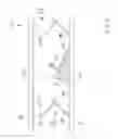
FIG. 1 is a longitudinal cross-section view of the preferred embodiment of the present invention.
FIG. 2 is a transverse cross-section view of the preferred embodiment of the present invention along the line 2-2 shown in FIG. 1.
DETAILED DESCRIPTION OF THE PREFERRED EMBODIMENT
Referring to FIGS. 1 and 2, the present invention 10 comprises a tubular pipe 11 fabricated of durable metal or plastic. Within the pipe 11 are a series of one-way valves 12, with each valve comprising a rigid upper flap 13 and a semi-rigid, flexible lower flap 14. The upper flap 13 is preferably concave and the lower flap 14 is preferably flat. The upper flap 13 is rigidly attached to the upper interior surface of the pipe 11, while the lower flap 14 is rigidly attached to the lower interior surface of the pipe 11.
Downstream of each one-way valve 12 is a ramp structure 15 that has a forward slope 16 and a rear slope 17. The forward slope 16 is less steeply inclined than the rear slope 17. The ramp structure 15 is fabricated of rigid metal or plastic and is rigidly attached to the lower interior surface of the pipe 11.
When a fluid flow 18 within the pipe 11 encounters one of the one-way valves 12, the pressure of the fluid 18 causes the valve's lower flap 14 to bend downward, thus allowing the fluid 18 to fill the back reservoir 19 until it overflows the rear slope 17 of the ramp structure 15 and flows down the forward slope 16 into the front reservoir 20.
The fluid 18 accumulates in the front reservoir 20 until the fluid pressure 18 causes the lower flap 14 of the next one-way valve 12 to bend downward, and the flow process described above is repeated. In this way, a fluid can flow from one end of the pipe 11 to the other without the aid of gravity.
Although the preferred embodiment of the present invention has been disclosed for illustrative purposes, those skilled in the art will appreciate that many additions, modifications and substitutions are possible, without departing from the scope and spirit of the present invention.
Claims
What is claimed is:1. A pipe comprising:
(a) a tubular wall enclosing an interior volume, which interior volume is transversely divisible into multiple circular cross-sections and longitudinally divisible into a semi-cylindrical upper volume and a semi-cylindrical lower volume;
(b) within the interior volume, a series of one-way valves, each valve extending across one of the cross-sections, and each valve comprising two overlapping, cooperating duck-billed or mitral valve flaps;
(c) between the valves, a series of ramp structures, each ramp structure extending within the lower volume across a portion of one of the cross-sections, and each ramp structure have an inclined rear slope facing a preceding valve and an inclined forward slope facing a succeeding valve;
(d) between each rear slope and each preceding valve, a back reservoir, containing a portion of the lower volume; and
(e) between each forward slope and each succeeding valve, a front reservoir, containing a portion of the lower volume.
2. The pipe according to claim 1, wherein one of the valve flaps is an upper flap extending within the upper volume across a portion of one of the cross-sections, and the other valve flap is a lower flap extending within the lower volume across a portion of one of the cross-sections.
3. The pipe according to claim 2, wherein the upper flap is rigid, while the lower flap is semi-rigid and capable of bending downward in the direction of the rear slope of the ramp structure, thereby creating an opening between the upper flap and lower flap through which a fluid can flow into the back reservoir.
4. The pipe according to claim 3, wherein the rear slope of each ramp structure is inclined more steeply than the forward slope.
5. A pipe comprising:
(a) a tubular wall enclosing an interior volume, which interior volume is transversely divisible into multiple circular cross-sections and longitudinally divisible into a semi-cylindrical upper volume and a semi-cylindrical lower volume;
(b) within the interior volume, a series of ramp structures, each ramp structure extending within the lower volume across a portion of one of the cross-sections, and each ramp structure have an inclined rear slope facing a preceding ramp structure and an inclined forward slope facing a succeeding ramp structure;
(c) between each rear slope and each preceding ramp structure, a back reservoir, containing a portion of the lower volume; and
(d) between each forward slope and each succeeding ramp structure, a front reservoir, containing a portion of the lower volume.
6. The pipe according to claim 5, wherein the rear slope of each ramp structure is inclined more steeply than the forward slope.
Images & Drawings included:


Sources:
- United States Patent and Trademark Office - verify current appl. status at the USPTO↗
Recent applications in this class:
- » 20230323970 2023-10-12
Valve - » 20230099255 2023-03-30
Color changing and pressure sensing check valves - » 20220333704 2022-10-20
Valve and application apparatus - » 20220099203 2022-03-31
Color changing and pressure sensing check valves - » 20220099202 2022-03-31
Fluid Unidirectional Flow Structure, Check Assembly, and Respiratory Device - » 20220018458 2022-01-20
Valve - » 20210172539 2021-06-10
Check valve element for a check valve assembly and corresponding check valve assembly - » 20200378509 2020-12-03
AIR VALVE FOR AN INFLATABLE DEVICE - » 20180306337 2018-10-25
Transmission control device - » 20180231136 2018-08-16
Airbox drain valve