Power cable
US20110048768A1
2011-03-03
12/736,683
2009-04-02
✅ Patent granted
US 8,618,413 B2
2013-12-31
WO; PCT/GB2009/050324; 20090402
WO; WO2009/133381; 20091105
William H Mayo, III
Faegre Baker Daniels LLP
2029-07-07
Abstract:
A power cable (10) is disclosed comprising a metal conductor encased in a first outer sheath (11), and further encased, partially along the length of the cable, in a second outer sheath (12, 13, 14) which influences the pattern of deformation of the cable under mechanical stress.
Inventors:
- Jonathan Catchpole 2 🇬🇧 Oxfordshire, United Kingdom
- David John Porter 2 🇬🇧 Wiltshire, United Kingdom
- Stewart Toplis 1 🇬🇧 Wiltshire, United Kingdom
Assignee:
- TYCO ELECTRONICS UK LTD 16 🇬🇧 Swindon Wiltshire, United Kingdom
- TYCO ELECTRONICS UK LTD 51 🇬🇧 Wiltshire, United Kingdom
Applicant:
Interested in similar patents?
Get notified when new applications in this technology area are published.
Classification:
H01B7/0216 » CPC main
Insulated conductors or cables characterised by their form; Disposition of insulation; Cables with several layers of insulating material Two layers
H01B7/24 » CPC further
Insulated conductors or cables characterised by their form; Protection against damage caused by external factors, e.g. sheaths or armouring by wear, mechanical force or pressure Devices affording localised protection against mechanical force or pressure
H01B7/08 » CPC further
Insulated conductors or cables characterised by their form Flat or ribbon cables
H01B7/18 IPC
Insulated conductors or cables characterised by their form; Protection against damage caused by external factors, e.g. sheaths or armouring by wear, mechanical force or pressure
H01B7/00 IPC
Insulated conductors or cables characterised by their form
Description
FIELD OF INVENTION
This invention relates to a power cable.
SUMMARY OF INVENTION
In accordance with the present invention, there is provided a power cable comprising a metal conductor encased in a first outer sheath, and further encased, partially along the length of the cable, in a second outer sheath which influences the pattern of deformation of the cable under mechanical stress.
The first and second outer sheaths may be heat shrink tubing.
The second outer sheath may be located in the middle of the cable, at both ends of the cable or, in three distinct sections, in the middle and at both ends of the cable.
BRIEF DESCRIPTION OF DRAWINGS
The invention will now be described, by way of example only, with reference to the following figures in which:
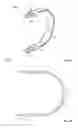
FIGS. 1a and 1b are 3-D and plan views respectively of a high voltage, high power jumper cable according to the present invention.
DETAILED DESCRIPTION
Referring to FIGS. 1a and 1b, a jumper cable 10 is shown comprising two terminals 15, 16 connected by a conducting tin coated, copper braid (not shown) which is entirely encases in a first layer of heat shrink tubing 11.
In accordance with the present invention, a second layer of heat shrink tubing 12, 13, 14 is applied over the first layer of heat shrink tubing in three locations; a first part 12 at the centre of the conducting cable, and second 13 and third 14 parts adjacent the terminals 15, 16.
In use, the second layer of heat shrink tubing 12, 13, 14 provides additional support of the conducting braid, and the selective application of the second layer of heat shrink tubing on the first layer of heat shrink tubing 11 influences the pattern of deformation of the cable 10 under mechanical. I.e. there is less deformation in such regions.
Although the embodiment description provides the second layer of heat shrink tubing 12, 13, 14 in three locations of the jumper cable 10, other configurations are contemplated.
Claims
1-6. (canceled)
7. A power cable comprising a metal conductor encased in a first outer sheath, and further encased, partially along the length of the cable, in a second outer sheath which influences the pattern of deformation of the cable under mechanical stress.
8. A cable according to claim 1, wherein the first outer sheath is heat shrink tubing.
9. A cable according to claim 1, wherein the second outer sheath is heat shrink tubing.
10. A cable according to claim 1, wherein the second outer sheath is located in the middle of the cable.
11. A cable according to claim 1, wherein the second outer sheath is located at both ends of the cable.
12. A cable according to claim 1, wherein the second outer sheath is located in three distinct sections in the middle and at both ends of the cable.
Images & Drawings included:

Sources:
- United States Patent and Trademark Office - verify current appl. status at the USPTO↗
Similar patent applications:
- » 20170271860
Power cable, power cable system, method of grounding power cable system and method of constructing power cable system - » 20250034381
INSULATING RESIN COMPOSITION FOR ELECTRIC POWER CABLE, ELECTRIC POWER CABLE, AND ELECTRIC POWER CABLE CONNECTING PART - » 20220157486
Insulating tape for coating connection portion of power cable, method for forming insulating coating on exterior surface of connection portion of power cable, and power cable - » 20190375925
Insulating resin composition for DC power cable, crosslinked resin body, DC power cable, member for forming reinforcing insulating layer of DC power joint, and DC power cable joint - » 20230340946
Self-clamping cable guard for clamping power cables of a power cable bundle of a cable support arrangement in a wind turbine, cable support arrangement and wind turbine - » 20190348199
Process for manufacturing a power cable and power cable obtainable thereof - » 20210082599
Process for manufacturing a submarine power cable and power cable so manufactured - » 20140076609
Insulation composition for DC power cable and DC power cable prepared by using the same - » 20160314869
A NEW CROSSLINKED LOW MFR POLYMER COMPOSITION, POWER CABLE INSULATION AND POWER CABLE - » 20160319104
Crosslinked polymer composition, power cable insulation and power cable
Recent applications in this class:
- » 20250201442 2025-06-19
INSULATED WIRE - » 20250140442 2025-05-01
RECTANGULAR WIRE, COIL, AND THERMAL SHRINKAGE TUBE - » 20250095877 2025-03-20
CABLE - » 20250079040 2025-03-06
RIBBON CABLE HAVING INDIVIDUALLY-INSULATED WIRES - » 20250069774 2025-02-27
MULTICORE CABLE - » 20240212877 2024-06-27
INSULATING PLUGS, HIGH-VOLTAGE CABLES AND X-RAY TUBES - » 20240153670 2024-05-09
Transmission line - » 20240021341 2024-01-18
CABLE - » 20230170109 2023-06-01
Cable with low mode conversion performance - » 20230114286 2023-04-13
Cable and cable assembly
Recent applications for this Assignee:
- » 20220220295 2022-07-14
Cross-Linkable Fluoropolymer Compositions - » 20220025148 2022-01-27
Shape memory products and method for making them - » 20210273350 2021-09-02
Insulation displacement contact and insulation displacement contact assembly for high performance electrical connections - » 20180362231 2018-12-20
Cable tie - » 20170324183 2017-11-09
Electrical contact device - » 20170244187 2017-08-24
Contact stud, terminal and contact assembly in particular for car technology - » 20170117644 2017-04-27
Split connector with circular dove tail - » 20170073514 2017-03-16
Polymer composition and heat-shrinkable article - » 20170062955 2017-03-02
Connector assembly with a blade connector - » 20170009040 2017-01-12
Shape Memory Products and Method For Making Them