Assembly for head welding
US20110049220A1
2011-03-03
12/991,078
2009-04-24
✅ Patent granted
US 8,459,528 B2
2013-06-11
WO; PCT/BG2009/000005; 20090424
WO; WO2009/140744; 20091126
Devang R Patel
Marshall, Gerstein & Borun LLP
2029-05-20
Abstract:
The assembly is intended for application to manufacturing of tubes, bottles, boxes. Characterized by improved quality of the weld and low reject percentage. It has a mandrel (1), on which there is a head (3) and a tube body (2), put over in a typical manner, as well as a cooling element, coaxial with the mandrel (1), and a nozzle D, coaxial with the mandrel. Said nozzle contains two parts—internal 7 and external (8)—which form channel (9) for feeding heating gas HG. The assembly consists of only one work station. The cooling element is also forming element OFE and consists of cooling metal ring 4, located in forming metal ring (6). There is heat-insulating ring (5) between the latter and the cooling metal ring (4). In the position of heating, said heat-insulating ring (5) is positioned around the end of the tube body (2). The heat-insulating ring (5) is of solid-state material or gas of low thermal conduction.
Applicant:
Interested in similar patents?
Get notified when new applications in this technology area are published.
Classification:
B65B31/02 IPC
Packaging articles or materials under special atmospheric or gaseous conditions; Adding propellants to aerosol containers Filling, closing, or filling and closing, containers or wrappers in chambers maintained under vacuum or superatmospheric pressure or containing a special atmosphere, e.g. of inert gas
B29B13/025 » CPC main
Conditioning or physical treatment of the material to be shaped by heating; Half-products, e.g. films, plates; Hollow bodies, e.g. tubes or profiles Tube ends
B29C65/10 » CPC further
Joining of preformed parts ; Apparatus therefor by heating, with or without pressure using hot gases (e.g. combustion gases) or flames coming in contact with at least one of the parts to be joined
B29C65/568 » CPC further
Joining of preformed parts ; Apparatus therefor using mechanical means or mechanical connections, e.g. form-fits using a tamping or a swaging operation, i.e. at least partially deforming the edge or the rim of a first part to be joined to clamp a second part to be joined using a swaging operation, i.e. totally deforming the edge or the rim of a first part to be joined to clamp a second part to be joined
B29C66/1222 » CPC further
General aspects of processes or apparatus for joining preformed parts; General aspects dealing with the joint area or with the area to be joined; Particular design of joint configurations particular design of the joint cross-sections; Joint cross-sections combining only two joint-segments; Tongue and groove joints; Tenon and mortise joints; Stepped joint cross-sections; Joint cross-sections combining only two joint-segments, i.e. one of the parts to be joined comprising only two joint-segments in the joint cross-section comprising at least a lapped joint-segment
B29C66/1226 » CPC further
General aspects of processes or apparatus for joining preformed parts; General aspects dealing with the joint area or with the area to be joined; Particular design of joint configurations particular design of the joint cross-sections; Joint cross-sections combining only two joint-segments; Tongue and groove joints; Tenon and mortise joints; Stepped joint cross-sections; Joint cross-sections combining only two joint-segments, i.e. one of the parts to be joined comprising only two joint-segments in the joint cross-section comprising at least one bevelled joint-segment
B29C66/1312 » CPC further
General aspects of processes or apparatus for joining preformed parts; General aspects dealing with the joint area or with the area to be joined; Particular design of joint configurations particular design of the joint cross-sections; Single flanged joints; Fin-type joints; Single hem joints; Edge joints; Interpenetrating fingered joints; Other specific particular designs of joint cross-sections not provided for in groups - ; Single flanged joints, i.e. one of the parts to be joined being rigid and flanged in the joint area Single flange to flange joints, the parts to be joined being rigid
B29C66/348 » CPC further
General aspects of processes or apparatus for joining preformed parts; General aspects dealing with the joint area or with the area to be joined Avoiding melting or weakening of the zone directly next to the joint area, e.g. by cooling
B29C66/5344 » CPC further
General aspects of processes or apparatus for joining preformed parts; General aspects of joining tubular articles; General aspects of joining long products, i.e. bars or profiled elements; General aspects of joining single elements to tubular articles, hollow articles or bars; General aspects of joining several hollow-preforms to form hollow or tubular articles; Joining tubular articles, profiled elements or bars; Joining single elements to tubular articles, hollow articles or bars; Joining several hollow-preforms to form hollow or tubular articles; Joining single elements to tubular articles, hollow articles or bars; Joining single elements to open ends of tubular or hollow articles or to the ends of bars said single elements being substantially annular, i.e. of finite length, e.g. joining flanges to tube ends
B29C66/612 » CPC further
General aspects of processes or apparatus for joining preformed parts; General aspects of joining tubular articles; General aspects of joining long products, i.e. bars or profiled elements; General aspects of joining single elements to tubular articles, hollow articles or bars; General aspects of joining several hollow-preforms to form hollow or tubular articles; Joining from or joining on the inside Making circumferential joints
B29C66/63 » CPC further
General aspects of processes or apparatus for joining preformed parts; General aspects of joining tubular articles; General aspects of joining long products, i.e. bars or profiled elements; General aspects of joining single elements to tubular articles, hollow articles or bars; General aspects of joining several hollow-preforms to form hollow or tubular articles Internally supporting the article during joining
B29C66/81821 » CPC further
General aspects of processes or apparatus for joining preformed parts; General aspects of machine operations or constructions and parts thereof; General aspects of the pressing elements, i.e. the elements applying pressure on the parts to be joined in the area to be joined, e.g. the welding jaws or clamps characterised by the cooling constructional aspects, or by the thermal or electrical insulating or conducting constructional aspects of the welding jaws or of the clamps ; comprising means for compensating for the thermal expansion of the welding jaws or of the clamps characterised by the thermal insulating constructional aspects of the welding jaws
B29C66/8322 » CPC further
General aspects of processes or apparatus for joining preformed parts; General aspects of machine operations or constructions and parts thereof characterised by the movement of the joining or pressing tools; Reciprocating joining or pressing tools Joining or pressing tools reciprocating along one axis
B29C57/00 » CPC further
Shaping of tube ends, e.g. flanging, belling or closing; Apparatus therefor, e.g. collapsible mandrels
B29L2031/712 » CPC further
Other particular articles Containers; Packaging elements or accessories, Packages
B23K1/00 IPC
Soldering, e.g. brazing, or unsoldering
B23K1/00 IPC
Soldering, e.g. brazing, or unsoldering
B23K5/22 IPC
Gas flame welding Auxiliary equipment, e.g. backings, guides
Description
TECHNICAL FIELD
The assembly is intended for application to machines for head welding of components made of foil having one or more layers, especially to manufacturing of tubes, bottles, boxes, etc.
STATE OF THE ART
It is known an assembly for head welding [1] with a first working station FWS consisting of a mandrel, on which there is a head and a tube body, put over in a typical manner, as well as of a cooling element CE, coaxial with the mandrel, in said cooling element there being a channel for feeding a heating gas HG and a cooling zone. The cooling element CE stops at a position, such that an open heating chamber is formed and different heating is provided for the end of the tube body by forming two zones for its cooling—an internal one, cooled to a temperature lower than the melting point of the foil, and an end one, almost non-cooled and having a temperature which is a bit above the melting point of the foil. In the same time, the head is heated in the welding zone to a temperature being a bit higher than the melting point of the material of which said head is made. After drawing out the cooling element CE, the mandrel is moved, along with the heated head—tube body, to a second working station SWS, where a forming element is pressed to the heated head—tube body and remains in this position until the head and tube body are cooled. Then a forming element is drawn out of the working zone, and the body is removed. The process is repeated consecutively in the same order at both work stations.
A disadvantage of this assembly consists in the fact that the welds obtained are of poor quality, because in order to compensate for undesired cooling of heated welded components it is necessary to overheat said components at the first work station. This leads to undesired heating of the tube body over a distance greater than the needed one, which—during the following welding at the second work station SWS—causes undesired deformations that worsen the appearance of the weld, and very often lead even to rejection.
The objective of the present invention consists in creating an assembly for head welding, providing improved quality of the weld, and in simultaneous decreasing of reject percentage.
BRIEF DESCRIPTION OF THE INVENTION
The assembly for head welding consists of a mandrel, on which there is a head and a tube body, put over in a typical manner, as well as of a cooling element CE, coaxial with the mandrel, and a nozzle D, coaxial with the mandrel. Said nozzle contains two parts—an internal and external ones 8—which form a channel for feeding a heating gas HG. The assembly consists of only one work station. The cooling element is also a forming element and consists of a cooling metal ring located in a forming metal ring. There is a heat-insulating ring between the latter and said cooling metal ring. In the position of heating, said heat-insulating ring is positioned around the end of the tube body.
In the assembly for head welding, the heat-insulating ring is of a solid-state material or gas of low thermal conduction.
An advantage of the assembly for head welding is the fact that it is characterized by improved quality of the weld and ensures low reject percentage.
DESCRIPTION OF ACCOMPANYING FIGURES
The invention is explained in more details with reference to an exemplary embodiment of the assembly for head welding in a welding machine (not shown in the figures), where:
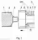
FIG. 1 is a longitudinal section of said assembly in initial position;
FIG. 2 is a longitudinal section of said assembly in the position of heating;
FIG. 3 is a longitudinal section of said assembly in the position of forming;
FIG. 4 is a longitudinal section of said assembly in final position.
EXEMPLARY EMBODIMENT OF THE INVENTION
The assembly for head welding in the figures consists of a mandrel 1, on which there is a head 3 and a tube body 2, put over in a typical manner, as well as of a cooling element, coaxial with the mandrel 1, and a nozzle D, coaxial with the mandrel 1. Said nozzle contains two parts—an internal one 7 and external one 8—which form a channel 9 for feeding a heating gas HG. The assembly consists of only one work station. The cooling element is also a forming element—OFE—and consists of a cooling metal ring 4 located in a forming metal ring 6. There is a heat-insulating ring 5 between the latter and the cooling metal ring 4. In the position of heating, said heat-insulating ring 5 is positioned around the end of the tube body 2.
In the assembly for head welding, the heat-insulating ring 5 is of a solid-state material or gas of low thermal conduction.
FUNCTIONING OF THE INVENTION
The assembly for head welding functions as described below. After placing the head 3 and the tube body 2 on the mandrel 1, the element OFE is moved, along with the nozzle D, towards the zone of welding. Simultaneously with that, the heating gas HG is fed as well. The element OFE and nozzle D stop at a position where an open heating chamber 10 is formed, providing different heating of the end of the tube body 2 by forming two zones for its cooling—an internal one 11, cooled to a temperature lower than the melting point of the foil (by the cooling metal ring 4), and an end one 12, almost non-cooled and having a temperature which is a bit above the melting point of the foil (due to the heat-insulating ring 5), while, in the same time, the head 3 is heated in the welding zone to a temperature being a bit higher than the melting point of the material of which said head is made. After that the weld is formed (by the element OFE), and the nozzle D is returned into its initial position, as a result of which feeding of the heating gas HG to the zone of welding is terminated. After the weld is cooled, the element OFE is also drawn out to its initial position, the component obtained is removed from the mandrel 1 and again the head 3 and the tube body 2 are placed on the mandrel 1. Then the process is repeated. In such a way, as the forming is performed immediately after heating, it is not necessary to overheat the tube body 2. The weld obtained is of high quality, and the reject percentage is minimal.
REFERENCE
1. Manual for Operating a Machine for Manufacturing Laminate Tubes “Kombis® 5501”, Mehatronika AD, Gabrovo, 2005.
Claims
1. An assembly for head welding, consisting of a mandrel 1, on which there is a head 3 and a tube body 2, put over in a typical manner, as well as of a cooling element, coaxial with the mandrel 1, and a nozzle D, coaxial with the mandrel 1, said nozzle containing two parts—an internal one 7 and external one 8—which form a channel 9 for feeding a heating gas HG, characterized in that it consists of only one work station, the cooling element being also a forming element and consisting of a cooling metal ring 4, located in a forming metal ring 6, and there being a heat-insulating ring 5 between the latter and the cooling metal ring 4, wherein in the position of heating said heat-insulating ring 5 is positioned around the end of the tube body 2.
2. The assembly for head welding according to claim 1, characterized in that the heat-insulating ring 5 is of a solid-state material or gas of low thermal conduction.
Images & Drawings included:


Sources:
- United States Patent and Trademark Office - verify current appl. status at the USPTO↗
Similar patent applications:
- » 20180126478
WELDING HEAD AND WELDING HEAD ASSEMBLY FOR AN ARC-WELDING SYSTEM - » 20180126479
Welding head and welding head assembly for an arc-welding system - » 20130026149
Welding head and welding head assembly for an arc-welding system - » 20240017499
A Welding Head Assembly - » 20180369966
Modular welding head assembly - » 20090050606
Changeable welding head assembly - » 10334347
Gas diffuser for head tube assembly of welding gun - » 20230330771
LENS ASSEMBLY AND LASER WELDING HEAD - » 20090011187
Method of Manufacturing Plastic Component Assembly and Plastic Component Assembly, and Plastic Component Welding Head and Plastic Component Welding Machine - » 20060065135
Vibrator assembly for strapping machine weld head
Recent applications in this class:
- » 20200039113 2020-02-06
Apparatus and method for heating pipes made of thermoplastic material - » 20170368717 2017-12-28
CPVC pipe fitting having improved resistance to environmental stress cracking - » 20170036374 2017-02-09
Apparatus and method for heating pipes made of thermoplastic material - » 20120273480 2012-11-01
Heating system and method of heating a body of a preform - » 20110204100 2011-08-25
Hot gas nozzle for heating a double-tube, a tube filling machine comprising a hot gas nozzle and a method for sealing a double tube - » 20110203579 2011-08-25
Oven for the thermal conditioning of preforms made of a thermoplastic material - » 20110045116 2011-02-24
Apparatus for severing and collecting IV tubing tips - » 20110027334 2011-02-03
Multilayer medical devices having an encapsulated edge and methods thereof - » 20100295217 2010-11-25
Method and tempering device for heating preforms prior to molding the same to form containers - » 20100215793 2010-08-26
DEVICE FOR IMPLEMENTING A SOCKET ON AN END OF CROSSCUT PLASTIC PIPES