Driving control device and method for power converting system
US20110050187A1
2011-03-03
12/547,563
2009-08-26
✅ Patent granted
US 8,080,986 B2
2011-12-20
-
-
Shawn Riley
2030-02-12
Abstract:
A driving control device and method for power converting system includes power converting circuit and driving control device. The driving control device has an analog/digital convertor, a measuring device, and a control module. The driving control method is the analog/digital convertor receives a inductor current and the parameters of the inductor current from the measuring device, measures the slope parameter of the inductor current according the parameters from Equation 1 and Equation 2, then calculates a duty cycle parameter from the slope parameter of the inductor current and use the duty cycle parameter to generate pulse control signal to perform driving control.
Inventors:
- Yen-Shin Lai 8 🇹🇼 Taipei, Taiwan
- Yen-Shin LAI 8 🇹🇼 Taipei City, Taiwan
- Ye-Then Chang 1 🇹🇼 Taipei City, Taiwan
- Ye-Then Chang 1 🇹🇼 Taipei, Taiwan
Assignee:
- NATIONAL TAIPEI UNIVERSITY TECHNOLOGY 11 🇹🇼 Taipei, Taiwan
Interested in similar patents?
Get notified when new applications in this technology area are published.
Classification:
H02M1/0009 » CPC further
Details of apparatus for conversion; Details of control, feedback or regulation circuits Devices or circuits for detecting current in a converter
Y02B70/10 » CPC further
Technologies for an efficient end-user side electric power management and consumption Technologies improving the efficiency by using switched-mode power supplies [SMPS], i.e. efficient power electronics conversion e.g. power factor correction or reduction of losses in power supplies or efficient standby modes
G05F1/10 IPC
Automatic systems in which deviations of an electric quantity from one or more predetermined values are detected at the output of the system and fed back to a device within the system to restore the detected quantity to its predetermined value or values, i.e. retroactive systems Regulating voltage or current
G05F1/00 IPC
Automatic systems in which deviations of an electric quantity from one or more predetermined values are detected at the output of the system and fed back to a device within the system to restore the detected quantity to its predetermined value or values, i.e. retroactive systems
Description
BACKGROUND OF THE INVENTION
1. Field of the Invention
This invention relates to a driving control device and method for power converting system specialized in automatically calculating the slope parameter for inductor current and providing this parameter to the power converting system for driving the control.
2. Description of the Prior Art
The conventional digital-controlled switching power converting circuit is better than the analog-controlled ones because the circuit aged slower, less power consumption, easier to modify the algorithms, and easier to design and accomplish. But the quick analog/digital convertor senses and feedbacks current and voltage to the digital controller, sampling frequency will affect the result. It needs to raise the sampling frequency to observe more data to solve this problem and minimize the error.
Raising the sampling frequency causes more converting time and as part of the feedback loop, it also causes extra phase lag. Besides the phase lag in analog control, the delay of converting process will result in extra waiting loop and slow down the instant reaction. High sampling frequency analog/digital convertor is also more expensive.
So as to avoid the delay of converting and save cost on components, it is necessary to lower sampling frequency. Under the condition of low sampling frequency, a practical way is to use inductance to calculate the slope parameter for inductor current of switching power converting circuit while controlling current, and use it to control the duty cycle of pulse signals.
As shown in FIG. 1 is an oscillogram of current used technology. With the known slope parameter for inductor current m1 and m2, the duty cycle of pulse signal can be determined by referring to the difference between the referring current Iref and sampling inductor current iL,1, and the slope parameter for inductor current (use sampling period T[n] to sample inductor current iL and calculate the width of the pulse control signal D[n]·T[n]). Since the actual inductance is hard to obtained and measured, high-accuracy current control cannot be achieved because there is no accurate slope parameter for inductor current.
So as to know, the current known practice has lot of drawbacks, is not a good design, and must be improved.
Noticing the disadvantages of the current method mentioned the inventor of this invention dedicates to improvement and invention. After years of hard working, this invention of automatically measuring the inductor current slope parameter for driving control device and method for power converting system is successfully invented.
SUMMARY OF THE INVENTION
The primary objective for this invention is to provide a driving control device and method for power converting system to solve the problem of actual inductance that is hard to obtained and measured.
The second objective for this invention is to provide a driving control device and method for power converting system whose power converting system can detect the slope parameter of inductor current, to help high-accuracy digital controlled low sampling frequency in power converting system.
The driving control device and method for power converting system of the present invention that achieve the purposes mentioned above convert direct current (DC) input voltage Vin to DC output voltage Vo. The power converting system contains a power converting circuit and a driving control device. The driving control device includes an analog/digital convertor, a measuring unit, and a control module. The analog/digital convertor converts the output voltage and inductor current into digital parameters. The measuring unit collects data of parameters of the inductor current, duty cycle of the switching unit, and sampling pulse signal. It uses Eq. 1, Eq. 2 (described below), and the data it collects to calculate the slope parameter of the inductor current. It also uses the duty cycle calculated from the slope parameter of inductor current to generate pulse control signal to operate the open or close of the switching device.
The technical theory used in this invention is automatically detecting the slope parameter of inductor current to help accomplishing high-accuracy digital control in power converting system with low sampling frequency.
BRIEF DESCRIPTION OF THE DRAWINGS
FIG. 1 shows the oscillogram of switching power converting circuit of conventional technology;
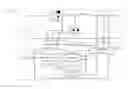
FIG. 2 shows the power converting system layout for this invention of driving control device and method for power converting system;
FIG. 3 shows the trailing edge modulation oscillogram of this invention of driving control device and method for power converting system;
FIG. 4 shows the leading edge modulation oscillogram of this invention of driving control device and method for power converting system;
FIG. 5 shows the triangle modulation 1 oscillogram of this invention of driving control device and method for power converting system;
FIG. 6 shows the triangle modulation 2 oscillogram of this invention of driving control device and method for power converting system;
FIG. 7 shows the single switching period dual sampling modulation 1 oscillogram of this invention of driving control device and method for power converting system; and
FIG. 8 shows the single switching period dual sampling modulation 2 oscillogram of this invention of driving control device and method for power converting system.
DETAILED DESCRIPTION OF THE PREFERRED EMBODIMENT
Please refer to FIG. 2 for the power converting system layout of driving control device and method for power converting system according to the present invention. The power converting system 1 converts DC input voltage Vin to DC output voltage Vo. The power converting system 1 contains a power converting circuit 11 and a driving control device 12. The power converting circuit 11 composes of a driving unit 111, two switching devices Q1 and Q2 driven by driving unit 111 to open or close, an inductor L and a capacitor C interfaced with switching unit Q1 and Q2, and a current detector 112 to detect the inductor current iL on the inductor L. This power converting circuit 11 is a DC to DC power converting circuit but can be made into an alternating current (AC) to DC or a DC to AC power converting circuit with different coupling method and driving control.
The driving control device 12 is interfaced with the power converting circuit 11. It includes an analog/digital convertor 121 that converts the analog output voltage Vo and inductor current iL into digital parameters of output voltage Vo[n] and inductor current iL[n]; a measuring unit 122 interfaced with analog/digital convertor 121 and control module 123, which collects data of parameters of the inductor current, duty cycle of the switching units, and sampling pulse signals, uses Eq. 1, Eq. 2 (described below), and the data it collects to calculate the slope parameter of the inductor current; and a control module 123 which has a controller 1231 to receive the reference voltage Vref and feedback the calculated reference current Iref as pre-defined in the control module and a modulator 1232 to initiate signals calculated from the reference current Iref of controller 1231 output and the slopes m1 and m2 of inductor current calculated by measuring unit 122 to control unit 111 to send out control signals.
The modulator 1232 also determines and sends out sampling pulse signal to the analog/digital convertor 121 for it to start sampling and convert the sampled output voltage Vo and inductor current iL. The measuring unit 122 collects sampling pulse signal and D[n] and T[n] parameters of the switches from the modulator 1232 and the inductor current iL[n] parameter from the analog/digital convertor 121. The initial inductor current iL,1, the final inductor current iL,2, and the sampling inductor current iL,x are determined by the relative position of the sampling pulse signal and switching signal. With all parameters collected and calculated, Eq. 1 will be used to calculate m2, the falling slope parameter of inductor current of inductor L, and Eq. 2 will be used to calculate m1, the rising slope parameter of inductor current of inductor L.
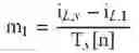
As using Eq. 1 to calculate m2, the falling slope parameter of inductor current, T[n] means the sampling period of the pulse control signal, Tx[n] means the sampling time for the inductor current to measured, iL,x means the inductor current at sampling time Tx[n], and iL,2 means the final inductor current for sampling period T[n]. Eq. 1 is defined as:
m 2 = i L , x - i L , 2 T [ n ] - T x [ n ] ( Equation 1 )
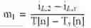
As using Eq. 2 to calculate m1, the rising slope parameter of inductor current, T[n] means the sampling period of the pulse control signal, Tx[n] means the sampling time for the inductor current to measured, iL,x means the inductor current at sampling time Tx[n], and iL,2 means the final inductor current for sampling period T[n]. Eq. 2 is defined as:
m 1 = i L , x + m 2 · ( T x [ n ] - D [ n ] · T [ n ] ) - i L , 1 D [ n ] · T [ n ] ( Equation 2 )
The modulator 1232 uses the slope parameters m1 and m2 of inductor current from Eq. 1 and Eq. 2 to calculate the duty cycle parameter D[n+1] for the (n+1)th sampling point. This duty cycle parameter D[n+1] is for the driving unit 111 to control the open or close of switching units Q1 and Q2 by pulse control signals.
Different modulator 1232 will have different modules so the control module can have six different modules for pulse control signals. The six types are trailing edge modulation, leading edge modulation, triangle modulation 1, triangle modulation 2, single switching period dual sampling modulation 1, and single switching period dual sampling modulation 2. Different equations are used to calculate the slope parameters m1 and m2 for inductor current as shown in Table 1 to Table 6.
Here is the process of driving control method for power converting system:
-
- 1. The analog/digital convertor measures the inductor current on the power converting circuit.
- 2. The measuring unit collects data of the parameters of the inductor current and calculates the slope parameters of the inductor current for the inductor using Eq. 1 and Eq. 2.
- 3. The control module uses the slope parameter to calculate a duty cycle parameter and generate a pulse control signal to perform driving control according to this duty cycle parameter.
FIG. 3 through FIG. 8 show the oscillogram of this invention of driving control device and method for power converting system with different modulations. According to the figures, sampling an extra inductor current iL,x along with inductor current iL at sampling period T[n] can be used to calculate the rising slope parameter m1 and the falling slope parameter m2 of inductor current, and calculate the width of the pulse control signal D[n]·T[n].
The inductor current parameters that the measuring unit collects include:
-
- 1. The initial inductor current iL,1 measures at the start of the pulse control signal sampling period T[n];
- 2. The final inductor current iL,2 measures at the end of the pulse control signal sampling period T[n];
- 3. A sampling inductor current iL,x measures at a given time Tx[n] during the pulse control signal sampling period T[n];
| TABLE 1 |
| Equations for trailing edge modulation |
| Sampling | Trailing Edge Modulation |
| Time | m1 | m2 |
| Tx[n] > D[n] · T[n] | m 1 = i L , x + m 2 · ( T x [ n ] - D [ n ] · T [ n ] ) - i L , 1 D [ n ] · T [ n ] | m 2 = i L , x - i L , 2 T [ n ] - T x [ n ] |
| Tx[n] < D[n] · T[n] | m 1 = i L , x - i L , 1 T x [ n ] | m 2 = i L , x + m 1 · ( D [ n ] · T [ n ] - T x [ n ] ) - i L , 2 ( 1 - D [ n ] ) · T [ n ] |
| TABLE 2 |
| Equations for leading edge modulation |
| Sampling | Leading Edge Modulation |
| Time | m1 | m2 |
| Tx[n] > (1−D[n]) · T[n] | m 1 = i L , 2 - i L , x T [ n ] - T x [ n ] | m 2 = i L , 1 + m 1 · ( T x [ n ] - ( 1 - D [ n ] ) · T [ n ] ) - i L , x ( 1 - D [ n ] ) · T [ n ] |
| Tx[n] < (1−D[n]) · T[n] | m 1 = i L , 2 + m 2 · ( ( 1 - D [ n ] ) · T [ n ] - T x [ n ] ) - i L , x D [ n ] · T [ n ] | m 2 = i L , 1 - i L , x T x [ n ] |
| TABLE 3 |
| Equations for triangle modulation 1 |
| Trailing Modulation 1 |
| Sampling Time | m1 | m2 |
| T x [ n ] < 1 2 ( 1 - D [ n ] ) · T [ n ] | m 1 = i L , 2 + m 2 · ( 1 - D [ n ] ) · T [ n ] - m 2 · T x [ n ] - i L , x D [ n ] · T [ n ] | m 2 = i L , 1 - i L , x T x [ n ] |
| T x [ n ] > 1 2 ( 1 + D [ n ] ) · T [ n ] | m 1 = i L , x - m 2 · D [ n ] · T [ n ] + m 2 · T x [ n ] - i L , 1 D [ n ] · T [ n ] | m 2 = i L , x - i L , 2 T [ n ] - T x [ n ] |
| TABLE 4 |
| Equations for triangle modulation 2 |
| Trailing Modulation 2 |
| Sampling Time | m1 | m2 |
| T x [ n ] < 1 2 D [ n ] · T [ n ] | m 1 = i L , x - i L , 1 T x [ n ] | m 2 = i L , x + m 1 · D [ n ] · T [ n ] - m 1 · T x [ n ] - i L , 2 ( 1 - D [ n ] ) · T [ n ] |
| T x [ n ] > T [ n ] - 1 2 D [ n ] · T [ n ] | m 1 = i L , 2 - i L , x T [ n ] - T x [ n ] | m 2 = i L , 1 + m 1 · ( D [ n ] - 1 ) · T [ n ] + m 1 · T x [ n ] - i L , x ( 1 - D [ n ] ) · T [ n ] |
| TABLE 5 |
| Equations for single switching period dual sampling modulation 1 |
| Sampling | Single switching period dual sampling Modulation 1 |
| Time | m1 | m2 |
| Tx[n] > (1−D[n]) · T[n] | m 1 = i L , 2 - i L , x T [ n ] - T x [ n ] | m 2 = i L , 1 + m 1 · ( T x [ n ] - ( 1 - D [ n ] ) · T [ n ] ) - i L , x ( 1 - D [ n ] ) · T [ n ] |
| Tx[n] < (1−D[n]) · T[n] | m 1 = i L , 2 + m 2 · ( ( 1 - D [ n ] ) · T [ n ] - T x [ n ] ) - i L , x D [ n ] · T [ n ] | m 2 = i L , 1 - i L , x T x [ n ] |
| TABLE 6 |
| Equations for single switching period dual sampling modulation 2 |
| Single switching period dual sampling Modulation 2 |
| Sampling Time | m1 | m2 |
| Tx[n] > D[n] · T[n] | m 1 = i L , x + m 2 · ( T x [ n ] - D [ n ] · T [ n ] ) - i L , 1 D [ n ] · T [ n ] | m 2 = i L , x - i L , 2 T [ n ] - T x [ n ] |
| Tx[n] < D[n] · T[n] | m 1 = i L , x - i L , 1 T x [ n ] | m 2 = i L , x + m 1 · ( D [ n ] · T [ n ] - T x [ n ] ) - i L , 2 ( 1 - D [ n ] ) · T [ n ] |
This invention of automatically calculating the slope parameter for inductor current for driving control device and method for power converting system has the following benefits over the current technologies:
-
- 1. This invention of driving control device and method for power converting system can detect and calculate the slope parameters m1 and m2 of inductor current on its own and help accomplishing high-accuracy digital control in power converting system with low sampling frequency.
- 2. This invention of driving control device and method for power converting system can be used in different modulations for high-accuracy digital control.
- 3. This invention of automatically calculating the slope parameter for inductor current for driving control device and method for power converting system whose power converting circuit can be a DC to DC, AC to DC, or DC to AC power converting circuit.
The aforementioned descriptions are solely for explaining the embodiments of the present invention and are not intended to limit the scope of the present invention. Any equivalent practice of modification within the spirit of the present invention should be treated as being within the scope of patent of the present invention.
As aforementioned, the present invention is novel in technology and advantaged in many effects that the prior arts lack. The present invention conforms to the novelty and non-obviousness of patentability. Please the examiner carefully considering the application of the present invention and allowing the application.
Claims
What is claimed is:1. A driving control device for power converting system interfaced with the power converting circuit, comprising:
an analog/digital convertor which converts analog output voltage and inductor current of an inductor into digital output voltage and inductor current parameters;
a measuring unit, interfaced with the analog/digital convertor and the control module, to collect data of inductor current parameters, duty cycle of switching devices, sampling pulse signal and calculate slope parameters of the inductor current of the inductor; and
a control module, interfaced with a driving unit and the analog/digital convertor, containing a controller and a modulator, to calculate the duty cycle parameter from the slope parameters of the inductor current and generate a pulse control signal to operate open or close of the switching devices through the driving unit.
2. The driving control device for power converting system as claimed in claim 1, wherein the power converting circuit includes the driving unit, multiple switching units operated by the driving unit, the inductor coupled with a switching unit, a capacitor coupled with a switching unit, and a measuring device that can measure inductor current.
3. The driving control device for power converting system as claimed in claim 1, wherein the power converting circuit can be a DC to DC, AC to DC, or DC to AC power converting circuit.
4. The driving control device and method for power converting system as claimed in claim 1, wherein the control module can use trailing edge modulation, leading edge modulation, triangle modulation, or single switching period dual sampling modulation to generate pulse control signal.
5. A driving control method for power converting system whose steps comprise:
1) detecting inductor current of a power converting circuit by an analog/digital convertor;
2) collecting inductor current parameters and uses Equations with the parameters by a measuring unit to calculate slope parameters for the inductor current of the inductor;
3) using the slope parameters of the inductor current to calculate a duty cycle parameter by a control module and use it to generate a pulse control signal to perform driving control.
6. The driving control method for power converting system as claimed in claim 5, wherein the measuring unit collects parameters of the inductor current including:
1) initial inductor current iL,1 measuring at start of the pulse control signal sampling period T[n];
2) final inductor current iL,2 measuring at end of the pulse control signal sampling period T[n];
3) sampling inductor current iL,x measuring at a given time Tx[n] during the pulse control signal sampling period T[n].
7. The driving control method for power converting system as claimed in claim 5, wherein the Equations include Equation 1 and Equation 2 defined as:
m 2 = i L , x - i L , 2 T [ n ] - T x [ n ] ( Equation 1 ) m 1 = i L , x + m 2 · ( T x [ n ] - D [ n ] · T [ n ] ) - i L , 1 D [ n ] · T [ n ] ( Equation 2 )
wherein T[n] means the sampling period of the pulse control signal, Tx[n] means the sampling time for the inductor current to measured, iL,x means the inductor current at sampling time Tx[n], and iL,2 means the final inductor current for sampling period T[n].
8. The driving control method for power converting system as claimed in claim 7, wherein the Equation 1 and Equation 2 for calculating slope parameters for inductor current will be different according to modulation types.
9. The driving control method for power converting system as claimed in claim 8, wherein the modulation type can be trailing edge modulation, leading edge modulation, triangle modulation, or single switching period dual sampling modulation.
Images & Drawings included:


Sources:
- United States Patent and Trademark Office - verify current appl. status at the USPTO↗
Similar patent applications:
- » 20240348189
CONTROL DEVICE AND METHOD FOR CONTROLLING A POWER CONVERTER, AND ELECTRICAL DRIVE SYSTEM - » 20170359014
Control device of power converter, power conversion system, compressor driving system, flywheel power generation system, and control method for power converter - » 20200204086
Method for controlling a pulse-width-modulated power converter, control device for a pulse-width-modulated power converter, power converter assembly, and electrical drive system - » 20140232307
Vector control device for an electric motor that controls an electric power converter that converts DC power to AC power, electric motor, vehicle drive system, and vector control method for electric motor
Recent applications in this class:
- » 20250226751 2025-07-10
ELECTRIC POWER SUPPLY CONTROL DEVICE AND SWITCHING ELECTRIC POWER SUPPLY - » 20250219544 2025-07-03
MULTI-PHASE CIRCUIT CONTROL METHOD AND POWER CONVERSION DEVICE - » 20250211120 2025-06-26
OUTPUT CONDUCTION DETECTION IN A BUCK CONVERTER - » 20250183803 2025-06-05
METHOD AND APPARATUS FOR OVER-CURRENT PROTECTION AND CRCM CONTROL IN POWER CONVERTERS - » 20250088113 2025-03-13
POWER SUPPLY CONTROL DEVICE AND SWITCHING POWER SUPPLY APPARATUS - » 20250055375 2025-02-13
SEMICONDUCTOR DEVICE AND SWITCHING POWER SUPPLY - » 20250047205 2025-02-06
Switching Power Supply - » 20250038669 2025-01-30
Semiconductor Device, Semiconductor System and Switching Power Device - » 20250030346 2025-01-23
POWER SUPPLY CONTROLLER AND SWITCHING POWER SUPPLY - » 20250030345 2025-01-23
POWER CONVERSION DEVICE AND CONTROL METHOD THEREOF
Recent applications for this Assignee:
- » 20110130268 2011-06-02
Dielectric ceramic composition - » 20100273632 2010-10-28
Glass-ceramic composite encapsulation material - » 20100065257 2010-03-18
REFRIGERANT COOLING SYSTEM FOR AN ELECTRONIC APPARATUS AND THE METHOD THEREOF - » 20090321968 2009-12-31
Structure of cooling tower - » 20080285033 2008-11-20
Method and device for characterizing analyte using electro-optically modulated surface plasmon resonance based on phase detection - » 20070056315 2007-03-15
Electrohydrodynamic condenser device - » 20070051129 2007-03-08
Electrohydrodynamic evaporator device - » 20060011397 2006-01-19
Remote control vehicle with UV sterilizer - » 12360333 2010-06-01
Method for production of diamond-like carbon film having semiconducting property - » 10327971 2005-12-20
Miniature three-dimensional contour scanner