MEMORY CARD CONNECTOR
US20110053424A1
2011-03-03
12/546,869
2009-08-25
Abstract:
The present invention relates to a memory card connector, comprises an insulation main body on which an insertion slot and a plurality of terminal slots are installed, and two ends thereof are respectively provided with a tower having a guiding slot, a positioning concave slot and a limiting block, wherein the insertion slot and the guiding slot are served to be inserted with a memory card; a plurality of terminals respectively received in the plural terminal slots; and two lugs, each of the lugs has a pin shaft and a limiting part, the pin shaft is disposed in the positioning concave slot, the lug is limited in the limiting block when the lug is pivotally moved through the pin shaft so as to respectively buckle on the tower.
Interested in similar patents?
Get notified when new applications in this technology area are published.
Classification:
H01R13/62988 » CPC main
Details of coupling devices of the kinds covered by groups or -; Means for facilitating engagement or disengagement of coupling parts or for holding them in engagement; Additional means for facilitating engagement or disengagement of coupling parts, e.g. aligning or guiding means, levers, gas pressure electrical locking indicators, manufacturing tolerances; Linear camming means or pivoting lever for connectors for flexible or rigid printed circuit boards, flat or ribbon cables Lever acting directly on flexible or rigid printed circuit boards, flat or ribbon cables, e.g. recess provided to this purposeon the surface or edge of the flexible or rigid printed circuit boards, flat or ribbon cables
H01R12/721 » CPC further
Structural associations of a plurality of mutually-insulated electrical connecting elements, specially adapted for printed circuits, e.g. printed circuit boards [PCBs], flat or ribbon cables, or like generally planar structures, e.g. terminal strips, terminal blocks; Coupling devices specially adapted for printed circuits, flat or ribbon cables, or like generally planar structures; Terminals specially adapted for contact with, or insertion into, printed circuits, flat or ribbon cables, or like generally planar structures; Coupling devices for rigid printing circuits or like structures coupling with the edge of the rigid printed circuits or like structures cooperating directly with the edge of the rigid printed circuits
H01R24/00 IPC
Two-part coupling devices, or either of their cooperating parts, characterised by their overall structure
Description
BACKGROUND OF THE INVENTION
1. Field of the Invention
The present invention relates to a connector, more particularly to a memory card connector that can be used to fasten a memory card therein.
2. Description of Related Art
A memory card connector is widely used in a computer motherboard so a memory module is able to be installed therein, thus a central process unit (CPU) can access the memory module through the memory card connector. The memory card connector is such as an EDO DRAM, SDRAM, DDR DRAM and the latest DDRII RAM.
The stability of the computer mainframe relies on whether the memory module can be firmly fastened on the memory card connector. When the memory module is not able to be firmly fastened on the memory card connector, an error may occur when the computer mainframe is accessing data and a computer crash down is therefore caused.
To overcome the disadvantages mentioned above, a novel memory card connector is provided by the present invention to improve such shortages.
SUMMARY OF THE INVENTION
One object of the present invention is to provide a memory card connector, which can be used to firmly fasten a memory module within the memory card connector.
Another object of the present invention is to provide a memory card connector, of which structure is simple and production cost is lower.
For achieving the objects mentioned above, a memory card connector is provided by the present invention, comprises an insulation main body on which an insertion slot and a plurality of terminal slots are installed, and two ends thereof are respectively provided with a tower having a guiding slot, a positioning concave slot and a limiting block, wherein the insertion slot and the guiding slot are served to be inserted with a memory card; a plurality of terminals respectively received in the plural terminal slots; and two lugs, each of the lugs has a pin shaft and a limiting part, the pin shaft is disposed in the positioning concave slot, the lug is limited in the limiting block when the lug is pivotally moved through the pin shaft so as to respectively buckle on the tower.
BRIEF DESCRIPTION OF THE DRAWINGS
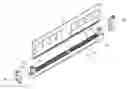
FIG. 1 is a schematic, exploded view of the memory card connector of one preferred embodiment of the present invention;
FIG. 2 is a schematic, partially-enlarged cross sectional view of the tower of one preferred embodiment of the present invention;
FIG. 3 is a schematic view of the lug of one preferred embodiment of the present invention;
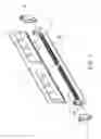
FIG. 4 is a schematic view illustrating the assembly of the lug and the memory card connector of one preferred embodiment of the present invention.
DETAILED DESCRIPTION OF THE PREFERRED EMBODIMENT
Referring from FIG. 1 to FIG. 4, wherein FIG. 1 is a schematic, exploded view of the memory card connector of one preferred embodiment of the present invention; FIG. 2 is a schematic, partially-enlarged cross sectional view of the tower of one preferred embodiment of the present invention; FIG. 3 is a schematic view of the lug of one preferred embodiment of the present invention; FIG. 4 is a schematic view illustrating the assembly of the lug and the memory card connector of one preferred embodiment of the present invention.
As shown in figures, the memory card connector 1 provided by the present invention, which can be served to connect a memory module 2, comprises an insulation main body 10, a plurality of terminals 20, and two lugs 30.
The insulation main body 10 is made of an insulation member, e.g. but not limited to, plastic, an insertion slot 11 and a plurality of terminal slots 12 are installed thereon and two ends thereof are respectively installed with a tower 13, the tower 13 has a guiding slot 131, a positioning concave slot 132 and a limiting block 133. The insertion slot 11 and the guiding slot 131 are served to be inserted with the memory module 2; the positioning concave slot 132 and the limiting block 133 are cooperated with the lugs 30.
The plural terminals 20 are respectively received in the plural terminal slots 12 so as to form an electrical connection, the terminals 20 are conventional terminals therefore would not be further illustrated.
As shown in FIG. 3, each of the two lugs 30 has a pin shaft 31 and a limiting part 32, wherein the pin shaft 31 is disposed in the positioning concave slot 132; the limiting part 32, e.g. but not limited to, protrudes from the bottom of the lug 30. The lug 30 is limited in the limiting block 133 through the limiting part 32 when the lug 30 is pivotally moved through the pin shaft 31, so the two lugs 30 are respectively buckled on the corresponding tower 13. Furthermore, the top end of the lug 30 is installed with at least one step-like transversal strip 33 to increase friction, so the tower 13 is easier to be pulled by a user.
The pin shaft 31 is disposed on top of the limiting part 32 and is in a round column shape, and protrudes from two ends of the lug 30, the pin shaft 31 is able to be received in the positioning concave slot 132 for operating a pivotal motion.
Two lateral ends of the lug 30 are further installed with a buckling block 34. The buckling block 34 is disposed at the same side where the limiting part 32 is installed and is disposed on top of the pin shaft 31, and protrudes from the two ends of the lug 30 so as to buckle on the tower 13. Two ends of the buckling block 34 respectively have a reversed angle part (not shown) and the two reversed angle parts have different angles.
As shown in FIG. 4, in assembly, the pin shaft 31 is received in the positioning concave slot 132 so as to achieve the assembly. When the lug 30 is outwardly and pivotally moved, the limiting part 32 thereof is disposed against and positioned in the limiting block 133; when the lug 30 is inwardly and pivotally moved, the limiting part 32 thereof is released from the limiting block 133 and is disposed against and positioned on one end of the tower 13, then is buckled on the tower 13 through the buckling block 34, so the memory module 2 is fastened therein.
As mentioned above, with the memory card connector provided by the present invention, the memory module can be firmly fastened in the memory card connector, and the structure of the memory card connector is simple and product cost thereof is lower.
It is to be understood, however, that even though numerous characteristics and advantages of the present embodiments have been set forth in the foregoing description, together with details of the structures and functions of the embodiments, the disclosure is illustrative only, and changes may be made in detail, especially in matters of shape, size, and arrangement of parts within the principles of the invention to the full extent indicated by the broad general meaning of the terms in which the appended claims are expressed.
Claims
1-6. (canceled)
7. A memory card connector comprising:
an insulation main body having an insertion slot, a plurality of terminal slots, and two towers, one of the two towers is located on each of two opposing ends of the insulation main body, each tower of the two towers has a guiding slot, a concave positioning slot and a limiting block, the insertion slot and the guiding slot are positioned for a memory module to be inserted therein;
a plurality of terminals respectively located in the plural terminal slots; and
two lugs, each lug of the two lugs has a pin shaft extending through the lug and protruding outwardly from two opposing sides thereof and a limiting part extending outwardly from a bottom of a front thereof, two opposing ends and a center of the pin shaft are located in the concave positioning slot, the lug is limited by the limiting block when the lug is pivoted around the pin shaft to respectively buckle on the tower.
8. The memory card connector according to claim 7, wherein a top of the each lug has at least one step-like transversal strip.
9. The memory card connector according to claim 7, wherein the limiting part protrudes from a bottom of the each lug.
10. The memory card connector according to claim 7, wherein the pin shaft is located above the limiting part and has a round column shape.
11. The memory card connector according to claim 10, wherein the each lug has a buckling block located on each of the two opposing sides thereof and located adjacent to the front thereof, the each buckling block is positioned above the pin shaft, each buckling block selectively engages a corresponding one of the two towers.
12. The memory card connector according to claim 11, wherein the each buckling block has two reversed angle parts, one of the two reversed angle parts is located on each of two opposing ends of a corresponding buckling part, and the two reversed angle parts have different angles.
Images & Drawings included:


Sources:
- United States Patent and Trademark Office - verify current appl. status at the USPTO↗
Similar patent applications:
- » 20160270219
Support entering into the fabrication of an electronic device, corresponding memory card connector, memory card read terminal and manufacturing method - » 20050003711
Memory card connector for accommodating different memory cards - » 20060046567
Memory card connector assembly for receiving multiple memory cards - » 20070004248
Memory card connector system for stabilizing the position of a contacted memory card - » 20050014405
Memory card connector - » 20050009389
Eject mechanism for memory card connector - » 20050003693
Memory card connector with switch terminals having improved contacts - » 20050059299
Memory card connector - » 20050009406
Switch terminal for memory card connectors - » 20050037659
Memory card connector
Recent applications in this class:
- » 20240222908 2024-07-04
MOTION COMPONENT STRUCTURE - » 20210119380 2021-04-22
Electrical interface fasteners - » 20200388962 2020-12-10
Retention latch with spring mechanism - » 20190363488 2019-11-28
Card edge connector equipped with ejector interacting with neighboring contacts - » 20180351296 2018-12-06
Plug Connection for use in a Magnetic Resonance Device - » 20150072549 2015-03-12
Card connector - » 20150017828 2015-01-15
Linkage apparatus for plugging PCB board - » 20140377972 2014-12-25
Card edge connector with an improved housing - » 20140213085 2014-07-31
Card edge connector with detecting structure - » 20120164859 2012-06-28
Card edge connector