Method for the optimal alignment of veneer sheets at a lay-up station
US20110057384A1
2011-03-10
12/877,291
2010-09-08
✅ Patent granted
US 9,790,045 B2
2017-10-17
-
-
Howard Sanders
Womble Carlyle Sandridge & Rice LLP
2033-05-21
Abstract:
The invention relates to a method for the optimal positioning of veneer sheets at a lay-up station, wherein the veneer sheets are attached for a veneer assembly composed of veneer sheets glued on top of each other. The method comprises determining an optimal position for each veneer sheet and a location for virtual alignment edges and laying up the veneer sheets as positioned in accordance with the virtual alignment edges, for a veneer assembly.
Assignee:
- RAUTE OYJ 38 🇫🇮 Nastola, Finland
Applicant:
Interested in similar patents?
Get notified when new applications in this technology area are published.
Classification:
B27D1/04 » CPC further
Joining wood veneer with any material; Forming articles thereby ; Preparatory processing of surfaces to be joined, e.g. scoring to produce plywood or articles made therefrom; Plywood sheets
B65H2220/01 » CPC further
Function indicators indicating an entity as a function of which control, adjustment or change is performed, i.e. input
B65H2220/02 » CPC further
Function indicators indicating an entity which is controlled, adjusted or changed by a control process, i.e. output
B65H2220/03 » CPC further
Function indicators indicating an entity which is measured, estimated, evaluated, calculated or determined but which does not constitute an entity which is adjusted or changed by the control process
B65H9/20 IPC
Registering, e.g. orientating, articles; Devices therefor Assisting by photoelectric, sonic, or pneumatic indicators
B65H9/00 IPC
Registering, e.g. orientating, articles; Devices therefor
B65H9/103 » CPC main
Registering, e.g. orientating, articles; Devices therefor; Pusher and like movable registers; Pusher or gripper devices which move articles into registered position acting by friction or suction on the article for pushing or pulling it into registered position, e.g. against a stop
B65H2301/4213 » CPC further
Handling processes for sheets or webs; Type of handling process; Piling, depiling, handling piles; Forming a pile of a limited number of articles, e.g. buffering, forming bundles
B65H2301/4219 » CPC further
Handling processes for sheets or webs; Type of handling process; Piling, depiling, handling piles; Forming a pile forming a pile in which articles are offset from each other, e.g. forming stepped pile
B65H2511/10 » CPC further
Dimensions; Position; Numbers; Identification; Occurrences Size; Dimensions
B65H2511/216 » CPC further
Dimensions; Position; Numbers; Identification; Occurrences; Location in space; Angle Orientation, e.g. with respect to direction of movement
B65H2551/29 » CPC further
Means for control to be used by operator; User interfaces; Display means; Information output means Means displaying permanently a particular information, e.g. mark, ruler
B65H2553/42 » CPC further
Sensing or detecting means using optical, e.g. photographic, elements Cameras
B65H7/02 IPC
Controlling article feeding, separating, pile-advancing, or associated apparatus, to take account of incorrect feeding, absence of articles, or presence of faulty articles by feelers or detectors
B65H9/10 IPC
Registering, e.g. orientating, articles; Devices therefor Pusher and like movable registers; Pusher or gripper devices which move articles into registered position
B65H7/06 » CPC further
Controlling article feeding, separating, pile-advancing, or associated apparatus, to take account of incorrect feeding, absence of articles, or presence of faulty articles by feelers or detectors responsive to presence of faulty articles or incorrect separation or feed
B65H29/34 » CPC further
Delivering or advancing articles from machines; Advancing articles to or into piles by dropping the articles from supports slid from under the articles
B65H2701/1938 » CPC further
Handled material; Storage means; Handled articles or webs; Specific article or web Veneer sheet
Description
CROSS-REFERENCE TO RELATED APPLICATION
This application claims priority from and the benefit under 35 U.S.C. §119 of Finnish Patent Application No. 20095931, filed Sep. 9, 2009 in the Finnish Patent Office, which is hereby incorporated herein by reference in its entirety.
FIELD OF THE DISCLOSURE
The present invention relates to a method for the optimal alignment of veneer sheets at a lay-up station, wherein the veneer sheets are laid up for a veneer assembly composed of veneer sheets glued on top of each other.
BACKGROUND OF THE DISCLOSURE
In the manufacture of plywood panels or laminated veneer lumber (LVL), the veneers are laid up at a lay-up station for a veneer assembly with a thickness of several veneer layers. Top surfaces of the veneers have adhesive applied thereto and the veneers are laid on top of each other and then, in the next working step, brought to a permanent attachment with each other by the application of pressure and heat. This calls for a precise alignment of veneers relative to each other. Traditionally, the alignment has been performed manually against two stationary fences. At present, the lay-up operation is often machine-operated, but two stationary fences are still involved one way or another. The manufacture of LVL has involved the use of a mechanical lay-up operation. However, the LVL is structurally different with its veneers supposedly parallel to each other. The application publication US 2003/0173734 describes one LVL manufacturing apparatus and method, enabling a precise alignment of veneer sheets relative to each other by adapting what in the advancing direction of a veneer sheet constitutes its leading edge to function as an alignment edge and by positioning the veneer sheets at a lay-up station on top of a two-segment tablet arrangement, said tablet segments being adapted to move towards and away from each other. In this solution, the identification of a leading edge position is used as a controlling parameter for the process. Still, even in this solution, the leading edge is identified by mechanical brackets in just two positions.
SUMMARY OF THE DISCLOSURE
An objective of the present invention is to provide an improved solution, enabling a better consideration of defects in veneer sheets for optimizing the position of alignment edges. In order to achieve this objective, a method according to the invention is characterized in that the method comprises determining an optimal position for each veneer sheet and virtual locations for alignment edges, and laying up the veneer sheets, as positioned in accordance with the virtual alignment edges, for a veneer assembly.
In the context of this application, the virtual alignment edge refers to an optimal location of alignment edges, said alignment edges being in a substantially perpendicular relationship with each other, considering e.g. defects in the immediate vicinity of a real veneer edge in such a way that the defects shall end up in a portion to be cut off in a subsequent operation and, on the other hand, in such a way that a maximal surface area of the veneers can be utilized. Defects can be e.g. in the form of a sizable knot hole, a split or cracked veneer portion, an edge waviness, etc. The alignment can also be conducted in a totally visual manner by using e.g. laser lines as an alignment edge. Once a veneer assembly has been composed of the veneers, the veneer assembly shall be conveyed to a trimming operation for the virtual alignment edge to become a real alignment edge in the trimming operation, and especially in such a way that the defects of intermediate veneers shall not be visible until after an edge sawing operation.
BRIEF DESCRIPTION OF THE DRAWINGS
The invention will now be described more closely with reference to the accompanying drawings, in which:
FIG. 1 shows a traditional lay-up practice in a schematic view of principle,
FIG. 2 shows in a schematic view of principle one lay-up practice implemented according to the present invention,
FIG. 3 shows in a schematic view of principle a second lay-up practice implemented according to the present invention, and
FIG. 4 shows a veneer assembly trimming operation in a schematic view of principle.
DETAILED DESCRIPTION OF THE DRAWINGS
FIG. 1 depicts a traditional way of laying up veneer sheets, wherein veneer sheets 1, l′, 1″ are aligned against stationary fences 13, 14 set in a perpendicular relationship with each other. This method has been in active service for a long time, but it has a problem in the sense that the veneers may end up in an undesirable position. In FIG. 1, the uppermost veneer 1 is shown in such incorrect position, the result of which is that the veneers must be sawn to a slight oversize in order to ensure a correct size for the veneer assembly after the edge sawing operation.
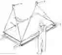
FIG. 2 shows a method of the invention, in which the laying up of veneers is conducted manually by using laser lines to indicate the location of a virtual alignment edge. Laser pointers 3, 4 produce two laser lines perpendicular to each other, which enable the operator to align a veneer 1 arriving at the lay-up operation on top of a most recently laid-up veneer 2 in an optimal manner. The operator aligns the veneer 1 in consideration of possible defects present in the leading edge closest to himself for making maximum use of the veneer in terms of its surface area.
FIG. 3 illustrates a second lay-up practice of the invention, in which the veneers are positioned automatically. In this embodiment, the production line is provided with a camera 8 placed upstream of a lay-up station, said camera checking the dimensions of a veneer and calculating whether it is sufficient for a panel, and concluding which is the optimal position to set it. A veneer with insufficient dimensions is rejected from the assembly. When a veneer conveyed by belts arrives at the lay-up station, it will be captured by grippers 5, 5′ whose position at the end of support brackets 6, 6′ is precisely known and, at the same time, a second camera 7 is used for checking a true position of the veneer, followed by calculating an alignment position for the veneer. This enables determining precisely the position of a veneer in the coordinate system of a robot. After this, the veneer is conveyed to a desired lay-up point and lowered down. In the presented embodiment, the veneer is lowered on top of a panel 9 by means of the support brackets 6, 6′. Then, the panel 9 is moved away from under the veneer, whereby one end of the veneer descends and attaches to the stack with adhesive. This is followed by withdrawing the support brackets 6, 6′.
One alternative to the foregoing mode of operation is such that, as a veneer conveyed by belts arrives at a lay-up station, said veneer can be dropped onto a panel tablet traveling forward at a speed equal to that of the veneer, or onto some other veneer-receiving carrier. After the tablet has advanced across a halfway point, the grippers are able to take hold of the veneer, followed by performing necessary straightening operations, and then the tablet or another carrier can be pulled away from under for taking up the next veneer.
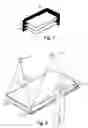
Once completed, the veneer assembly is conveyed for a trimming operation e.g. to an edge sawing apparatus, which is used for sawing the veneer assembly to provide it with an edge consistent with a virtual alignment edge and a desired amount of tolerance. One alignment edge 10′ is preferably the edge which is leading in the advancing direction of a veneer upon its arrival at the lay-up station, and a second alignment edge 10 is the edge perpendicular thereto. From the lay-up station, the veneer assemblies depart preferably in a direction perpendicular to the original advancing direction, such that the alignment edge 10′ lies in a parallel relationship with the veneer assembly's advancing direction and can be sawn without stopping the veneer assembly. Preferably, the edge opposite to the alignment edge is also sawn at the same time by driving the veneer assembly across saw blades 12′, 12 set at a desired crosswise distance from each other. The short sides perpendicular to the alignment edge are trimmed in such a way that the conveyor can be stopped e.g. on the basis of a pulse sensor reading, or such sides can be trimmed while the action is going on by using a so-called flying saw or a saw which advances in the same direction as the veneer assembly at the same speed while having its blade advancing across the veneer assembly. During the trimming operation, the veneer assembly is held e.g. by a belt 11.
A virtual edge can also be marked with some prior known method, which marking remains fixed in various operations of the process. Such a method may comprise e.g. marking a virtual edge by means of a perforation or another mechanical indication. The perforation can be made e.g. by drilling or punching a required number of marking holes or recesses in a veneer sheet. The marking can also be made e.g. with an ink jet printer or some other instrument producing a permanent imprint.
Claims
1. A method for the optimal positioning of veneer sheets at a lay-up station, wherein the veneer sheets are attached for a veneer assembly composed of veneer sheets glued on top of each other, wherein the method comprises determining an optimal position for each veneer sheet and a location for virtual alignment edges, and laying up the veneer sheets, as positioned in accordance with the virtual alignment edges, for a veneer assembly.
2. A method as set forth in claim 1, wherein the method comprises determining the virtual alignment edges for the veneer sheet and a true location of the veneer sheet at a lay-up station on the basis of a camera image, and, on the basis of obtained image data, the veneer sheets positioned in accordance with the virtual alignment edges are positioned on a veneer assembly by means of positioning elements.
3. A method as set forth in claim 1, wherein the method comprises determining the virtual alignment edges for the veneer sheet (1, 2) on the basis of a camera image and determining a true location of the veneer sheet at a lay-up station on the basis of the same camera image, and, on the basis of obtained true location data, the veneer sheets positioned in accordance with the virtual alignment edges are positioned on a veneer assembly by means of positioning elements.
4. A method as set forth in claim 1, wherein the lay-up operation is followed by trimming the veneer assembly consistently with at least one virtual alignment edge, such that said at least one virtual alignment edge becomes a real alignment edge.
5. A method as set forth in claim 4, wherein all edges of the veneer assembly are trimmed after the lay-up operation.
6. A method as set forth in claim 1, wherein the virtual alignment edges are marked mechanically by making alignment holes or indications in the veneer sheet.
Images & Drawings included:


Sources:
- United States Patent and Trademark Office - verify current appl. status at the USPTO↗
Recent applications in this class:
- » 20250171260 2025-05-29
METHOD FOR ACTIVATING AT LEAST ONE ALIGNMENT SEGMENT OF A PROCESSING MACHINE - » 20240101381 2024-03-28
SHEET TRANSPORTING DEVICE AND IMAGE FORMING APPARATUS - » 20230312292 2023-10-05
Sheet transport device and image forming apparatus - » 20160257513 2016-09-08
SHEET-TYPE MEDIUM DEVIATION CORRECTION DEVICE AND AUTOMATIC TELLER MACHINE - » 20130082441 2013-04-04
Translatable roller media aligning mechanism - » 20120031733 2012-02-09
Apparatus for aligning a sheet product - » 20100126827 2010-05-27
Apparatus for aligning vouchers - » 20090295076 2009-12-03
Sheet conveying device and image forming apparatus - » 20080295722 2008-12-04
METHOD AND APPARATUS FOR PRE-STAGING PRINTING PLATES - » 20080054555 2008-03-06
Image forming apparatus
Recent applications for this Assignee:
- » 20220219351 2022-07-14
Veneer lathe and method of producing veneer - » 20220032491 2022-02-03
System and method for repairing plywood - » 20210316336 2021-10-14
System and a method for sorting veneer sheets - » 20210247136 2021-08-12
Conditioning system for wood processing and a method thereto - » 20180231310 2018-08-16
Jet box and a dryer using the same - » 20150020717 2015-01-22
METHOD FOR OPTIMIZING THE OPERATION OF A GAS GENERATOR AND A GAS GENERATOR - » 20130164111 2013-06-27
Stacking device - » 20130074990 2013-03-28
ROLL ARRANGEMENT FOR A VENEER LATHE - » 20120328405 2012-12-27
Apparatus for receiving and positioning veneers fed in a position with camera - » 20120279666 2012-11-08
Press apparatus for wood products