Lens module of scanner
US20110058264A1
2011-03-10
12/877,601
2010-09-08
✅ Patent granted
US 7,982,962 B2
2011-07-19
-
-
Scott J Sugarman
2030-09-08
Abstract:
A lens module of a scanner is provided, including a first lens with a positive diopter, a second lens with a negative diopter, a third lens with a positive diopter, and a fourth lens with a negative diopter. The first, second, third, and fourth lenses are sequentially arranged from an object end to an image end of the lens module, and at least one of the first and fourth lenses is an aspheric lens. The fourth lens has a focal length f4 and an objective side surface with a radius of curvature R7, wherein 0.1<R7/f4<1.
Assignee:
- ASIA OPTICAL CO., INC. 473 🇹🇼 Taichung, Taiwan
Interested in similar patents?
Get notified when new applications in this technology area are published.
Classification:
G02B9/34 IPC
Optical objectives characterised both by the number of the components and their arrangements according to their sign, i.e. + or - having four components only
G02B13/24 » CPC main
Optical objectives specially designed for the purposes specified below for reproducing or copying at short object distances
G02B9/14 » CPC further
Optical objectives characterised both by the number of the components and their arrangements according to their sign, i.e. + or - having three components only arranged + - +
H04N1/1017 » CPC further
Scanning, transmission or reproduction of documents or the like, e.g. facsimile transmission; Details thereof; Scanning arrangements, i.e. arrangements for the displacement of active reading or reproducing elements relative to the original or reproducing medium, or using flat picture-bearing surfaces with sub-scanning by translatory movement of at least a part of the main-scanning components the main-scanning components remaining positionally invariant with respect to one another in the sub-scanning direction
H04N2201/02431 » CPC further
Indexing scheme relating to scanning, transmission or reproduction of documents or the like, and to details thereof deleted; Arrangements for positioning elements within a head; Element positioned Lens or optical system
H04N2201/02458 » CPC further
Indexing scheme relating to scanning, transmission or reproduction of documents or the like, and to details thereof deleted; Arrangements for mounting or supporting elements within a scanning head; Element mounted or supported Lens or optical system
G02B3/00 IPC
Simple or compound lenses
G02B26/10 IPC
Optical devices or arrangements for the control of light using movable or deformable optical elements for controlling the direction of light Scanning systems
G02B13/18 IPC
Optical objectives specially designed for the purposes specified below with lenses having one or more non-spherical faces, e.g. for reducing geometrical aberration
Description
CROSS REFERENCE TO RELATED APPLICATIONS
This Application claims priority of Taiwan Patent Application No. 098130375, filed on Sep. 9, 2009, the entirety of which is incorporated by reference herein.
BACKGROUND OF THE INVENTION
1. Field of the Invention
This application relates in general to an optical device and in particular to a lens module of a scanner.
2. Description of the Related Art
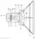
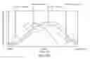
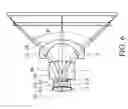
Operation of a camera scanner is more efficient than that of a conventional contact type scanner which reads images line-by-line. Referring to FIG. 1, a conventional camera scanner 1 comprises a housing 11, a lens module 12 disposed in the housing 11, and a light source 13. Light is emitted from the light source 13 to a document 14 and into the housing 11. Subsequently, light is reflected by several mirrors 15 to the lens module 12, thus projecting an image in the lens module 12.
Referring to FIG. 2, the viewing angle θ0 of the camera scanner 1 is about 40 degrees. Because the lens module 12 requires greater focal length to provide adequate viewing angles, dimensions of the camera scanner 1 must be large. To facilitate miniaturization of the camera scanner 1, adequate viewing angles of the lens module 12 must be achieved without large dimensions of the camera scanner 1.
BRIEF SUMMARY OF INVENTION
The application provides a lens module of a scanner, including a first lens with a positive diopter, a second lens with a negative diopter, a third lens with a positive diopter, and a fourth lens with a negative diopter. The first, second, third, and fourth lenses are sequentially arranged from an object end to an image end of the lens module, and at least one of the first and fourth lenses is an aspheric lens. The fourth lens has a focal length f4 and an objective side surface with a radius of curvature R7, wherein 0.1<R7/f<1.
BRIEF DESCRIPTION OF DRAWINGS
The invention can be more fully understood by reading the subsequent detailed description and examples with references made to the accompanying drawings, wherein:
FIG. 1 is a sectional view of a conventional camera scanner;
FIG. 2 is a perspective diagram of a conventional lens module of a scanner;
FIG. 3 is a perspective diagram of a lens module of a scanner according to a first embodiment of the invention;
FIGS. 4A-4D are curvature of image field, distortion, MTF, and through-focus MTF plots according to the first embodiment of the invention;
FIG. 5 is a perspective diagram of a lens module of a scanner according to a second embodiment of the invention; and
FIG. 6 is a perspective diagram of a lens module of a scanner according to a third embodiment of the invention.
DETAILED DESCRIPTION OF INVENTION
First Embodiment
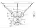
FIG. 3 illustrates a lens module of a scanner according to a first embodiment of the invention. The lens module comprises a first lens 2, a second lens 3, an aperture stop 4, a third lens 5, and a fourth lens 6 sequentially arranged from an object end to an image end. Light passes through the lens module and a cover glass 7 to an image sensor 8 (such as CCD or CMOS), thus capturing images of an object.
In this embodiment, the diopter values of the first and third lenses 2 and 5 are positive, and the diopter values of the second and fourth lenses 3 and 6 are negative to reduce axial chromatic aberration. The first lens 2 is a biconvex glass lens providing main refraction for image formation. The second lens 3 is a biconcave spherical glass lens, and the third lens 5 is a biconvex spherical glass lens to reduce chromatic aberration. The aperture stop 4 is disposed between the second and third lenses 3 and 5, as a middle diaphragm to increase the viewing angle θ. The fourth lens 6 is a negative meniscus glass lens to increase the viewing angle θ and correct field curvature and coma aberration. The first, second, third, fourth lenses 2, 3, 5, 6 and the aperture stop 4 are arranged with a lower limited viewing angle of 80 degrees. The fourth lens 6 satisfies the following condition (1):
0.1<R7/f4<1 (1)
In the condition (1), R7 is the radius of curvature of the object side surface S7 of the fourth lens 6, and f4 is the focal length of the fourth lens 6. When the radius of curvature R7 exceeds the focal length f4 of the fourth lens 6 (R7/f4>1), chromatic aberration may adversely occur. When the focal length f4 is much less than the radius of curvature f4 (R7/f4<0.1), obvious chromatic aberration may occur.
Additionally, the lens module of the scanner satisfies the following condition (2):
0.2<f1/f<1 (2)
In the condition (2), f1 is the focal length of the first lens 2, and f is the system focal length of the lenses module of the scanner. When the focal length f1 exceeds the system focal length f (f1/f>1), the positive diopter value of the first lens 2 is inadequate and results in a long total track length (TTL) of the lens module. When the focal length f1 is much less than the system focal length f (f1/f<0.2), obvious chromatic aberration may occur.
The aspheric surface can be described by the following equation:
z = ch 2 1 + [ 1 - ( k + 1 ) c 2 h 2 ] 1 2 + Ah 4 + Bh 6 + Ch 8 + Dh 10 + Eh 12 + Fh 14 + Gh 16
With respect to the equation, h is the coordinate along the optical axis from an apex of the aspheric surface, z is the vertical distance to the optical axis, k is the conic coefficient, c is the inverse of the radius of curvature, and A-G are aspheric coefficients. The aspheric lenses can have better imaging quality than the spherical lenses. Additionally, since traditional spherical lenses need a large space for accommodating hybrid lenses, total track length thereof is inevitably increased. With the first, second, third, and fourth lenses 2, 3, 5, and 6 satisfying the conditions (1) and (2), the viewing angle θ and clarity of images are efficiently improved.
Table 1-1 illustrates the design data of the lens module of a scanner in accordance with FIG. 3:
| TABLE 1-1 | ||||
| Radius of | Refraction | Abbe | ||
| Surface | curvature (mm) | Thickness (mm) | index (Nd) | number (νd) |
| S1 | 0.641967 | 0.221381 | 1.6691 | 55.4183 |
| S2 | −1.9732 | 0.002621 | ||
| S3 | −1.23195 | 0.039738 | 1.6477 | 33.7928 |
| S4 | 0.638318 | 0.025963 | ||
| Aperture | 0.002928 | |||
| stop | ||||
| S5 | 0.909516 | 0.447511 | 1.7725 | 49.5984 |
| S6 | −0.50172 | 0.171396 | ||
| S7 | −0.16431 | 0.12125 | 1.5481 | 45.7843 |
| S8 | −0.3968 | 0.248175 | ||
As shown in FIG. 3, the lens surfaces S1-S8 are sequentially positioned from an object end to an image end of the lens module. In this embodiment, the lens module has a system focal length f=1 mm, the first lens 2 has a focal length f1=0.7453 mm, the fourth lens 6 has a focal length f4=−0.6239 mm, and the objective side surface S7 has a radius of curvature R7=−0.16431 mm, satisfying the conditions (1) and (2), wherein the viewing angle θ is 82.9 degrees.
Table 1-2 illustrates the design data of the first and fourth aspheric lenses 2 and 6 in accordance with FIG. 3:
| TABLE 1-2 | ||||||||
| Surface | k | A | B | C | D | E | F | G |
| S1 | 2.433773 | −2.2327 | −57.7025 | 3633.602 | −156924 | 3736347 | −4.6E+07 | 2.36E+08 |
| S2 | −7.86902 | −0.75955 | −105.755 | 21279.77 | −1580334 | 81786587 | −3.4E+09 | 7.99E+10 |
| S7 | −1.32484 | 6.398447 | −248.263 | 3842.722 | −80017.5 | 1188408 | −1.2E+07 | 49466170 |
| S8 | −4.23648 | 6.152477 | −59.7664 | −216.965 | 1568.939 | −21113.6 | 90253.07 | −140577 |
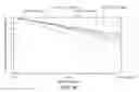
Referring to FIG. 4A, T and S respectively represents curvature of image field of the meridional plane and the sagittal plane at different heights, wherein the horizontal axis represents aberration from the imaging point to the ideal image, and the vertical axis represents ideal height of the image. FIG. 4B illustrates distortion with horizontal magnification, wherein the horizontal axis represents aberration in percentage, and the vertical axis represents ideal height of the image. As shown in FIGS. 4A and 4B, distortion and curvature of the image field are not serious.
FIG. 4C is a modulation transfer function (MTF) diagram which illustrates modulus of the optical transfer function (OTF) response to spatial frequency. FIG. 4D is a through-focus MTF plot showing relationship of the modulus of the optical transfer function (OTF) to the focus shift. As shown in FIGS. 4A and 4D, the lens module in this embodiment can have high optical resolution.
Second Embodiment
Table 2-1 illustrates the design data of the lens module of a scanner in accordance with FIG. 5:
| TABLE 2-1 | ||||
| Radius of | Refraction | Abbe | ||
| Surface | curvature (mm) | Thickness (mm) | index (Nd) | number (νd) |
| S1 | 0.4709 | 0.0692 | 1.6691 | 55.4183 |
| S2 | −1.7122 | 0.0053 | ||
| S3 | −0.7509 | 0.0806 | 1.6477 | 33.7928 |
| S4 | 0.6575 | 0.012 | ||
| Aperture | 0.0178 | |||
| stop | ||||
| S5 | 0.7486 | 0.3176 | 1.7725 | 49.5984 |
| S6 | −1.07 | 0.2255 | ||
| S7 | −0.2476 | 0.0732 | 1.5407 | 47.2271 |
| S8 | −0.7062 | 0.249 | ||
In this embodiment, the lens module has a system focal length f=1 mm, the first lens 2 has a focal length f1=0.6243 mm, the fourth lens 6 has a focal length f4=−0.6535 mm, and the objective side surface S7 of the fourth lens 6 has a radius of curvature R7=−0.2476 mm, satisfying the conditions (1) and (2), wherein the viewing angle θ is 87.28 degrees.
Table 2-2 illustrates the design data of the first and fourth aspheric lenses 2 and 6 in accordance with FIG. 5:
| TABLE 1-2 | ||||||||
| Surface | k | A | B | C | D | E | F | G |
| S1 | 0 | −4.64822 | −62.3516 | 301.8871 | 35514.6 | 0 | 0 | 0 |
| S2 | 0 | −7.31876 | 45.06084 | −456.386 | −19010.1 | 0 | 0 | 0 |
| S7 | 0 | −11.6479 | 36.94115 | −1830.67 | 117423.5 | −554115 | −4.5E+07 | 5.92E+08 |
| S8 | 0 | −8.94015 | 75.04427 | −107.536 | −2081.12 | −11460.2 | 273279.6 | −970782 |
Third Embodiment
Table 3-1 illustrates the design data of the lens module of a scanner in accordance with FIG. 6:
| TABLE 3-1 | ||||
| Radius of | Refraction | Abbe | ||
| Surface | curvature (mm) | Thickness (mm) | index (Nd) | number (νd) |
| S1 | 0.4439 | 0.0706 | 1.6691 | 55.4183 |
| S2 | −2.1998 | 0.0052 | ||
| S3 | −0.9247 | 0.0912 | 1.6477 | 33.7928 |
| S4 | 0.4949 | 0.012 | ||
| Aperture | 0.018 | |||
| stop | ||||
| S5 | 0.8286 | 0.3126 | 1.7725 | 49.5984 |
| S6 | −0.9472 | 0.3017 | ||
| S7 | −0.2078 | 0.0579 | 1.5407 | 47.2271 |
| S8 | −0.4035 | 0.249 | ||
In this embodiment, the lens module has a system focal length f=1 mm, the first lens 2 has a focal length f1=0.5559 mm, the fourth lens 6 has a focal length f4=−0.7423 mm, and the objective side surface S7 of the fourth lens 6 has a radius of curvature R7=−0.2078 mm, satisfying the conditions (1) and (2), wherein the viewing angle θ is 87.92 degrees. According to the first, second and third embodiments, the viewing angle θ increases with the decrease of the focal length f1 of the first lens 2 and the increase of the focal length f4 of the fourth lens 6.
Table 3-2 illustrates the design data of the first and fourth aspheric lenses 2 and 6 in accordance with FIG. 6:
| TABLE 3-2 | ||||||||
| Surface | k | A | B | C | D | E | F | G |
| S1 | 1.247433 | −5.10855 | −52.22 | −848.06 | −4118.9 | 0 | 0 | 0 |
| S2 | −59.3333 | −5.37631 | 48.35064 | −1416.62 | 17458.27 | 0 | 0 | 0 |
| S7 | −0.49138 | 2.143775 | −118.226 | 3637.865 | −39917.3 | 905734.6 | −1.8E+07 | 1.24E+08 |
| S8 | −5.68363 | −8.36629 | 52.43218 | −129.312 | 2683 | −19101.5 | 226118.6 | −507593 |
Since the first, second, third, and fourth lenses 2, 3, 5, and 6 satisfy the conditions (1) and (2), wider viewing angle θ and shorter total track length can be achieved. Additionally, since the first and fourth lenses 2 and 6 are aspheric lenses, distortion and curvature of an image field can be efficiently suppressed.
While the invention has been described by way of example and in terms of preferred embodiment, it is to be understood that the invention is not limited thereto. To the contrary, it is intended to cover various modifications and similar arrangements (as would be apparent to those skilled in the art). Therefore, the scope of the appended claims should be accorded the broadest interpretation to encompass all such modifications and similar arrangements.
Claims
What is claimed is:1. A lens module of a scanner, comprising:
a first lens with a positive diopter;
a second lens with a negative diopter;
a third lens with a positive diopter;
a fourth lens with a negative diopter, wherein the first, second, third, and fourth lenses are sequentially arranged from an object end to an image end of the lens module, at least one of the first and fourth lenses is an aspheric lens, and the fourth lens has a focal length f4 and an objective side surface with a radius of curvature R7, wherein 0.1<R7/f4<1.
2. The lens module as claimed in claim 1, wherein the first and fourth lenses are aspheric lenses.
3. The lens module as claimed in claim 2, wherein the first lens has a focal length f1, and the lens module has a system focal length f, wherein 0.2<f1/f<1.
4. The lens module as claimed in claim 3, wherein the lens module further comprises an aperture stop disposed between the second and third lenses.
5. The lens module as claimed in claim 4, wherein the first, second, third, fourth lenses, and the aperture stop are arranged with a lower limited viewing angle of 80 degrees.
Images & Drawings included:


Sources:
- United States Patent and Trademark Office - verify current appl. status at the USPTO↗
Recent applications in this class:
- » 20250013022 2025-01-09
OPTICAL IMAGING LENS - » 20240184086 2024-06-06
Rear Adapter for a High Etendue Modular Zoom Lens - » 20230043860 2023-02-09
Ultra-short focus projecting optical system and projection device - » 20220252849 2022-08-11
ADJUSTABLE OPTICAL SYSTEM FOR INTRAOCULAR MICRO-DISPLAY - » 20220179182 2022-06-09
High etendue finite conjugate zoom lens assembly with five doublets two movable lens groups - » 20220179181 2022-06-09
High etendue modular zoom lens assembly - » 20210072522 2021-03-11
High Etendue Lens Assembly with Large Zoom Range - » 20210072521 2021-03-11
High etendue zoom lens having movable lens groups between static lens groups - » 20210048653 2021-02-18
High etendue modular lens assembly with afocal zoom having five lens groups - » 20210026118 2021-01-28
High etendue modular zoom lens for machine vision having five lens groups
Recent applications for this Assignee:
- » 20240361104 2024-10-31
AIMING DEVICES AND METHODS THEREOF - » 20230288683 2023-09-14
Optical system - » 20230194256 2023-06-22
Range finder and lens assembly for display thereof - » 20230047206 2023-02-16
Lens device capable of operation of multi-magnifications, optical zoom in high magnification, and miniaturization of the lens module thereof - » 20230018568 2023-01-19
Lens Device - » 20220413278 2022-12-29
Compensating mechanism - » 20220390812 2022-12-08
Lens driving devices and driving methods thereof - » 20220390722 2022-12-08
WIDE-ANGLE LENS ASSEMBLY - » 20220373296 2022-11-24
Sight and compensating mechanism thereof - » 20220357564 2022-11-10
Optical device