Method for deriving shape information
US20110059413A1
2011-03-10
12/596,829
2008-04-18
✅ Patent granted
US 9,439,608 B2
2016-09-13
WO; PCT/EP2008/003135; 20080418
WO; WO2008/128720; 20081030
Cris L Rodriguez | Mirayda A Aponte
Knobbe Martens Olson & Bear, LLP
2030-09-21
Abstract:
A method for deriving shape information of a person's skull and dentition, comprising the steps of: taking an impression of the person's dentition, taking a first scan of the person's head, while the person is wearing the impression, taking a second scan of the impression alone, combining the scans, deriving the shape information from the combined scans. Advantageously the method further comprises the step of taking a third scan of the person's head alone without the impression.
Inventors:
- Gwen Swennen 2 🇧🇪 Knokke-Heist, Belgium
- Filip Schutyser 7 🇧🇪 Sint-Niklaas, Belgium
- Pieter De Groeve 1 🇧🇪 Brussel, Belgium
- Tinne Van Delm 1 🇧🇪 Beerse, Belgium
- Wouter Mollemans 1 🇧🇪 Mechelen, Belgium
- Kevin Suestens 1 🇧🇪 Bonheiden, Belgium
- Nasser Nadjmi 1 🇧🇪 Antwerpen, Belgium
- Pieter De Groeve 1 🇧🇪 Brussels, Belgium
Assignee:
- MEDICIM N.V. 6 🇧🇪 Mechelen, Belgium
Applicant:
Interested in similar patents?
Get notified when new applications in this technology area are published.
Classification:
A61B34/10 » CPC further
Computer-aided surgery; Manipulators or robots specially adapted for use in surgery Computer-aided planning, simulation or modelling of surgical operations
A61C7/14 IPC
Orthodontics, i.e. obtaining or maintaining the desired position of teeth, e.g. by straightening, evening, regulating, separating, or by correcting malocclusions; Brackets; Arch wires; Combinations thereof; Accessories therefor Brackets ; Fixing brackets to teeth
A61B5/1077 » CPC further
Measuring for diagnostic purposes ; Identification of persons; Detecting, measuring or recording devices for testing the shape, pattern, colour, size or movement of the body or parts thereof, for diagnostic purposes; Measuring physical dimensions, e.g. size of the entire body or parts thereof Measuring of profiles
A61B5/4547 » CPC further
Measuring for diagnostic purposes ; Identification of persons; For evaluating or diagnosing the musculoskeletal system or teeth; Evaluating a particular part of the muscoloskeletal system or a particular medical condition; Evaluating the mouth, e.g. the jaw Evaluating teeth
A61B5/4504 » CPC further
Measuring for diagnostic purposes ; Identification of persons; For evaluating or diagnosing the musculoskeletal system or teeth Bones
A61C9/0046 » CPC further
Impression cups, i.e. impression trays ; Impression methods; Means or methods for taking digitized impressions Data acquisition means or methods
A61C9/00 IPC
Dental prosthetics; Artificial teeth
A61C9/00 IPC
Impression cups, i.e. impression trays ; Impression methods
A61B17/666 » CPC further
Surgical instruments, devices or methods, e.g. tourniquets; Surgical instruments or methods for treatment of bones or joints; Devices specially adapted therefor for osteosynthesis, e.g. bone plates, screws, setting implements or the like for external osteosynthesis, e.g. distractors, contractors compression or distraction mechanisms Alignment for jaw bones, e.g. subcutaneous distractors with external access for alveolar distraction
A61B17/80 » CPC further
Surgical instruments, devices or methods, e.g. tourniquets; Surgical instruments or methods for treatment of bones or joints; Devices specially adapted therefor for osteosynthesis, e.g. bone plates, screws, setting implements or the like; Internal fixation devices, including fasteners and spinal fixators, even if a part thereof projects from the skin Cortical plates, i.e. bone plates; Instruments for holding or positioning cortical plates, or for compressing bones attached to cortical plates
A61C19/05 » CPC further
Dental auxiliary appliances; Measuring instruments specially adapted for dentistry for determining occlusion
A61C3/00 IPC
Dental tools or instruments
A61B5/107 IPC
Measuring for diagnostic purposes ; Identification of persons; Detecting, measuring or recording devices for testing the shape, pattern, colour, size or movement of the body or parts thereof, for diagnostic purposes Measuring physical dimensions, e.g. size of the entire body or parts thereof
A61B5/00 IPC
Measuring for diagnostic purposes ; Identification of persons
A61B17/66 IPC
Surgical instruments, devices or methods, e.g. tourniquets; Surgical instruments or methods for treatment of bones or joints; Devices specially adapted therefor for osteosynthesis, e.g. bone plates, screws, setting implements or the like for external osteosynthesis, e.g. distractors, contractors compression or distraction mechanisms Alignment
A61B6/14 » CPC main
Apparatus for radiation diagnosis, e.g. combined with radiation therapy equipment Applications or adaptations for dentistry
Description
FIELD OF THE INVENTION
The present invention relates to methods for assessing the shape of the skull and dentition that are applicable in the field of orthognathic surgery.
BACKGROUND OF THE INVENTION
In maxillofacial surgery, the skull and dentition is surgically remodelled or restored. This surgical discipline encompasses surgical interventions of repair, in particular, of a mis-positioning of the jaws with respect to one another, called orthognathic surgery. Typically, orthognathic surgery involves osteotomies of the maxilla and/or mandible to reposition these bone fragments correctly with respect to the rest of the skull and to create a good occlusion. Osteotomies are surgical operations whereby a bone is cut to shorten, lengthen or change its alignments. With ‘occlusion’ is meant the manner in which the teeth from upper and lower arches come together when the mouth is closed.
Today's procedure to prepare orthognathic surgery mainly consists of the following steps:
-
- 1. Acquisition of 2D cephalograms and performing measurements on them (the latter process is called ‘tracing the 2D cephalogram’),
- 2. Measuring critical distances directly on the patient's face,
- 3. Taking impressions of the upper and lower dental arch in order to produce plaster casts of the dentition. Taking a wax bite registration in order to relate the plaster casts of the upper and lower dentition in order to know the actual occlusion of the patient and to install the casts in an articulator,
- 4. Based on the results of step 1 and 2, and on additional information derived of a clinical evaluation of the patient, the plaster models are repositioned in order to optimize the occlusion. The plaster models might be cut during this step.
- 5. A new facial lateral profile is estimated and drawn on top of the traced 2D cephalogram.
- 6. An acrylic surgical splint is manually created in order to be able to do the same repositioning of the dental arches during surgery.
With the emergence of 3D technologies, methods to carry out the measurement virtually in three dimensions have been established. As a data input, single or multi-slice CT scans were originally applied. With the emergence of cone-beam CT imaging (CBCT) for dental application, acquisition of 3D scan data becomes common sense in the field.
However, no system is available that visualizes the dentition of the patient in a detailed way using a protocol that is clinically feasible without distorting the facial soft tissues. Such a system would allow detailed occlusion planning possibly even including prediction of soft tissue implication and offer the possibilities to create intra-operative tools to establish the planned solution and to maintain it postoperatively.
WO 2006/000063 describes a method to perform a 3D cephalometric analysis of hard and soft tissues and to derive anatomically relevant movements to reposition bone fragments. It also mentions the possibility to enhance the visualization by fusing a scan of plaster models on the basis of a 3D splint with equipped with at least four markers. An important drawback of said approach is that the 3D splint always disturbs the facial profile.
WO 03/028577 describes a method to generate a surgical splint. The key component in this method is the usage of some markers relative to the patient's dentition identifiable in both the digital dental computer model and the computed tomography computer model to visualize the patient's dentition in detail. The registration method is based on point-based matching. However, this method has as fundamental drawback that the markers are disturbing the natural facial expression during the patient scan. This method to create a visualization of the dentition can be seen as a straightforward extension of the work in the field of dental implant planning (see e.g. ‘An image-guided planning system for endosseous oral implants’, Verstreken et al., IEEE Trans Med Imaging 1998, 17, pp. 842-852).
U.S. Pat. No. 6,152,731 describes a method for using digital dental models in a digital articulator. It is a digital analogue for the traditional articulator with plaster dental casts. However, this method has as fundamental drawback that the relationship with the anatomy of the patient's head is lost since only the teeth are visible.
AIMS OF THE INVENTION
The present invention aims to provide a method to derive information from an augmented skull model that offers a detailed visualization of the dentition whereby the use of markers is avoided. In a second aspect the invention aims to provide a method for deriving orthognathic planning information. A further aim of the invention is to provide methods for producing intra- and postoperative tools wherein said method to derive information is applied.
SUMMARY OF THE INVENTION
The present invention relates to a method for deriving shape information of a person's skull and dentition, comprising the steps of:
-
- taking an impression of the person's dentition,
- taking a first scan of the person's head, while the person is wearing the impression,
- taking a second scan of the impression alone,
- combining the scans,
- deriving the shape information from the combined scans.
A major advantage of the method of the present invention is that it is easily applicable in clinical practice and offers the possibility to image the soft tissues in their natural positions. Even more importantly, the method of the invention avoids the need for any fiducial marker (as in WO 03/028577) which yields the substantial advantage that the facial soft tissues are not distorted while performing the method.
Preferably the step of taking the impression is performed with a predefined occlusion.
In a preferred embodiment the method further comprises the step of taking a third scan of the person's head alone without the impression. In that case said step of taking the first scan is performed with a dose less than 45 μSv. The third scan comprises the person's maxillofacial complex. The third scan is taken with a predefined occlusion and facial expression.
Advantageously the second scan is taken with said impression being positioned on a foam-like material. The step of taking the impression is preferably performed with alginate or silicone as impression material. The impression may be taken by means of a wax-bite. In an advantageous embodiment the impression of the person's dentition is a double-sided impression. Preferably the step of taking the impression is performed in a CT scanner.
In a preferred embodiment the method further comprises the step of computing the mandibular autorotation.
In a second aspect the invention relates to a method for deriving orthognathic planning information for repositioning a bone fragment wherein information of a person's skull and dentition is derived with the method as previously described.
The invention further relates to a method for designing and producing an intraoperative splint for transferring a planned occlusion to the surgical field, wherein the splint is designed according to shape information derived from the method as set out above.
The invention also relates to a method for designing and producing a fixation structure for connecting upper and lower dentition, such that a planned occlusion is can be transferred, whereby said fixation structure is designed according to shape information derived from the method for deriving shape information as described. The fixation structure advantageously comprises a set of dental brackets on the lower and upper dentition and a structure for connecting said brackets together in such a way that the planned occlusion is transferred.
In yet another aspect the invention relates to a method for designing and producing customised osteosynthesis plates, designed according to shape information derived from the method as previously described.
The invention further presents a method for designing and producing a postoperative retention tool for preserving a surgically achieved setting, whereby shape information is applied, derived with the method as above described.
The invention also relates to a software program, executable on a programmable device containing instructions, which when executed, perform any of the methods as described.
BRIEF DESCRIPTION OF THE DRAWINGS
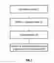
FIG. 1 represents the data flow of the double scan procedure.
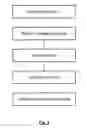
FIG. 2 represents the data flow of the triple scan procedure.
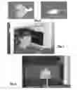
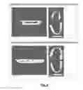
FIG. 3 represents an example of a double sided impression.
FIG. 4 represents the step of taking a scan of the patient's dentition while he is wearing the impression.
FIG. 5 represents a scan setup for the high resolution scan of the impression.
FIG. 6 represents a scan setup for the optional scan of the patient's maxillofacial complex with the occlusion that the doctor wants to examine.
FIG. 7 represents an example of a wax-bite.
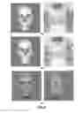
FIG. 8 represents the result of an augmented model. FIG. 8a shows the data of the patient scan. FIG. 8b shows the data of the patient scan with the detailed surface of the dentition. FIG. 8c shows the model of FIG. 8b with the textured skin surface.
FIG. 9 represents the method to optimize the occlusion by repositioning of the jawbones.
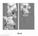
FIG. 10 represents the digital design of a splint based on the planning on the augmented model. An intermediate splint can be designed in a similar way.
FIG. 11 represents the produced splint for the planning shown in FIG. 10.
FIG. 12 represents the produced splint for the planning shown in FIG. 10.
DETAILED DESCRIPTION OF EMBODIMENT(S)
To plan orthognathic surgery and to perform orthognathic surgery according to the planning three main clinical requirements are obvious:
-
- 1. Detailed visualization of the patient's dentition combined with image data of the head and optionally with segmented surfaces out of this image volume. This data set is called an augmented model.
- 2. Easy and fast planning tool to optimize the occlusion, but also the overall skeletal relationships and soft tissue harmony,
- 3. Effective intraoperative support to perform surgery as planned.
Possibly postoperative devices to maintain the surgically achieved solution may be needed.
To meet these clinical requirements, technical requirements are derived:
-
- 1. Image acquisition protocol allowing for detailed visualization of dentition, optionally without disturbing the soft tissue profile
- 2. Appropriate tools to move bone fragments into the right occlusion, preserving the skeletal and soft tissue harmony
- 3. Tools to design and visualize the ideal skin surface for the patient. This ideal skin surface is a target skin surface for simulation. With tools to simulate soft tissue deformation based on bone fragment movements, on soft tissue surgery, on bone fragment sculpting, on implant insertion, etc. . . . , it is checked how well the ideal skin surface can be approximated. Alternatively, movements of bone fragments can be computed to meet the ideal skin surface.
- 4. Generation of intra-operative tools to perform surgery as planned, and optionally postoperative tools to maintain the surgical result.
Furthermore, economical requirements are defined:
-
- 1. The patient handling to obtain the augmented model should be straightforward and fast (this means at least as fast as traditional impression taking and plaster model production and handling),
- 2. The generation of the surgical (and postsurgical) tools needs to be a (semi-) automatic and cheap procedure.
The present invention features all these requirements.
The proposed image acquisition protocol supports the generation of an augmented model possibly without the soft tissue deformation, without the need to position markers, in a fairly easy and realistic clinical setting. The usage of plaster casts of the patient's dentition is not necessary anymore.
The planning protocol extends the anatomically relevant movements of bone fragments with occlusal planning optimization based on the augmented model. Optionally it includes soft tissue simulation and the design of an ideal 3D soft tissue profile.
Next, these planning results are transferred to the operative field by means of a computer-generated surgical splint, or an anchorage system between the brackets on the upper and lower dental arch, or by customized osteosynthesis plates.
Possibly postoperative tools are generated to preserve the surgical result.
The patient can be imaged in two ways: without preservation of the soft tissues in natural rest position (the so-called double-scan procedure) (see FIG. 1), or with preservation of the soft tissues in natural rest position (the so-called triple-scan procedure) (see FIG. 2).
The double-scan procedure is now described. First an impression of the patient's dentition is produced (see (1) in FIG. 1). Preferably, this impression contains a double-sided impression. It contains the shape information of upper and lower dental arches. As an impression material, all dental impression materials (such as alginate, silicone, . . . among others) or rather thick wax-bites (possibly mixed with barium-sulphate to increase the CT-number (i.e. the gray value)) are applicable. The impression materials can be applied in a double impression tray (see FIG. 3). Wax-bites can be modelled on their own (see FIG. 7). Ideally, the gray values of the impression material are different from those of soft tissues so that the impression can be differentiated from the soft and hard tissues. In the double-scan procedure, it is advantageous that the occlusion of the impression is well controlled and corresponds to the clinically desired occlusion for orthognathic surgery planning.
Next the patient is scanned while wearing the impression (see (2) in FIG. 1). The region of interest of the patient's head is scanned. Ideally, the step of impression taking (step 1 in FIG. 1) is performed in the CT-scanner. In this case, the patient does not need to bite twice in the same impression (as it would be difficult to bite a second time in exactly the same way in the impression). It should be carefully checked that the impression completely covers the cuspids of all teeth.
Further, a second high-resolution scan of the impression alone is acquired (see step (4) in FIG. 1 and the illustration in FIG. 5). For reasons of segmentation, the impression should ideally show itself on the CT image data as if it was flying in the air. To accomplish this, the impression can for example be positioned on a foam-like material, such as a sponge.
The various scans are then combined in the following way (step (6) in FIG. 1):
-
- 1. Voxel-based rigid registration (i.e. alignment of position and orientation) of the impression scan (4) to the patient+impression scan (2),
- 2. Image fusion of the detailed impression scan (4) to the maxillofacial complex scan to obtain the augmented model.
Voxel-based rigid registration methods optimize a functional measuring the similarity of all geometrically corresponding voxel pairs for some feature. The voxel-based rigid registration method can be performed by maximization of mutual information, as explained in the paper ‘Multimodality image registration by maximization of mutual information’ (Maes et al., IEEE Trans. Medical Imaging, vol. 16, no. 2, pp. 187-198, April 1997).
The image fusion of the scans can be done using surface models extracted from these scans, or within the image volume, or by a combination of both.
In a preferred embodiment the method as set out above comprises an additional step, typically carried out between the steps (2) and (4) of FIG. 1. Step (2) is thereby slightly modified. The data flow scheme of FIG. 2 is then obtained. This is called the triple-scan procedure.
Now during step (1), the occlusion while biting into the impression material is not important and can be randomly chosen. Technically, also single sided impressions could be applied. However this would require an extra patient scan in a further step, which needs to be avoided as much as possible from a clinical point of view.
Step 2 is a scan of the patient wearing the impression (see (2) in FIG. 2). A very low dose scan of the dentition is enough (see FIG. 4) given that this scan only yields intermediate results. This very low dose can be understood as less than 45 μSv. Ideally, the step of impression taking (Step 1 in FIG. 2) is performed in the CT-scanner. In this case, the patient does not need to bite twice in the same impression. It should be carefully checked that the impression completely covers the cuspids of all teeth.
In the additional step, the patient is scanned again, but now without the impression (see (3) in FIG. 2). The region of interest of the head is scanned. This is typically the maxillofacial complex. Special attention is paid to the occlusion of the patient and to the facial expression. The occlusion needs to be the occlusion that the doctor wants to examine. This might be controlled by a physician directly during the scan. Alternatively, it can be controlled by a tiny wax bite guiding the patient into the right occlusion. Also the facial expression needs to be the expression that the doctor wants to analyse. Typically this is a central occlusion and a neutral, relaxed facial expression.
Further, a third high-resolution scan of the impression alone is acquired (see step (4) in FIG. 2 and the illustration in FIG. 5) in the same way as step (4) in FIG. 1
These various scans are then combined in the following way:
-
- 1. Voxel-based rigid registration of the impression scan (4) to the patient+impression scan (2),
- 2. Voxel-based rigid registration of the upper jaw of the patient+impression scan (2) to the upper jaw in the patient scan (3),
- 3. Voxel-based rigid registration of the lower jaw of the patient+impression scan (2) to the lower jaw in the patient scan (3),
- 4. Image fusion of the detailed impression scan (4) into the maxillofacial complex scan to obtain the augmented model.
Voxel-based rigid registration methods optimize a functional that measures the similarity of all geometrically corresponding voxel pairs for some feature. The voxel-based rigid registration method can be performed by maximization of mutual information, as already mentioned.
The image fusion of the scans can be done using surface models extracted from these scans, or within the image volume. A combination of both can be envisaged as well.
In the triple-scan procedure, the patient is imaged twice (patient scan and patient+impression scan). In those scans, the patient has a different mouth opening. From these two scans, the rotational axis which defines the movement of the mandible during initial mouth opening and closing can be estimated in the 3D space. This estimated rotational axis can be used for example during the planning of orthognathic surgical procedures: after maxillary impaction surgery the mandible will reposition itself according to this axis. To compute this mandibular movement, first both scans are aligned based on the anatomy of the maxilla. In a second step, the mandible of the second registered scan is aligned with the mandible of the first scan. The alignment can be computed using voxel-based registration, marker-based registration or surface-based registration. The resulting transformation matrix describes the mandibular movement. Out of this transformation matrix, the rotation axis is computed in the 3D space. The initial mouth opening/closing is a rotation around that rotation axis.
As an extra guideline for orthognathic surgery planning, the ideal skin surface based on the current skin surface of the patient can be designed.
A first method to design the ideal skin surface is based on clinical relevant parameters, including functional as well as aesthetic parameters, such as the degree of malocclusion or cephalometric measures, and/or body property parameters (such as body mass index, age, racial properties, gender, etc. . . . ).
A second method to design the ideal skin surface is based on the repositioning of points of the skin surface. These points can be important anatomical landmarks. Based on the new positions of these points, a new skin surface is computed.
As a computational strategy for these methods, a statistical model, based on an extensive database of skin surfaces on a large group of persons, is built. These skin surfaces can be acquired by 3D photography, or extracted from CT or MR imaging. The latter allows also including volumetric data into the statistical model. In this case the relation to the bony structures can also be included in the model. For the first method, the model is parameterized according to said parameters. The initial skin surface is altered according to the changes of the parameter values. For the second method, a statistically relevant skin surface is derived from the initial skin surface adapted according to the repositioned points.
Also a combination of both methods is possible.
The ideal skin surface can be set as a target for surgery planning. In order to evaluate how close the surgical plan meets the ideal skin surface, the differences between both surfaces need to be visualised. This can be done by computing a distance map between both surfaces. Ideally, this distance map is based on the distance between anatomically related points. When the differences between both the ideal skin surface and the expected skin surface are minimal, a pleasing surgical plan is obtained.
Orthognathic Surgery Planning
After virtual osteotomies the bone fragments need to be moved to the correct position. Bone fragments are moved with respect to the other skeletal features, to match a desirable occlusion and to obtain an acceptable facial skin surface.
Typically, a bone fragment (e.g. the maxilla) or a group of bone fragments is moved to the appropriate position using anatomical relevant directions, reference planes and anatomical landmarks. Next, bone fragments are moved to optimize the dental occlusion. In the approach according to the present invention, the bone fragments are moved together by spring forces, taking into account the collisions. This technique is called solid body simulation. Finally, further adjustments of the position of bone fragments or groups thereof can be performed.
While doing so, the soft tissue deformation can be simulated and compared with the ideal skin surface.
Intraoperative Tools
To transfer the virtual planning into the surgical field, several approaches are possible. With the intraoperative tools, the planned occlusion can be transferred to the patient. Possibly also the correct position of the bone fragments (like the maxilla) with respect to the skull base and the ascending ramus of the mandible with respect to the TMJ fossa (TMJ means the temporomandibular joint) can be transferred.
A first method to transfer the virtual planning is to produce a surgical splint based on the digital planning data. The splint is designed from the planning data and produced by rapid prototyping techniques or milling techniques (see FIGS. 10, 11 and 12). This method transfers the correct occlusion.
A second method is to produce a fixation structure that connects the upper and lower brackets or the archbars that are wired to the teeth, in order to create the planned occlusion. This method transfers the correct occlusion.
A third method is to produce personalized osteosynthesis plates. When the osteosynthesis plates are in the correct position and the bone fragments are fixed against these plates, the planned bone fragment positions are obtained during surgery. The plates are entered into the correct position based on anatomical features or based on bone anchors that are positioned before patient scanning and segmented from image data obtained from the patient+impression scan in the double-scan method or from the patient scan in the triple-scan method.
Postoperative Tools
In order to stabilize and preserve the surgical result, a postoperative splint might be needed. Also this personalized part can be produced from the results of the planning software.
The advantages of the proposed approach can be summarised as follows. No plaster casts are needed any more, nor the usage of a 3D splint with markers since a different registration concept is applied. This substantially increases the clinical applicability. Moreover, the invention allows having an accurate visualization of the teeth in combination with a natural soft tissue profile, which is a prerequisite to do correct soft tissue deformation prediction.
Also in the field of the planning process, this improved visualization of the teeth enables accurate occlusion planning and the production of intra- and postoperative tools.
Although the present invention has been illustrated by reference to specific embodiments, it will be apparent to those skilled in the art that the invention is not limited to the details of the foregoing illustrative embodiments, and that the present invention may be embodied with various changes and modifications without departing from the spirit and scope thereof. The present embodiments are therefore to be considered in all respects as illustrative and not restrictive, the scope of the invention being indicated by the appended claims rather than by the foregoing description, and all changes which come within the meaning and range of equivalency of the claims are therefore intended to be embraced therein. In other words, it is contemplated to cover any and all modifications, variations or equivalents that fall within the spirit and scope of the basic underlying principles and whose essential attributes are claimed in this patent application. It will furthermore be understood by the reader of this patent application that the words “comprising” or “comprise” do not exclude other elements or steps, that the words “a” or “an” do not exclude a plurality, and that a single element, such as a computer system, a processor, or another integrated unit may fulfil the functions of several means recited in the claims. Any reference signs in the claims shall not be construed as limiting the respective claims concerned. The terms “first”, “second”, third”, “a”, “b”, “c”, and the like, when used in the description or in the claims are introduced to distinguish between similar elements or steps and are not necessarily describing a sequential or chronological order. Similarly, the terms “top”, “bottom”, “over”, “under”, and the like are introduced for descriptive purposes and not necessarily to denote relative positions. It is to be understood that the terms so used are interchangeable under appropriate circumstances and embodiments of the invention are capable of operating according to the present invention in other sequences, or in orientations different from the one(s) described or illustrated above.
Claims
1. A method for deriving shape information of a person's skull and dentition, comprising:
taking an impression of said person's dentition,
taking a first scan of said person's head, while the person is wearing said impression,
taking a second scan of said impression alone,
combining said scans, and
deriving said shape information from said combined scans.
2. The method for deriving shape information as in claim 1, wherein said taking an impression is performed with a predefined occlusion.
3. The method for deriving shape information as in claim 1, further comprising taking a third scan of said person's head alone without said impression.
4. The method for deriving shape information as in claim 3, wherein said taking an first scan is performed with a dose less than 45 μSv.
5. The method for deriving shape information as in claim 3, wherein said third scan comprises said person's maxillofacial complex.
6. The method for deriving shape information as in claim 3, wherein said third scan is taken with a predefined occlusion and facial expression.
7. The method for deriving shape information as in claim 1, wherein said second scan is taken with said impression being positioned on a foam-like material.
8. The method for deriving shape information as in claim 1, wherein said step of taking an impression is performed with alginate or silicone as impression material.
9. The method for deriving shape information as in claim 1, wherein said taking an impression is performed by means of a wax-bite.
10. The method for deriving shape information as in claim 1, wherein said impression of said person's dentition is a double-sided impression.
11. The method for deriving shape information as in claim 1, wherein said taking an impression is performed in a CT scanner.
12. The method for deriving shape information as in claim 1, further comprising computing the mandibular autorotation.
13. A method for deriving orthognathic planning information for repositioning a bone fragment wherein information of a person's skull and dentition is derived with the method as in claim 1.
14. A method for designing and producing an intraoperative splint for transferring a planned occlusion to the surgical field, wherein said splint is designed according to shape information derived from the method as in claim 1.
15. A method for designing and producing a fixation structure for connecting upper and lower dentition, such that a planned occlusion can be transferred, whereby said fixation structure is designed according to shape information derived from the method as in claim 1.
16. The method for designing and producing a fixation structure as in claim 15, wherein said fixation structure comprises a set of dental brackets on the lower and upper dentition and a structure for connecting said brackets together.
17. A method for designing and producing customized osteosynthesis plates, designed according to shape information derived from the method as in claim 1.
18. A method for designing and producing a postoperative retention tool for preserving a surgically achieved setting, whereby shape information is applied, derived with the method as in claim 1.
19. A program, executable on a programmable device containing instructions, which when executed, performs the method as in claim 1.
Images & Drawings included:
Sources:
- United States Patent and Trademark Office - verify current appl. status at the USPTO↗
Recent applications in this class:
- » 20240245376 2024-07-25
SCANNING DENTAL IMPRESSIONS - » 20240041418 2024-02-08
Systems and methods for processing of dental images - » 20230320680 2023-10-12
X-RAY IMAGING SYSTEM FOR A CEPHALOMETRIC DENTOMAXILLOFACIAL X-RAY IMAGING OPERATION - » 20230301611 2023-09-28
Dental panoramic views - » 20220395240 2022-12-15
Ultra-fast scanning x-ray imaging device - » 20220395239 2022-12-15
Ultra-fast scanning x-ray imaging device - » 20220386971 2022-12-08
X-ray imaging apparatus - » 20220361830 2022-11-17
Method and a system for obtaining operating parameters for x ray data acquisition - » 20220361829 2022-11-17
Method and system for obtaining operating parameters for 3D x ray acquisition - » 20220202382 2022-06-30
Method and apparatus for generating a panoramic layer image
Recent applications for this Assignee:
- » 20220036653 2022-02-03
Automated trimming of a surface mesh - » 20210209764 2021-07-08
Methods, systems, and computer programs for segmenting a tooth's pulp region from an image - » 20200170760 2020-06-04
Method for intraoral scanning directed to a method of processing and filtering scan data gathered from an intraoral scanner - » 20120201443 2012-08-09
Method for digitizing dento-maxillofacial objects - » 20080159608 2008-07-03
Method and system for pre-operative prediction