Crown molding scales for a miter saw
US20110067544A1
2011-03-24
12/923,364
2010-09-16
✅ Patent granted
US 8,776,654 B2
2014-07-15
-
-
Clark F. Dexter
2032-05-15
Abstract:
The invention is comprised of a series of dimensional scales (linear measuring device) on the top surface of a miter saw table. The scales allow for measurements to be located or obtained on the saw table relative to the saw fence and relative to the saw blade. The scales may replace the need for a hand held tape measure or ruler for measuring or marking the saw table surface when cutting crown molding or other materials. The scales could be placed on or in a saw during production by a manufacturer. The scales could be placed on or in a material to be placed on a saw during production by a manufacturer. The scales could be placed on or in a material to be placed on an existing saw.
Applicant:
Interested in similar patents?
Get notified when new applications in this technology area are published.
Classification:
B27G5/02 IPC
Machines or devices for working mitre joints with even abutting ends for sawing mitre joints; Mitre boxes
B23D47/025 » CPC main
Sawing machines or sawing devices working with circular saw blades, characterised only by constructional features of particular parts of frames; of guiding arrangements for work-table or saw-carrier of tables
B23D59/002 » CPC further
Accessories specially designed for sawing machines or sawing devices; Measuring or control devices, e.g. for automatic control of work feed pressure on band saw blade for the position of the saw blade
Y10T83/76 » CPC further
Cutting; With work immobilizer; Work-stop abutment With scale or indicator
Y10T83/762 » CPC further
Cutting; With work immobilizer; Work-stop abutment; Normal to plane of cut; Adjustable Angularly relative to plane of cut; e.g., miter
Y10T83/7697 » CPC further
Cutting; Rotatable disc tool pair or tool and carrier; With means to support work relative to tool[s]; Tool moved relative to work-support during cutting Tool angularly adjustable relative to work-support
Y10T83/849 » CPC further
Cutting With signal, scale, or indicator
Y10T83/857 » CPC further
Cutting; With signal, scale, or indicator; Indicates tool position; Relative to another element; To work-engaging member Calibrated scale or indicator
Y10T83/858 » CPC further
Cutting; With signal, scale, or indicator; Indicates tool position; Relative to another element; To work-engaging member; Calibrated scale or indicator Indicates dimension of work being cut
B26D7/28 IPC
Details of apparatus for cutting, cutting-out, stamping-out, punching, perforating, or severing by means other than cutting; Means for performing other operations combined with cutting for counting the number of cuts or measuring cut lenghts
B23D45/14 IPC
Sawing machines or sawing devices with circular saw blades or with friction saw discs for cutting otherwise than in a plane perpendicular to the axis of the stock, e.g. for making a mitred cut
B23D47/04 IPC
Sawing machines or sawing devices working with circular saw blades, characterised only by constructional features of particular parts of devices for feeding, positioning, clamping, or rotating work
B23Q17/22 IPC
Arrangements for observing, indicating or measuring on machine tools for indicating or measuring existing or desired position of tool or work
B26D7/01 IPC
Details of apparatus for cutting, cutting-out, stamping-out, punching, perforating, or severing by means other than cutting Means for holding or positioning work
B27B5/29 IPC
Sawing machines working with circular or cylindrical saw blades ; Components or equipment therefor Details; Component parts; Accessories
Description
CROSS-REFERENCE TO RELATED APPLICATIONS
This application claims benefits of Provisional Application for Patent No. 61/276/835, filed Sep. 18, 2009, applicant—Timothy J. Glomb Sr., Kennett Square, Pa.
STATEMENT REGARDING FEDERALLY SPONSORED RESEARCH OR DEVELOPMENT
“Not Applicable”
REFERENCE TO A SEQUENCE LISTING, A TABLE, OR A COMPUTER PROGRAM, LISTING COMPACT DISC APPENDIX
“Not Applicable”
BACKGROUND OF THE INVENTION
The invention pertains to an improvement to a miter saw table for locating dimensions on the table. In the art of finish carpentry, specifically moldings and decorative trim work, it is commonly understood that installing crown molding is a difficult and tedious task for professionals and “do-it-yourselfers”. Crown molding is a decorative trim generally seen in a room along the top of the walls where the wall meets the ceiling. The bottom edge of the molding lies against the wall, the top edge of the molding lies against the ceiling and the face of the molding lies at an angle between the wall surface and the ceiling surface. Although this is the most common application of crown molding it can be used elsewhere. The wall/ceiling location of crown molding is the focus of this explanation. A basic room has four walls, so a basic installation of crown molding in a room would have four inside corner joints. An inside corner is where two walls meet and face each other, usually at a 90 degree angle. Concepts explained here may be applied to other molding applications and for outside corner joints. On average there are more inside corner joints than any other joining of the molding. So emphasis may be placed on cutting crown molding for assembling inside corners joints, and emphasis may be placed on the design of tools used for cutting crown molding for assembling inside corner joints.
In the art, it is known, there are two methods of assembling an inside corner joint. The first method is a miter joint. This joint is made by beveling the end of two pieces of crown molding at equal compound angles but alternate directions to be joined at a corner. This method requires exact measuring, cutting and installing. Frequently, a miter joint will not fit properly after the molding is cut. Generally, the compound angle cut is incorrect and the molding piece may not be able to be adjusted or re-cut for use. The installer would have to begin this corner joint with a new piece of molding. The second method of joining an inside corner is a coped joint. A coped joint is completed by installing the first piece of molding on a wall with both ends of the molding cut square to butt against the adjacent walls. The second piece of molding for an adjacent wall is cut on one end (“a coped cut”) to match the profile of the first piece of molding. The coped cut is achieved by beveling a compound angle (“beveled cut”) on the end of the second piece of molding. Using a miter saw, there are two positions to perform the beveled cut for coping, the flat position and the nesting (or stand-up) position.
The flat position uses a compound miter saw. An installer using the flat position would place the molding face up or face down on the saw table and press the edge against the fence, swivel the blade at an angle to the fence, bevel the blade at an angle to the table, and cut the molding. The angles are available from charts and vary on the type of molding used.
The nesting position uses any miter saw that will accommodate the size of the molding. The installer using the nesting position would place the top edge of the molding on the saw table and the bottom edge of the molding against the fence. The back side of the molding will be at a diagonal between the saw table and the saw fence similar to the positions of the wall and ceiling where molding will be installed. With the saw blade perpendicular to the saw table, swivel the blade to 45 degrees for a 90 degree corner and complete the cut. The result will be a bevel cut to the end of this piece of molding. Swiveling the blade left or right would determine whether the molding will fit to the left side or right side of the corner.
Once beveled, the installer using a coping saw would cut off the bevel portion by cutting along the edge of the face of the molding. The installer would cut beyond a perpendicular line to the face of the molding to remove more than the bevel from the backside of the molding. This would allow the second piece of molding to pivot closer to or away from the first piece of molding while still fitting tight at the face. This pivoting would be needed if the original bevel cut was not the exact angle. The pivoting gives the installer the flexibility to fit a tight joint and may be the main reason for using the coping method. Once the bevel is removed, the end of the molding would have the contour of its own profile. When placed on the wall it would fit tightly against the first piece of molding completing the joint. There are other tools available for removing the bevel portion of the molding. It would be the installer's personal preference of the tool used to perform a coped cut.
Frequently, a correct coped cut will not fit properly against the first piece of molding. This is common in the art and generally is due to the imperfections with room construction or the molding, or installer error. If the coped cut was done properly, the most common reason it doesn't fit is because the projection dimension of the first piece of molding on the wall was not the same as the projection dimension of the second piece of molding on the saw table. This has occurred for decades and continues today. Through trial and error the installer eventually gets it to fit, but at the cost of additional labor time and expense and replacement material costs. This can be remedied by using the nesting position and the molding projection dimensions on the miter saw.
The Crown Molding Scales are measuring scales on the miter saw table to allow the installer to quickly transfer the projection dimension of molding on the wall to the projection location on the saw table. It is helpful for the installer to understand that the projection dimension is from where the bottom edge of the molding touches the wall plane to the face of the top edge of the molding. This is used as the projection dimension from the saw fence to place the top edge of the second piece of molding on the saw table. The projection dimension of crown molding is the key element in the process of two pieces being joined in an inside or outside corner. This projection dimension is the same as the dimension on the saw table that the top edge of the molding should be distanced or project from the saw fence to cut the bevel.
The Crown Molding Scales will eliminate the need for and reduce errors caused by hand held tape measures or rulers used to locate the correct dimension on the miter saw table. The Crown Molding Scales may reduce errors caused by hand held tape measures or rulers used to locate the correct dimension on the miter saw table. The Crown Molding Scales offer flexibility as they are fixed unlike hand applied measurements, marks, pieces of tape or other temporary labeling devices placed on the miter saw table. The Crown Molding Scales could be placed on or in a new saw during production by a manufacturer. Or the Crown Molding Scales could be placed on or in a material to be placed on a new or old saw.
BRIEF SUMMARY OF THE INVENTION
-
- The objective of the invention is to provide the means to quickly locate and place material on the accurate location of the miter saw table. The Crown Molding Scales are comprised of a series of dimensional scales on the table of a miter saw. There are scales to provide dimensions on the saw table relative to the saw fence and there are scales to provide dimensions relative to the saw blade at a multitude of angles. The scales are fixed and do not move on the table. The Crown Molding Scales eliminate the need for and reduce errors caused by hand held tape measures or rulers used to locate the correct dimension on the miter saw table. They are beneficial for cutting crown molding, measuring items, and will assist in cutting any material the saw manufacturer recommends. The scales could be placed on or in a new saw during production by a manufacturer. Or the scales could be placed on or in a material to be placed on a new or old saw.
DESCRIPTION OF THE VIEW OF THE DRAWINGS
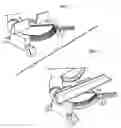
Page 1, FIG. 1 depicts The Crown Molding Scales on a miter saw table and parts of the saw noted as follows;
-
- 1. The front edge of the miter saw table.
- 2. The left side of the fixed portion of the miter saw table.
- 3. The right side of the fixed portion of the miter saw table.
- 4. The rotating portion of the miter saw table.
- 5. The miter saw blade
- 6. The miter saw fence
- 7. A scale on the left fixed portion of the miter saw table measuring perpendicular from the saw fence.
- 8. A scale on the right fixed portion of the miter saw table measuring perpendicular from the saw fence.
- 9. A scale on the rotating portion of the saw table measuring perpendicular from the saw fence when the saw blade is perpendicular to the saw fence. The scale is to the left of the saw blade.
- 10. A scale on the rotating portion of the saw table measuring perpendicular from the saw fence when the saw blade is perpendicular to the saw fence. The scale is to the right of the saw blade
- 11. A scale on the rotating portion of the saw table measuring perpendicular from the saw fence when the saw blade is swiveled to the right at a 22.5 degree angle to the saw fence. The scale is to the left of the saw blade.
- 12. A scale on the rotating portion of the saw table measuring perpendicular from the saw fence when the saw blade is swiveled to the left at a 22.5 degree angle to the saw fence. The scale is to the right of the saw blade.
- 13. A scale on the rotating portion of the saw table measuring perpendicular from the saw fence when the saw blade is swiveled to the right at a 45 degree angle to the saw fence. The scale is to the left of the saw blade.
- 14. A scale on the rotating portion of the saw table measuring perpendicular from the saw fence when the saw blade is swiveled to the left at a 45 degree angle to the saw fence. The scale is to the right of the saw blade.
- 15. A scale on the rotating portion of the saw table measuring perpendicular from the saw blade. The scale is to the left of the saw blade and against the fence when the saw blade is perpendicular to the saw fence.
- 16. A scale on the rotating portion of the saw table measuring perpendicular from the saw blade. The scale is to the right of the saw blade and against the fence when the saw blade is perpendicular to the saw fence.
- 17. The saw blade handle for swiveling the rotating table.
Page 2, FIG. 1 depicts the table of a miter saw.
Page 2, FIG. 2 depicts a piece of crown molding placed in the nesting position on the table of a miter saw.
DESCRIPTION OF THE INVENTION
This invention is comprised of a series of dimensional scales (linear measuring devices) on a miter saw table. This invention will provide the means to allow an installer to quickly locate and accurately place material on the desired location of a miter saw table. In FIG. 1 the front'edge 1 of the miter saw table is for location only. Reference to a saw table would mean the tables of a miter saw and would include both the fixed portions 2 and 3 and the rotating portion 4 of a miter saw table. Reference of the scales would include scales 7, 8, 9, 10, 11, 12, 13, 14, 15 and 16. Scales 7 and 8 are on the fixed portions 2 and 3 respectively of a saw table. Scales 7 and 8 provide dimensions relative to the miter saw fence 6. Scales 9, 10, 11, 12, 13, 14, 15 and 16 are on the rotating portion 4 of a saw table. Scales 9, 10, 11, 12, 13, 14, 15 and 16 provide dimensions relative to the saw fence 6 and saw blade 5 at a plurality of angles on the rotating portion 4 of a saw table. The scales could be placed on or in a saw during production by a manufacturer. The scales could be placed on or in a material to be placed on a saw during production by a manufacturer. The scales could be placed on or in a material to be placed on an existing saw. The scales could be projected by light beam or laser beam onto a saw. The scales eliminate the need for a hand held tape measure or ruler to locate a dimension or place a mark at a specified dimension on a saw table. The scales will reduce errors caused by using a hand held tape measure or ruler to locate a dimension or place a mark at a specified dimension on a saw table. The scales offer flexibility as they are fixed on a saw table unlike hand applied measurements, marks, pieces of tape or other temporary labeling devices placed on a saw table. The scales are for cutting crown molding and cutting any material a saw manufacturer recommends.
This invention is measuring scales on a miter saw table. The projection dimension of crown molding is the key element for cutting two pieces of crown molding being joined in an inside corner or an outside corner. The projection dimension is the distance from the face of a wall where the bottom edge of the molding touches the wall to the face of the top edge of the molding. The nesting position is the placement of a piece of crown molding on the saw table with the bottom edge of the molding against the fence and the top edge of the molding on the table. The face of the molding is at a diagonal between the fence and the table. In this position the projection dimension is the distance the top edge of the molding projects from the fence. The primary use of this invention allows the installer to transfer the projection dimension of crown molding on the wall to the corresponding projection dimension location on the miter saw table.
On drawing page 1, FIG. 1, the scales provide projection dimensions on the saw table as follows:
-
- a. scales 7 and 8 measure perpendicular from the saw fence
- b. with the saw blade perpendicular to the saw fence scales 9 and 10 measure perpendicular from the saw fence and scales 15 and 16 measure perpendicular from the saw blade
- c. with the saw blade swiveled left at 22.5 degrees scale 12 measures perpendicular from the saw fence
- d. with the saw blade swiveled left at 45 degrees scale 14 measures perpendicular from the saw fence
- e. with the saw blade swiveled left at another angle a scale placed at this degree angle would measure perpendicular from the saw fence
- f. with the saw blade swiveled right at 22.5 degrees scale 11 measures perpendicular from the saw fence
- g. with the saw blade swiveled right at 45 degrees scale 13 measures perpendicular from the saw fence
- h. with the saw blade swiveled right at another angle a scale placed at this degree angle would measure perpendicular from the saw fence
- i. scales 7, 8, 9, 10, 11, 12, 13, 14, 15 and 16 can generally measure in relation to the saw fence and the saw blade
- j. scales 7, 8, 9, 10, 11, 12, 13, 14, 15 and 16 can generally measure with no relation to the saw fence and the saw blade
Here is an example which is descriptive only and not an instruction. Proper safety methods should be taken for actual installation. With the scales on a miter saw table, the optimal use of the invention is described in the following example. To join crown molding in an inside corner a user would:
-
- a. Secure the first piece of crown molding on a wall to the left of a 90 degree inside corner. This piece is square cut on end and butts firmly against the adjacent wall.
- b. Measure near the adjacent wall the projection dimension (X) of the first piece of molding.
- c. Swivel the miter saw blade 5 (FIG. 1) to the left at 45 degrees, scale 14 (FIG. 1) is now perpendicular to the saw fence.
- d. Place the top edge of the second piece of molding on the saw table. Place the top edge of the molding on dimension (X) on scale 7 (FIG. 1) and the right hand end of the molding on dimension X on scale 14 (FIG. 1). Lower the saw blade 5 (FIG. 1) to make a bevel cut to prepare the molding for the coping cut.
- e. Using a coping saw, cut off the bevel portion on the end of the second piece of molding. This coped end will now fit against the first piece of molding.
- f. Position the second piece of molding on the wall to the right of the inside corner and slide the coped end firmly against the first piece of molding. Secure the second piece of molding to complete this inside corner joint.
Problems frequently occur using other methods that do not take projection dimension into account in the process of these methods. Mistakes made are costly and generally rectified through time consuming trial and error. The scales facilitate the accuracy necessary to avoid problems caused by any methods.
Claims
What I claim as my invention comprises a plurality of dimensional scales (linear measuring devices) on the fixed (stationary) table and the rotating table of a miter saw:1) I claim the embodiment comprising a plurality of dimensional scales (linear measuring devices) is on,
a. the left side of the fixed portion of a miter saw table,
b. the right side of the fixed portion of a miter saw table, and
c. the rotating portion of a miter saw table.
2) The scales of claim 1 shall increase in measure as
a. the scales project away from the saw fence, and
b. the scales project away from the saw blade.
3) The scales of claim 1 are,
a. placed on or in a saw during production by a manufacturer,
b. placed on or in a material to be placed on a saw during production by a manufacturer, and
c. placed on or in a material to be placed on an existing saw.
4) The scales of claim 1a and 1b are,
a. perpendicular to the saw fence, and
b. begin at the saw fence and increase in measure as the scale projects away from the saw fence.
5) The scales of claim 1c are aligned, when the saw blade is set perpendicular to the fence, that,
a. their measurement begins at the intersect point of the center of the saw blade, the saw fence plane and the saw table plane, or
b. their measurement begins parallel to the intersect point of the saw blade, the saw fence plane or the saw table plane, and
a) are comprised of,
1) a scale on the left side of the blade at any angle to the blade, and
2) a scale on the right side of the blade at any angle to the blade.
6) The scales of claim 1c are aligned, when the saw blade is set perpendicular to the fence, that,
a. their measurement begins at the intersect point of the center of the saw blade, the saw fence plane and the saw table plane, or
b. their measurement begins parallel to the intersect point of the saw blade, the saw fence plane or the saw table plane, and
c. are comprised of,
1) a scale on the left side of the blade at a 90 degree angle to the blade and against the fence plane,
2) a scale on the right side of the blade at a 90 degree angle to the blade and against the fence plane,
1) a scale on the left side of the blade at a 45 degree angle to the blade,
2) a scale on the right side of the blade at a 45 degree angle to the blade,
3) a scale on the left side of the blade at a 22.5 degree angle to the blade,
4) a scale on the right side of the blade at a 22.5 degree angle to the blade,
5) a scale on the left side of the blade, adjacent to and parallel to the blade, and
6) a scale on the right side of the blade, adjacent to and parallel to the blade.
Images & Drawings included:

Sources:
- United States Patent and Trademark Office - verify current appl. status at the USPTO↗
Recent applications in this class:
- » 20250235940 2025-07-24
POWER SAWS - » 20250196239 2025-06-19
Table Saw With Gravity Rise Stand - » 20240399478 2024-12-05
BENCHTOP CIRCULAR SAW APPARATUS WITH INTEGRATED MULTISTAGE FILTRATION SYSTEM - » 20240300040 2024-09-12
Power saws - » 20240058878 2024-02-22
WOOD AND METAL WORKING TOOLS HAVING A LOW FRICTION COATING - » 20230302555 2023-09-28
SAW DEVICE, STACK ARRANGEMENT, COVER ARRANGEMENT, TRANSPORT ARRANGEMENT AND METHOD - » 20230201935 2023-06-29
SAW SUPPORT ASSEMBLY - » 20220395917 2022-12-15
Miter saw - » 20220371111 2022-11-24
Adaptive cutting system - » 20220331888 2022-10-20
Tile saw