HYBRID COMPONENT
US20110070092A1
2011-03-24
12/861,293
2010-08-23
Abstract:
A method for making a hybrid component comprises the steps of placing a lower shell in the lower half of an RTM form tool; placing layers of composite fabric on top of the lower shell to define a composite core; placing an upper shell on top of the layers; closing the RTM form tool; infiltrating the composite fabric with resin; curing the resin. At least one of the lower and upper shells comprises pins projecting generally perpendicularly to its surface, and the pins penetrate the composite fabric.
Assignee:
- ROLLS-ROYCE PLC 4,086 🇬🇧 London, United Kingdom
Interested in similar patents?
Get notified when new applications in this technology area are published.
Classification:
F01D5/147 » CPC main
Blades; Blade-carrying members ; Heating, heat-insulating, cooling or antivibration means on the blades or the members; Blades; Form or construction Construction, i.e. structural features, e.g. of weight-saving hollow blades
B29C70/088 » CPC further
Shaping composites, i.e. plastics material comprising reinforcements, fillers or preformed parts, e.g. inserts comprising reinforcements only, e.g. self-reinforcing plastics; Fibrous reinforcements only comprising combinations of different forms of fibrous reinforcements incorporated in matrix material, forming one or more layers, and with or without non-reinforced layers and with one or more layers of non-plastics material or non-specified material, e.g. supports
B29C70/48 » CPC further
Shaping composites, i.e. plastics material comprising reinforcements, fillers or preformed parts, e.g. inserts comprising reinforcements only, e.g. self-reinforcing plastics; Shaping operations therefor; Shaping or impregnating by compression not applied for producing articles of definite length, i.e. discrete articles using matched moulds, e.g. for deforming sheet moulding compounds [SMC] or prepregs and impregnating the reinforcements in the closed mould, e.g. resin transfer moulding [RTM], e.g. by vacuum
F01D5/282 » CPC further
Blades; Blade-carrying members ; Heating, heat-insulating, cooling or antivibration means on the blades or the members; Blades; Selecting particular materials; Particular measures relating thereto; Measures against erosion or corrosion Selecting composite materials, e.g. blades with reinforcing filaments
B29K2705/00 » CPC further
Use of metals, their alloys or their compounds, for preformed parts, e.g. for inserts
B29L2031/082 » CPC further
Other particular articles; Blades for rotors, stators, fans, turbines or the like, e.g. screw propellers Blades, e.g. for helicopters
Y10T29/49337 » CPC further
Metal working; Method of mechanical manufacture; Impeller making; Blade making Composite blade
Y10T428/23 » CPC further
Stock material or miscellaneous articles Sheet including cover or casing
F04D29/38 IPC
Details, component parts, or accessories; Rotors specially for elastic fluids for axial flow pumps Blades
B32B15/14 IPC
Layered products comprising a layer of metal next to a fibrous or filamentary layer
B23P15/04 IPC
Making specific metal objects by operations not covered by a single other subclass or a group in this subclass turbine or like blades from several pieces
B32B15/00 IPC
Layered products comprising a layer of metal
B29C45/14 IPC
Injection moulding, i.e. forcing the required volume of moulding material through a nozzle into a closed mould; Apparatus therefor incorporating preformed parts or layers, e.g. injection moulding around inserts or for coating articles
Description
This invention relates to hybrid components (that is, those comprising both metal and fibre-reinforced composite), and is particularly applicable to hybrid blades for gas turbine engines in which a core made of composite material is surrounded by an outer shell made of metal.
It is known to make blades, particularly fan blades for gas turbine engines, with a hybrid construction. In one known type of hybrid blade, a composite core (consisting of two-dimensional (2D) or three-dimensional (3D) fibre-reinforced composite material) has a sheet metal protective shell adhesively bonded to it. The shell may cover the whole fan blade (including or excluding the root part) or it may cover only part of it (for example, the leading or trailing edges).
Such a hybrid construction allows the advantages of composite material construction (for example, superior fatigue resistance, high specific strength and the ability to tailor mechanical properties in different directions to match the demands on the blade in use) to be utilised, while the metal shell ameliorates the known disadvantages of composite materials (notably, that their resistance to erosion and impact damage is inferior to that of metal blades).
There are, however, limitations and disadvantages associated with known hybrid blades. For example:
- the adhesive bond between the metal shell and composite core is a weak spot and is prone to debonding under impact;
- the manufacturing process of such a blade must comprise at least two distinct steps (infiltrating the composite core and adhesively bonding the metal shell) and is therefore relatively complex;
- the composite core is prone to delamination unless 3D composite, rather than 2D composite, is used. However, while 3D composites offer better through-thickness properties than 2D composites, their in-plane properties are inferior;
at present, 3D composites are less well understood than 2D composites, and the additional development work needed to use 3D composites in a particular application may outweigh any economic advantage over 2D composites.
A first aspect of the invention provides a method for making a hybrid component as set out in claim 1. A second aspect of the invention provides a hybrid component as set out in claim 8.
To help understanding of the invention and how it may be put into effect, an embodiment thereof will now be described, by way of example, with reference to the accompanying drawings in which:
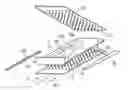
FIG. 1 is a schematic perspective view illustrating a method according to the invention; and
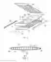
FIG. 2 is a cross-sectional view on the line A-A in FIG. 1.
FIG. 1 illustrates the manufacture of a fan blade for a gas turbine engine in accordance with the invention.
The first step is to place a lower shell 12 into the lower half of a resin transfer moulding (RTM) form tool (not shown) of known type. The lower shell 12 is made of titanium alloy. The lower shell incorporates regularly-spaced metal pins 14, which extend perpendicularly to its surface. The pins are about 1 mm in diameter at the root, and each tapers to a relatively sharp point.
Next, a number of layers 16 of unidirectional composite fabric are successively placed on top of the lower shell, with the pins penetrating the fabric. The layers of fabric may be cut to shape, as in 16b and 16c, so that the layers will together define a composite core of the correct shape to form the fan blade. The layers of fabric also define a root portion 18 of the fan blade.
Next, an upper shell 20 is placed on top of the layers of fabric. The upper shell, like the lower shell, is made of titanium alloy and has regularly-spaced metal pins 22 extending perpendicularly to its surface. The pins penetrate the layers of fabric defining the core. Next, a leading edge cover 24 and a trailing edge cover 26 are fitted so as to overlap the edges of the upper and lower shells. In this way, the infiltrating resin (described below) will also provide the adhesive bond between the covers 24, 26 and the shells 12, 20.
The upper half of the RTM form tool (not shown) is then brought down to close and seal the RTM form. The form is next infiltrated with resin according to known methods, the resin being introduced into the form via the root portion 18, as shown by the arrows 28.
Following infiltration, curing and potentially tempering according to the resin specifications, the product of the method is a fan blade as shown in cross-section in FIG. 2. Features are identified with the same reference numbers as in FIG. 1.
The pins 14, 22 of the respective shells 12, 20 extend through the core 30 of the formed fan blade. This provides a better mechanical bond between the shells and the core than in prior arrangements, reducing the risk of debonding of the structure in service, for example under impact loading. Furthermore, the pins provide the 2D composite core with a third-dimensional reinforcement comparable to Z-pinning; this provides many of the advantages of a 3D composite core while permitting the use of the simpler, and currently more economical, 2D composite.
The invention thus provides an improved method of making a turbomachine blade, the method resulting in an improved product. The method allows the entire blade to be produced in a single operation, in contrast to known methods. Also, it permits the core to be made from unidirectional composite fabric, yet the resulting blade has many of the advantageous properties associated with 3D composite cores.
Because the metal pins extend through and engage with the composite core, the bonding of the shells is much better than in known hybrid blades and there is less risk of debonding in use.
It is known that conventional 3D reinforcement members (such as carbon fibre pins and 3D yarns) offer little resistance to mode II loading, because of their low mechanical properties perpendicular to their fibre direction. The reinforcement effect (especially in terms of dissipated energy) achievable with the metal pins is expected to be superior is because of the isotropic nature of the metal pins and their relatively high strain to failure.
Because the metal pins are thin and pointed, the damage caused to the composite fabric by their penetration will be minimised. In addition, the use of unidirectional fabric keeps the advantage of a high (compared with 3D composites) fibre volume fraction for the in-plane directions.
It should be understood that the foregoing description is only illustrative of the invention, and various alternatives and modifications can be devised by those skilled in the art without departing from the invention.
Pins of other diameters, with or without taper, may be used. Alternatively, features having other shapes may be employed to engage with the core.
The pins may overlap in a central region of the composite core.
It is envisaged that the leading and trailing edge covers, instead of being fitted before the RTM form is closed, may instead be adhesively attached to the blade once it has been infiltrated and cured. This would, of course, require an additional production step, but it would offer the advantage that a different and potentially more suitable adhesive may be used to attach the metal leading and trailing edge covers.
Furthermore, it will be appreciated that the invention is not limited to the manufacture of turbomachine blades, but can be applied to the manufacture of any hybrid component, and especially to those where resistance to delamination is important.
Claims
1. A method for making a hybrid component, comprising the steps of:
a) placing a first shell in one half of an RTM form tool;
b) placing a composite core on the first shell;
c) placing a second shell on the composite core;
d) closing the RTM form tool;
e) infiltrating the composite core with resin;
f) curing the resin;
the method characterised in that at least one of the first and second shells comprises projecting features that penetrate the composite core in any or all of steps b), c) and d).
2. The method of claim 1, in which the composite core comprises layers of composite fabric.
3. The method of claim 1, in which both the first and second shells comprise projecting features that penetrate the composite core.
4. The method of claim 1, in which the projecting features are pins.
5. The method of claim 1, in which the projecting features taper in a direction away from their respective shell.
6. The method of claim 1, in which the component is a blade for a gas turbine engine.
7. The method of claim 6, in which leading and trailing edge covers are fitted to the shells following step c).
8. A hybrid component comprising a composite core at least partially enclosed by a first and a second metal shell, at least one of the first and second shells having projecting features penetrating the composite core.
9. The component of claim 8, in which both the first and second shells comprise projecting features penetrating the composite core.
10. The component of claim 8, in which the projecting features are pins.
11. The component of claim 8, in which the projecting features taper in a direction away from their respective shell.
12. The component of claim 8, in which the composite core comprises layers of composite fabric.
13. The component of claim 8, in which the component is a blade for a gas turbine engine.
Images & Drawings included:
Sources:
- United States Patent and Trademark Office - verify current appl. status at the USPTO↗
Similar patent applications:
- » 20200238635
Method for the production of an FMV hybrid component, and FMV hybrid component - » 20230381860
METHOD FOR PRODUCING A HYBRID COMPONENT, AND CORRESPONDING HYBRID COMPONENT - » 20170334564
Method for producing a rail-shaped hybrid component, and such a hybrid component - » 20210069992
PROCESS FOR THE PRODUCTION OF A METAL-PLASTIC-HYBRID COMPONENT AND METAL-PLASTIC-HYBRID COMPONENT - » 20160362144
HYBRID COMPONENT AND METHOD FOR PRODUCING THE HYBRID COMPONENT - » 20210309304
Hybrid component and method for manufacturing a hybrid component - » 20120192654
Hybrid component and method for manufacturing a hybrid component - » 20140328614
Hybrid component and method for producing a hybrid component - » 20240123660
HYBRID COMPONENT FOR AUTOMOTIVE APPLICATIONS AND METHOD OF MANUFACTURING A HYBRID COMPONENT - » 20130181373
PROCESS FOR THE PRODUCTION OF A FIBER COMPOSITE COMPONENT OR HYBRID COMPONENT, AND ARRANGEMENT THEREFOR
Recent applications in this class:
- » 20250163811 2025-05-22
ADDITIVELY MANUFACTURED ARTICLES HAVING A MICROSTRUCTURE WITH A HIGH GAMMA-PRIME VOLUME FRACTION - » 20250129721 2025-04-24
Multi-Zone Blade Fabrication - » 20250109690 2025-04-03
TURBINE ENGINE WITH COMPLIANT AXIAL RETAINER - » 20250012192 2025-01-09
COMPOSITE AIRFOIL ASSEMBLY FOR A TURBINE ENGINE - » 20250012191 2025-01-09
TURBINE BLADE UNDER-PLATFORM STRUCTURE AND POCKET - » 20240418089 2024-12-19
FAN BLADE DESIGN - » 20240401482 2024-12-05
Composite Airfoil Assembly for a Turbine Engine - » 20240392686 2024-11-28
Methods for Scalable, Mass Production/Manufacturing of Cavitation Reducing Propeller Loop Blades - » 20240384657 2024-11-21
Turbine engine having an airfoil assembly with a trunnion and a spar - » 20240352859 2024-10-24
METHODS OF SEMI-PERMANENTLY ATTACHING COMPONENTS ON A WIND TURBINE ROTOR BLADE
Recent applications for this Assignee:
- » 20250175074 2025-05-29
ELECTRICAL POWER SYSTEMS - » 20250173957 2025-05-29
SURFACE ASSESSMENT - » 20250164980 2025-05-22
METHOD FOR OPTIMIZING A MANUFACTURING PROCESS - » 20250164061 2025-05-22
APPARATUS FOR SUPPORTING AT LEAST A PART OF AN ENGINE - » 20250163928 2025-05-22
LIQUID HYDROGEN PUMP IMPELLOR ASSEMBLY - » 20250163854 2025-05-22
AIRCRAFT ENGINE - » 20250163852 2025-05-22
HEAT EXCHANGER - » 20250154899 2025-05-15
GAS TURBINE ENGINE WITH AN IMPROVED THERMAL MANAGEMENT SYSTEM - » 20250154894 2025-05-15
PROPULSION SYSTEM COMPRISING A HYDROGEN-BURNING GAS TURBINE ENGINE - » 20250154880 2025-05-15
BEARING CARRIER SUPPORT WITH REDUCED AXIAL LENGTH