AIR COMPRESSOR STRUCTURE
US20110070106A1
2011-03-24
12/562,490
2009-09-18
Abstract:
An air compressor structure includes a main body, a fixing plate and a cap member. The main body includes a pair of cylinders each having a fixture thereon. The fixture has a pair of first threaded holes. The fixing plate has a pair of second threaded holes corresponding to the first threaded holes. The cap member has a pair of third threaded holes corresponding to the first and second threaded holes. Fasteners are inserted through the first, second and third threaded holes to secure the main body, the fixing plate and the cap member together so as to minimize vibration when the compressor is working and to prevent the compressor from leakage through an air passage and a chamber.
Interested in similar patents?
Get notified when new applications in this technology area are published.
Classification:
F04B35/04 » CPC main
Piston pumps specially adapted for elastic fluids and characterised by the driving means to their working members, or by combination with, or adaptation to, specific driving engines or motors, not otherwise provided for the means being electric
F04B27/005 » CPC further
Multi-cylinder pumps specially adapted for elastic fluids and characterised by number or arrangement of cylinders with two cylinders
F04B17/03 IPC
Pumps characterised by combination with, or adaptation to, specific driving engines or motors driven by electric motors
F04B53/16 » CPC further
Component parts, details or accessories not provided for in, or of interest apart from, groups - or - Casings; Cylinders; Cylinder liners or heads; Fluid connections
Description
BACKGROUND OF THE INVENTION
1. Field of the Invention
This invention relates to an air compressor structure, and more particularly to one having a main body, a fixing plate and a cap member which are secured together with fasteners to increase its strength so as to minimize vibration when the compressor is working and to prevent the compressor from leakage through an air passage and a chamber.
2. Description of Prior Art
A conventional air compressor comprises a cylinder, a cap member, and a valve located between the cylinder and the cap member to prevent air from backflow into the cylinder. US Patent Publication No. 20090104052 titled “Pump Improvements” discloses a cylinder, a valve connected with the cylinder, and an air tight cap coupled on the valve to prevent air from backflow into the cylinder. However, there are some shortcomings in this application. When a plunger in the cylinder is activated by a motor, it generates a vast vibration which causes a leakage of air from a gap between the air tight cap and the cylinder or a gap between an air tube and a lid. The valve prevents the air form leakage, but it cannot help the air tight cap and the cylinder to operate in a stable status.
SUMMARY OF THE INVENTION
The purpose of the present invention is to improve the leakage caused by vibration during operation.
According to the present invention, there is provided an air compressor structure, comprising:
a main body having a pair of cylinders, each of the cylinders comprising a plunger therein and a fixture on an outer wall thereof, the fixture having a pair of first threaded holes thereon;
a fixing plate comprising a handle and a pair of fixing portions extending from two sides of the handle, the pair of fixing portions corresponding to the pair of cylinders, each fixing portion comprising a fixing section and a recess thereon, the fixing section having a first air sealing ring thereon and being mounted in one of the cylinders of the main body, a second air sealing ring being provided in the recess, the fixing portion being formed with an air hole and a stop plate disposed on top of the air hole, the fixing portion further having a slot thereon and a pair of first lugs which has a pair of second threaded holes corresponding in position to the first threaded holes of the fixture;
a cap member comprising a tube having an air passage therein, a pair of third air sealing rings at two ends of the tube, and a pair of lids attached to the pair of third sealing rings at the two ends of the tube, the pair of lids corresponding to the pair of fixing portions of the fixing plate, the lids each covering one of the fixing portions and being against the second air sealing ring, the lids each comprising a chamber interconnecting with the air passage of the tube, a stud corresponding to the slot of the fixing portion, and a pair of second lugs corresponding to the pair of first lugs, the second lugs having a pair of third threaded holes corresponding to the first threaded holes and the second threaded holes; and
fasteners inserting through the third threaded holes, the second threaded holes, and the first threaded holes, respectively, to secure the cover member and the fixing plate to the main body.
It is the primary object of the present invention to provide an air compressor structure, which uses the fasteners inserting through the first, the second, and the third threaded holes, respectively, to secure the cap member, the fixing plate and the main body together so as to minimize vibration when the compressor is working and to prevent the compressor from leakage through the air passage and the chamber.
It is another object of the present invention to provide an air compressor structure, which uses the engagement of the slot of the fixture portion and the stud of the lid to enhance the strength of the cap member and the fixing plate as well as the stability of the cap member, the fixing plate and the main body.
BRIEF DESCRIPTION OF THE DRAWINGS
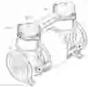
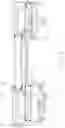
FIG. 1 is a perspective view of the present invention;
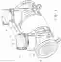
FIG. 2 is an exploded view of the present invention;
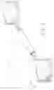
FIG. 3 is an exploded view of a cap member of the present invention;
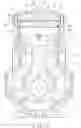
FIG. 4 is a partially sectional view of the present invention;
FIG. 5 is a cross-sectional view showing fasteners inserting through first threaded holes, second threaded holes and third threaded holes to secure the cap member, a fixing plate and a main body of the present invention; and
FIG. 6 is a cross-sectional view of the present invention.
DETAILED DESCRIPTION OF THE PREFERRED EMBODIMENT
Referring to FIG. 1 thru 5, the air compressor structure of the present invention comprises a main body 1, a fixing plate 2, a cap member 3, and fasteners 4.
The main body 1 has a pair of cylinders 11. Each cylinder 11 comprises a plunger 12 therein and a fixture 13 on an outer wall thereof. The fixture 13 has a pair of first threaded holes 14 thereon.
The fixing plate 2 comprises a handle 21 and a pair of fixing portions 22 extending from two sides of the handle 21. The pair of fixing portions 22 corresponds to the pair of cylinders 11. Each fixing portion 22 comprises a fixing section 221 and a recess 222 thereon. The fixing section 221 has a first air sealing ring 23 thereon and is mounted in the cylinder 11 of the main body 1. A second air sealing ring 24 is provided in the recess 222. The fixing portion 22 is formed with an air hole 25 and a stop plate 26 disposed on top of the air hole 25 as a cover to prevent air flow through the air hole 25 into the cylinder 11. The fixing portion 22 further has a slot 27 thereon and a pair of first lugs 28 which has a pair of second threaded holes 281 corresponding in position to the first threaded holes 14 of the fixture 13.
The cap member 3 comprises a tube 31 having an air passage 311 therein, a pair of third air sealing rings 32 at two ends of the tube 31, and a pair of lids 33 attached to the pair of third sealing rings 32 at the two ends of the tube 31. The pair of lids 33 corresponds to the pair of fixing portions 22 of the fixing plate 2. Each lid 33 covers the fixing portion 22 and is against the second air sealing ring 24. Each lid 33 comprises a chamber 331 interconnecting with the air passage 311 of the tube 31, a stud 34 corresponding to the slot 27 of the fixing portion 22, and a pair of second lugs 35 corresponding to the pair of first lugs 28. The second lugs 35 have a pair of third threaded holes 351 corresponding to the first and second threaded holes 14, 281.
The fasteners 4 are inserted through the third threaded holes 351, the second threaded holes 281, and the first threaded holes 14 to secure the cover member 3 and the fixing plate 2 to the main body 1.
When the present invention is in use, as shown in FIG. 6, the plungers 12 are operated in the cylinder 11. Between each cylinder 11 and each fixing portion 22 of the fixing plate 2, the first air sealing ring 23 on the fixing section 221 is used to prevent the air from leakage through each cylinder 11. Between each lid 33 of the cover member 3 and each fixing portion 22 of the fixing plate 2, the second air sealing ring 24 in the recess 222 is used to prevent the air from leakage through the chamber 331. Between the air passage 311 of the cover member 3 and each lid 33, the third air sealing ring 32 is used to prevent the air from leakage through the air passage 311. The operation of the plungers 12 in the cylinders 11 causes a vast vibration which may change the positions of the cylinders 11, the fixing plate 2 and the cap member 3 and result in air leakage. With the engagement of the stud 34 of each lid 33 and the slot 27 of each fixing portion 22, the strength of the cap member 3 and the fixing plate 2 is enhanced. When the plungers 12 are reciprocated in the cylinders 11, the air in the cylinders 11 is compressed and expanded along with the movement of the plungers 12, which generates different vibrations of the two cylinders 11. The handle 21 is adapted to conduct the different vibrations of the cylinders 11 at respective ends so as to stabilize the two cylinders 11. The fasteners 4 are inserted through the third threaded holes 351, the second threaded holes 28 and the first threaded holes 14 to lock the second lugs 35, the first lugs 28, and the fixture 13 together, which increases the stability of the assembly and prevents the cylinders 11 of the main body 1, the fixing plate 2 and the cap member 3 from moving their positions caused by the different vibrations of the cylinders 11.
Claims
What is claimed is:1. An air compressor structure, comprising:
a main body having a pair of cylinders, each of the cylinders comprising a plunger therein and a fixture on an outer wall thereof, the fixture having a pair of first threaded holes thereon;
a fixing plate comprising a handle and a pair of fixing portions extending from two sides of the handle, the pair of fixing portions corresponding to the pair of cylinders, each fixing portion comprising a fixing section and a recess thereon, the fixing section having a first air sealing ring thereon and being mounted in one of the cylinders of the main body, a second air sealing ring being provided in the recess, the fixing portion being formed with an air hole and a stop plate disposed on top of the air hole, the fixing portion further having a slot thereon and a pair of first lugs which has a pair of second threaded holes corresponding in position to the first threaded holes of the fixture;
a cap member comprising a tube having an air passage therein, a pair of third air sealing rings at two ends of the tube, and a pair of lids attached to the pair of third sealing rings at the two ends of the tube, the pair of lids corresponding to the pair of fixing portions of the fixing plate, the lids each covering one of the fixing portions and being against the second air sealing ring, the lids each comprising a chamber interconnecting with the air passage of the tube, a stud corresponding to the slot of the fixing portion, and a pair of second lugs corresponding to the pair of first lugs, the second lugs having a pair of third threaded holes corresponding to the first threaded holes and the second threaded holes; and
fasteners inserting through the third threaded holes, the second threaded holes, and the first threaded holes, respectively, to secure the cover member and the fixing plate to the main body.
Images & Drawings included:


Sources:
- United States Patent and Trademark Office - verify current appl. status at the USPTO↗
Similar patent applications:
- » 20050196290
Protective, convenient-to-use air compressor structure - » 20060022164
Structure air compressor air (water) release valve - » 20120020818
AIR COMPRESSOR STRUCTURE FOR PAINT SPRAYING - » 20250043705
CRANKCASE AIR VALVE STRUCTURE AND AIR COMPRESSOR - » 20080014099
PASSAGE STRUCTURE FOR AIR COMPRESSOR - » 20080187438
AIR FLOW CHANNEL STRUCTURE FOR AIR COMPRESSOR - » 20070264139
Air compressor having stabilized structure - » 20070098583
Air compressor having detachable structure - » 20070065311
Air compressor having changeable structure - » 20080232980
Digit button-operated air compressor output control structure
Recent applications in this class:
- » 20250154942 2025-05-15
ELECTRIC SCROLL COMPRESSOR - » 20250137443 2025-05-01
Pressure Relief System for a Portable Air Pump and Inflator System - » 20250122868 2025-04-17
Refrigerant Compressor - » 20250035099 2025-01-30
APPARATUS AND METHOD OF OPERATING A GAS PUMP - » 20250012264 2025-01-09
Electric Air Pump - » 20240426286 2024-12-26
RECIPROCATING COMPRESSOR USING OUTER ROTOR MOTOR - » 20240410349 2024-12-12
Rotary compressor and air conditioner - » 20240401596 2024-12-05
PORTABLE AIR PUMP - » 20240401579 2024-12-05
Core of dual-motor driven inflatable pump - » 20240392766 2024-11-28
COMPRESSOR