Quick attaching fluid head
US20110073680A1
2011-03-31
12/992,461
2009-05-14
✅ Patent granted
US 9,381,533 B2
2016-07-05
WO; PCT/US2009/043917; 20090514
WO; WO2009/140472; 20091119
Len Tran | Alexander Valvis
Kinney & Lange, P.A.
2030-08-01
Abstract:
The fluid section or head (10) for a plural component applicator can be easily assembled or removed from the air section (12) by turning the fluid head ⅛ of a turn. The fluid head (10) has four tabs (14) that protrude and engage with four undercut features (16) within the handle (12). Tabs (14) are inserted through corresponding openings (16) in the front (12a) of air section (12) and rotated such that tabs (14) are retained behind lips (18). A locking tab feature (20) in the hose manifold (24) mates to a recess feature (22) in the handle (12) to prevent the fluid section (10) from rotating.
Inventors:
- Joseph E. Tix 58 🇺🇸 Hastings, MN, United States
- Christopher J. Pellin 14 🇺🇸 Burnsville, MN, United States
- Mark T. Weinberger 57 🇺🇸 Mounds View, MN, United States
Assignee:
- Graco Minnesota Inc. 479 🇺🇸 Minneapolis, MN, United States
Applicant:
Interested in similar patents?
Get notified when new applications in this technology area are published.
Classification:
B05B15/50 » CPC further
Details of spraying plant or spraying apparatus not otherwise provided for; Accessories Arrangements for cleaning; Arrangements for preventing deposits, drying-out or blockage; Arrangements for detecting improper discharge caused by the presence of foreign matter
B05B7/0815 » CPC further
Spraying apparatus for discharge of liquids or other fluent materials from two or more sources, e.g. of liquid and air, of powder and gas; Spray pistols; Apparatus for discharge with separate outlet orifices, e.g. to form parallel jets , to form intersecting jets to form intersecting jets with at least one gas jet intersecting a jet constituted by a liquid or a mixture containing a liquid for controlling the shape of the latter
B05B7/0408 » CPC further
Spraying apparatus for discharge of liquids or other fluent materials from two or more sources, e.g. of liquid and air, of powder and gas; Spray pistols; Apparatus for discharge with arrangements for mixing liquids or other fluent materials before discharge with arrangements for mixing two or more liquids
B05B7/0416 » CPC further
Spraying apparatus for discharge of liquids or other fluent materials from two or more sources, e.g. of liquid and air, of powder and gas; Spray pistols; Apparatus for discharge with arrangements for mixing liquids or other fluent materials before discharge with arrangements for mixing one gas and one liquid
B05B7/02 » CPC further
Spraying apparatus for discharge of liquids or other fluent materials from two or more sources, e.g. of liquid and air, of powder and gas Spray pistols; Apparatus for discharge
B05B7/12 IPC
Spraying apparatus for discharge of liquids or other fluent materials from two or more sources, e.g. of liquid and air, of powder and gas; Spray pistols; Apparatus for discharge designed to control volume of flow, e.g. with adjustable passages
B05B7/24 IPC
Spraying apparatus for discharge of liquids or other fluent materials from two or more sources, e.g. of liquid and air, of powder and gas with means, e.g. a container, for supplying liquid or other fluent material to a discharge device
F16L35/00 IPC
Special arrangements used in connection with end fittings of hoses, e.g. safety or protecting devices
F16L37/00 IPC
Couplings of the quick-acting type
B05B15/00 » CPC main
Details of spraying plant or spraying apparatus not otherwise provided for; Accessories
B05B7/08 IPC
Spraying apparatus for discharge of liquids or other fluent materials from two or more sources, e.g. of liquid and air, of powder and gas; Spray pistols; Apparatus for discharge with separate outlet orifices, e.g. to form parallel jets , to form intersecting jets
B05B9/01 » CPC further
Spraying apparatus for discharge of liquids or other fluent material, without essentially mixing with gas or vapour Spray pistols, discharge devices
B05B7/04 IPC
Spraying apparatus for discharge of liquids or other fluent materials from two or more sources, e.g. of liquid and air, of powder and gas; Spray pistols; Apparatus for discharge with arrangements for mixing liquids or other fluent materials before discharge
Description
TECHNICAL FIELD
This application claims the benefit of U.S. Application Ser. No. 61/053,430 filed May 15, 2008, the contents of which are hereby incorporated by reference.
BACKGROUND ART
Spray guns for application of fast setting materials such as polyurethanes and polyureas are well known. Because these materials set up so fast, it is important that the gun or applicator be easily disassembled with a minimum of tools for cleaning.
DISCLOSURE OF THE INVENTION
An object of this invention is to develop a simple method of attaching the high-pressure fluid section to lower pressure air section (handle). The fluid section can be easily assembled/removed from the air section by turning the fluid head ⅛ of a turn. The fluid head has four tabs that protrude and engage with four undercut features within the handle. Machined features in the air section (handle) prevent the fluid head from over rotating during assembly/removal by limiting rotation to ⅛ of a turn. When fully assembled, a locking tab feature in the hose manifold mates to a recess feature in the handle to prevent the fluid section from rotating. This construction uses fewer parts and is easy to assemble and remove.
These and other objects and advantages of the invention will appear more fully from the following description made in conjunction with the accompanying drawings wherein like reference characters refer to the same or similar parts throughout the several views.
BRIEF DESCRIPTION OF DRAWINGS
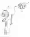
FIG. 1 shows an exploded view of the fluid head relative to the air section.
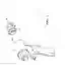
FIG. 2 shows the fluid head during the first stage of assembly to a portion of the air section.
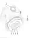
FIG. 3 shows the fluid head during the next stage of assembly to a portion of the air section.
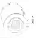
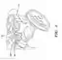
FIG. 4 shows the fluid head assembled to the air section with the hose manifold.
BEST MODE FOR CARRYING OUT THE INVENTION
The fluid section or head 10 of the instant invention can be easily assembled or removed from the air section 12 by turning the fluid head ⅛ of a turn. The fluid head 10 has four tabs 14 that protrude and engage with four undercut features 16 within the handle 12 (see FIG. 1). FIG. 2 shows tabs 14 being inserted through corresponding openings 16 in the front 12a of air section 12 while FIG. 3 shows air section 10 having been rotated such that tabs 14 are retained behind lips 18. Machined features in the air section (handle) 12 prevent the fluid head 10 from over rotating during assembly or removal limiting rotation to ⅛ of a turn.
To finish assembly, a locking tab feature 20 in the hose manifold 24 mates to a recess feature 22 in the handle 12 to prevent the fluid section 10 from rotating (see FIG. 4). The hose manifold 24 is secured to fluid section 12 by means of a bolt or other known fastener 26. Once this is tightened, the manifold 24, fluid section 10 and handle 12 are all fixed relative to each other. Disassembly is, of course, the opposite of assembly. Bolt 26 is removed which allows hose manifold to be removed from the fluid section 10. This in turn allows fluid section 10 to be rotated ⅛ of a turn and separated from the handle.
It is contemplated that various changes and modifications may be made to the quick attaching fluid head without departing from the spirit and scope of the invention as defined by the following claims.
Claims
1. A fluid section assembly for a fast set plural component spray gun having a handle, said assembly comprising
said handle having a recess and a plurality of undercut features;
a head comprising a plurality of tabs that protrude and engage with said handle undercut features so that said tabs when rotated are retained behind said handle undercut features; and
a hose manifold comprising a locking tab which mates to said recess in said handle to prevent said fluid section 10 from rotating
2. The fluid section assembly for a fast set plural component spray gun of claim 1 wherein said hose manifold is secured to said fluid section with a fastener.
Images & Drawings included:
Sources:
- United States Patent and Trademark Office - verify current appl. status at the USPTO↗
Recent applications in this class:
- » 20250091080 2025-03-20
LIQUID JET DEVICE - » 20240316587 2024-09-26
SPRAY OR DISPENSING BOTTLE WITH A BOTTOM STORAGE COMPARTMENT - » 20240261811 2024-08-08
Sprinkler Informational Tag - » 20230022055 2023-01-26
Fluid sprayer with covered battery - » 20220126315 2022-04-28
DEVICES, SYSTEMS, AND METHODS FOR COATING PRODUCTS - » 20220062938 2022-03-03
Low temperature low-abundance atomic object dispenser - » 20210114052 2021-04-22
Spray gun with faux carbon fiber pattern - » 20190143359 2019-05-16
Sound producing member adapted to press at any angle, press-switching water discharging mechanism and shower head - » 20190060941 2019-02-28
Protective device for spraying of aluminum alloy wheel - » 20180126403 2018-05-10
Sound localization perfume nozzle assembly
Recent applications for this Assignee:
- » 20250101975 2025-03-27
PUMP ROD AND DRIVING LINK WITH SIDE-LOAD REDUCING CONFIGURATION - » 20240383119 2024-11-21
POWER TOOL ATTACHMENT - » 20240375133 2024-11-14
FLUID SPRAYER WITH COVERED BATTERY - » 20240316577 2024-09-26
Fluid sprayer - » 20240309595 2024-09-19
ROAD TAPING MACHINE - » 20240293832 2024-09-05
Fluid sprayer - » 20240226943 2024-07-11
Fluid sprayer with battery power - » 20240219937 2024-07-04
PAINT SPRAYER DISTRIBUTED CONTROL AND OUTPUT VOLUME MONITORING ARCHITECTURES - » 20240213720 2024-06-27
Heated hose electrical connectors - » 20240207875 2024-06-27
Mix chamber for a plural component sprayer