HEAT-DISSIPATING STRUCTURE WITH HIGH HEAT-DISSIPATING EFFICIENCY AND METHOD FOR MANUFACTURING THE SAME
US20110083829A1
2011-04-14
12/576,554
2009-10-09
Abstract:
A method for manufacturing a heat-dissipating structure with high heat-dissipating efficiency, includes the following steps: providing a heat-dissipating casing having a hollow heat-dissipating body that has at least two ends; closing one end of the hollow heat-dissipating body; pouring work liquid from other end of the hollow heat-dissipating body into an inner portion of the hollow heat-dissipating body; cooling the work liquid from the liquid state to the solid state by an external cooling medium; extracting air from the hollow heat-dissipating body; and then closing the other end of the hollow heat-dissipating body to form an evacuated hollow heat-dissipating body.
Inventors:
- CHIEN-WEI LEE 2 🇹🇼 Hsinchu City, Taiwan
- Shui-Hsu HUNG 1 🇹🇼 Tainan City, Taiwan
- Shih-Wei LEE 2 🇹🇼 Fongshan City, Taiwan
Interested in similar patents?
Get notified when new applications in this technology area are published.
Classification:
F28D15/0233 » CPC main
Heat-exchange apparatus with the intermediate heat-transfer medium in closed tubes passing into or through the conduit walls ; Heat-exchange apparatus employing intermediate heat-transfer medium or bodies in which the medium condenses and evaporates, e.g. heat pipes the conduits having a particular shape, e.g. non-circular cross-section, annular
F28D15/0283 » CPC further
Heat-exchange apparatus with the intermediate heat-transfer medium in closed tubes passing into or through the conduit walls ; Heat-exchange apparatus employing intermediate heat-transfer medium or bodies in which the medium condenses and evaporates, e.g. heat pipes Means for filling or sealing heat pipes
F28D15/046 » CPC further
Heat-exchange apparatus with the intermediate heat-transfer medium in closed tubes passing into or through the conduit walls ; Heat-exchange apparatus employing intermediate heat-transfer medium or bodies in which the medium condenses and evaporates, e.g. heat pipes with tubes having a capillary structure characterised by the material or the construction of the capillary structure
F28F1/022 » CPC further
Tubular elements; Assemblies of tubular elements; Tubular elements of cross-section which is non-circular with multiple channels
H01L23/427 » CPC further
Details of semiconductor or other solid state devices; Arrangements for cooling, heating, ventilating or temperature compensation ; Temperature sensing arrangements; Fillings or auxiliary members in containers or encapsulations selected or arranged to facilitate heating or cooling Cooling by change of state, e.g. use of heat pipes
B23P2700/09 » CPC further
Indexing scheme relating to the articles being treated, e.g. manufactured, repaired, assembled, connected or other operations covered in the subgroups Heat pipes
Y10T29/49353 » CPC further
Metal working; Method of mechanical manufacture; Heat exchanger or boiler making Heat pipe device making
H01L2924/0002 » CPC further
Indexing scheme for arrangements or methods for connecting or disconnecting semiconductor or solid-state bodies as covered by; Technical content checked by a classifier Not covered by any one of groups , and
H01L2924/00 » CPC further
Indexing scheme for arrangements or methods for connecting or disconnecting semiconductor or solid-state bodies as covered by
F28D15/04 IPC
Heat-exchange apparatus with the intermediate heat-transfer medium in closed tubes passing into or through the conduit walls ; Heat-exchange apparatus employing intermediate heat-transfer medium or bodies in which the medium condenses and evaporates, e.g. heat pipes with tubes having a capillary structure
B21D53/02 IPC
Making other particular articles heat exchangers , e.g. radiators, condensers
Description
BACKGROUND OF THE INVENTION
1. Field of the Invention
The present invention relates to a heat-dissipating structure and a method for manufacturing the same, in particular, to a heat-dissipating structure with high heat-dissipating efficiency and a method for manufacturing the same.
2. Description of Related Art
Cooling or heat removal has been one of the major obstacles of the electronic industry. The heat dissipation increases with the scale of integration, the demand for higher performance, and the increase of multi-functional applications. The development of high performance heat transfer devices becomes one of the major development efforts of the industry. Heat pipes have excellent heat transfer performance due to their low thermal resistance, and are therefore an effective means for transfer or dissipation of heat from heat sources. Currently, heat pipes are widely used for removing heat from heat-generating components such as central processing units (CPUs) of computers.
A heat pipe is usually a vacuum casing containing therein a working medium, which is employed to carry, under phase transitions between liquid state and vapor state, thermal energy from an evaporator section to a condenser section of the heat pipe. Preferably, a wick structure is provided inside the heat pipe, lining an inner wall of the casing, for drawing the working medium back to the evaporator section after it is condensed at the condenser section. In operation, the evaporator section of the heat pipe is maintained in thermal contact with a heat-generating component. The working medium contained at the evaporator section absorbs heat generated by the heat-generating component and then turns into vapor and moves towards the condenser section where the vapor is condensed into condensate after releasing the heat into ambient environment. Due to the difference in capillary pressure which develops in the wick structure between the two sections, the condensate is then brought back by the wick structure to the evaporator section where it is again available for evaporation.
However, one part of work liquid that has been poured into the heat pipe would be extracted out during vacuum pumping process, so that the liquid measure of the work liquid is less than original work liquid that has been poured into the heat pipe. In order to keep a predetermined liquid measure of the work liquid in the heat pipe, the vacuum level of the heat pipe needs to be decreased. Hence, the heat-dissipating efficiency of the heat pipe of the prior art is decreased.
SUMMARY OF THE INVENTION
In view of the aforementioned issues, the present invention provides a heat-dissipating structure with high heat-dissipating efficiency and a method for manufacturing the same. The present invention can keep a predetermined liquid measure of work liquid and achieve a better vacuum level, so that the present invention can obtain high heat-dissipating efficiency.
To achieve the above-mentioned objectives, the present invention provides a heat-dissipating structure with high heat-dissipating efficiency, including: a heat-dissipating casing and a plurality of solid work liquids. The heat-dissipating casing has an evacuated hollow heat-dissipating body and a plurality of microstructures integratedly formed on an inner surface of the hollow heat-dissipating body. The hollow heat-dissipating body has at least two ends that have been closed. The solid work liquids are received in the hollow heat-dissipating body.
To achieve the above-mentioned objectives, the present invention provides a method for manufacturing a heat-dissipating structure with high heat-dissipating efficiency. The method includes providing a heat-dissipating casing having a hollow heat-dissipating body that has at least two ends; closing one end of the hollow heat-dissipating body; pouring work liquid from other end of the hollow heat-dissipating body into an inner portion of the hollow heat-dissipating body; cooling the work liquid from the liquid state to the solid state by an external cooling medium; extracting air from the hollow heat-dissipating body; and then closing the other end of the hollow heat-dissipating body to form an evacuated hollow heat-dissipating body.
Therefore, work liquid is pre-solidifying to become solid state, so that the present invention can control the liquid measure of the work liquid and can increase air-extracting time in order to increase the vacuum level of the hollow heat-dissipating body. Hence, the present invention has good heat-dissipating efficiency.
In order to further understand the techniques, means and effects the present invention takes for achieving the prescribed objectives, the following detailed descriptions and appended drawings are hereby referred, such that, through which, the purposes, features and aspects of the present invention can be thoroughly and concretely appreciated; however, the appended drawings are merely provided for reference and illustration, without any intention to be used for limiting the present invention.
BRIEF DESCRIPTION OF THE DRAWINGS
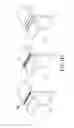
FIG. 1 is a flowchart of the method for manufacturing a heat-dissipating structure with high heat-dissipating efficiency according to the first embodiment of the present invention;
FIGS. 1A1 to 1F are schematic views of the heat-dissipating structure with high heat-dissipating efficiency according to the first embodiment of the present invention, at different stages of the manufacturing processes, respectively; and
FIG. 2 is a partial, cross-sectional, schematic view of the heat-dissipating structure with high heat-dissipating efficiency according to the second embodiment of the present invention.
DETAILED DESCRIPTION OF THE PREFERRED EMBODIMENTS
Referring to FIGS. 1 and 1A1-1E, the first embodiment of the present invention provides a method for manufacturing a heat-dissipating structure with high heat-dissipating efficiency. The method includes the following steps:
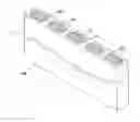
The step S100 is that: referring to FIGS. 1, 1A1 and 1A2, providing a heat-dissipating casing 1 having a hollow heat-dissipating body 10 that has at least two ends (10A, 10B). In addition, the heat-dissipating casing 1 has a plurality of microstructures 11 integratedly formed on an inner surface of the hollow heat-dissipating body 10 and a plurality of supports 12 integratedly formed in the hollow heat-dissipating body 10 in order to divide an inner space of the hollow heat-dissipating body 10 into a plurality of receiving spaces 100.
Moreover, the heat-dissipating casing 1 can be made of metal material or any other material. For example, the metal material can be selected from the group consisting of aluminum, copper, iron, steel, stainless steel, nickel and titanium. In addition, the hollow heat-dissipating body 10 is a hollow pipe formed by extrusion molding or deep drawing, and hollow pipe has a plane shape, a fin shape or a groove shape. Furthermore, the microstructures 11 are composed of a plurality of capillary structures, and the cross-sectional shape of each microstructure 11 can be triangle, square, rectangle, trapezoid or arc. However, the inner structure of the hollow heat-dissipating body 10, the material property of the heat-dissipating casing 1, the forming method of the hollow heat-dissipating body 10, the shape of the hollow heat-dissipating body 10 and the cross-sectional shape of each microstructure 11 are just examples. These do not limit the present invention.
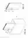
The step S102 is that: referring to FIGS. 1, 1B1 and 1B2, closing one end 10B of the hollow heat-dissipating body 10. For example, one end 10B of the hollow heat-dissipating body 10 is closed by a press-fitting clamp C with normal or high temperature (such as 200° C.), and the width W1 of the clamp C is equal to or larger than the width W2 of the hollow heat-dissipating body 10.
The step S104 is that: referring to FIGS. 1 and 1C, pouring work liquid W from other end 10A of the hollow heat-dissipating body 10 into an inner portion of the hollow heat-dissipating body 10. The work liquid W is filled into the receiving spaces 100. In addition, the work liquid W can be selected from the group consisting of pure water, ammonia, methanol, ethanol, propane and heptane, and the receiving spaces 100 receive the work liquid W with the same property or different property. In other words, the work liquid W with the same property can be filled into the receiving spaces 100 or the work liquid W with different property can be alternatively filled into the receiving spaces 100 according to different requirement. For example, referring to FIG. 1C, alcohol can be filled into the first, the third and the fifth receiving spaces 100 and propane is filled into the second and the fourth receiving spaces 100 in order to achieve composite heat-dissipating efficiency.
The step S106 is that: referring to FIGS. 1 and 1D, cooling the work liquid W from the liquid state to the solid state by an external cooling medium M. In other words, one side of the hollow heat-dissipating body 10 is disposed into the external cooling medium M for cooling the work liquid W, so that the liquid work liquid W is frozen to form the solid work liquid W′. In addition, the external cooling medium M can be a freezer, a cryogenic cooler, refrigerant, liquid air, liquid nitrogen, liquid helium or any other cooling medium. The relationship between minimum work temperature, freezing temperature and applied field are shown as the following tables:
| External cooling medium | Minimum work temperature | |
| freezer | −25° C. | |
| refrigerant | −110° C. | |
| cryogenic cooler | −140° C. | |
| liquid air | −192° C. | |
| liquid nitrogen | −196° C. | |
| liquid helium | −269° C. | |
| Work liquid | pure water | ammonia | methanol | ethanol | propane |
| freezing | 0.1 | −77.5 | −97.9 | −114.3 | −93 |
| temperature (° C.) | |||||
| Work liquid | pentane | heptane | toluene | mercury | |
| freezing | −129.9 | −90.5 | −94.9 | −38.8 | |
| temperature (° C.) | |||||
| Work liquid | pure water | ammonia | methanol | ethanol | propane |
| Cooling medium | 0.1 | −77.5 | −97.9 | −114.3 | −93 |
| freezer | ∘ | ||||
| refrigerant | ∘ | ∘ | ∘ | ∘ | |
| cryogenic cooler | ∘ | ∘ | ∘ | ∘ | ∘ |
| liquid air | ∘ | ∘ | ∘ | ∘ | ∘ |
| liquid nitrogen | ∘ | ∘ | ∘ | ∘ | ∘ |
| liquid helium | ∘ | ∘ | ∘ | ∘ | ∘ |
| Work liquid | pentane | heptane | toluene | mercury | |
| Cooling medium | −129.9 | −90.5 | −94.9 | −38.8 | |
| freezer | |||||
| refrigerant | ∘ | ∘ | ∘ | ||
| cryogenic cooler | ∘ | ∘ | ∘ | ∘ | |
| liquid air | ∘ | ∘ | ∘ | ∘ | |
| liquid nitrogen | ∘ | ∘ | ∘ | ∘ | |
| liquid helium | ∘ | ∘ | ∘ | ∘ | |
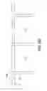
The step S108 is that: referring to FIG. 1, extracting air from the hollow heat-dissipating body 10. Because the solid work liquid W′ is in solid state, so the solid work liquid W′ does not be extracted out during the step of extracting air from the hollow heat-dissipating body 10. Hence, the present invention can keep a predetermined liquid measure and achieve a better vacuum level. In other words, the solid work liquid W′ is in solid state, so that the present invention can control the liquid measure of the work liquid W (The maximum liquid measure of the work liquid W is 99%) and can increase air-extracting time in order to increase the vacuum level of the hollow heat-dissipating body 10.
The step S110 is that: referring to FIGS. 1, 1E1 and 1E2, closing the other end 10A of the hollow heat-dissipating body 10 to form an evacuated hollow heat-dissipating body. For example, the other end 10A of the hollow heat-dissipating body 10 is closed by a press-fitting clamp C with normal or high temperature (such as 200° C.), and the width W1 of the clamp C is equal to or larger than the width W2 of the hollow heat-dissipating body 10.
Therefore, the first embodiment of the present invention provides a heat-dissipating structure (half-finished product) with high heat-dissipating efficiency. The heat-dissipating structure includes a heat-dissipating casing 1 and a plurality of solid work liquids W′. The heat-dissipating casing 1 can be a heat pipe, and the heat pipe has at least two ends that have been closed. In addition, the heat-dissipating casing 1 has an evacuated hollow heat-dissipating body 10, a plurality of microstructures 11 integratedly formed on an inner surface of the hollow heat-dissipating body 10, and a plurality of supports 12 integratedly formed in the hollow heat-dissipating body 10 in order to divide an inner space of the hollow heat-dissipating body 10 into a plurality of receiving spaces 100. The solid work liquids W′ are received in the hollow heat-dissipating body 10, and the solid work liquids W′ are filled into the receiving spaces 100.
After the other end 10A of the hollow heat-dissipating body 10 is closed and the solid work liquids W′ is heated to become liquid state, the heat-dissipating structure of the present invention is finished. The work temperature range of the present invention is shown as the following table:
| Work temperature range | |
| (° C.) | Major work liquid |
| −273~−70 | Helium, neon, argon, krypton, hydrogen, |
| (cryogenic temperature) | nitrogen, oxygen, methane |
| −70~200 | Freon, ethane, ammonia, pentane, heptane, |
| (low temperature) | acetone, methanol, ethanol, water, toluene |
| 200~500 | Naphthalene, dowtherm, thermex, sulfur, |
| (medial temperature) | mercury |
| 500~1000 | Cesium, rubidium, potassium, sodium |
| (high temperature) | |
| over 1000 | Lithium, calcium, lead, indium, silver |
| (high temperature) | |
Moreover, referring to FIG. 1F, the air-tight seal level of the two ends (10A′, 10B′) of the hollow heat-dissipating body 10′ is increased by using physical or chemical process to form an outer coating E on the two ends (10A′, 10B′) of the hollow heat-dissipating body 10′. In addition, the physical process includes plastic deformation, welding, laser, ultrasound wave, impregnation method or physical vapor deposition, and the chemical process includes electroplating, electroforming or chemical vapor deposition. The composition of coatings can be pure metal, alloy, oxide, polymer or epoxy.
Referring to FIG. 2, the hollow heat-dissipating body 10″ has an inner coating L formed on an inner surface thereof (the inner surface of the receiving spaces 100″) in order to increase the air-tight seal level of the two ends of the hollow heat-dissipating body 10″ by electroplating, anode process, sol gel or chemical conversion coating. The inner coating L can be made of copper, aluminum, tin, lead, zinc, magnesium, silicon or hot melt glue. When the two ends of the hollow heat-dissipating body 10″ are closed, the air-tight seal level of the two ends of the hollow heat-dissipating body 10″ is increased by using the inner coating L.
In conclusion, the work liquid is pre-solidifying to become solid state, so that the present invention can control the liquid measure of the work liquid and can increase air-extracting time in order to increase the vacuum level of the hollow heat-dissipating body. Hence, the present invention has good heat-dissipating efficiency.
The above-mentioned descriptions represent merely the preferred embodiment of the present invention, without any intention to limit the scope of the present invention thereto. Various equivalent changes, alternations or modifications based on the claims of present invention are all consequently viewed as being embraced by the scope of the present invention.
Claims
What is claimed is:1. A heat-dissipating structure with high heat-dissipating efficiency, comprising:
a heat-dissipating casing having an evacuated hollow heat-dissipating body and a plurality of microstructures integratedly formed on an inner surface of the hollow heat-dissipating body, wherein the hollow heat-dissipating body has at least two ends that have been closed; and
a plurality of solid work liquids received in the hollow heat-dissipating body.
2. The heat-dissipating structure according to claim 1, wherein the heat-dissipating casing includes a plurality of supports integratedly formed in the hollow heat-dissipating body in order to divide an inner space of the hollow heat-dissipating body into a plurality of receiving spaces, and the solid work liquids are filled into the receiving spaces.
3. The heat-dissipating structure according to claim 2, wherein the solid work liquids are selected from the group consisting of pure water, ammonia, methanol, ethanol, propane and heptane, and the receiving spaces receive the solid work liquids with the same property or different property.
4. The heat-dissipating structure according to claim 1, wherein the heat-dissipating casing is a heat pipe, and the heat pipe has at least two ends that have been closed.
5. The heat-dissipating structure according to claim 1, wherein the microstructures are composed of a plurality of capillary structures.
6. The heat-dissipating structure according to claim 1, wherein the heat-dissipating casing is made of metal material, and the metal material is selected from the group consisting of aluminum, copper, iron, steel, stainless steel, nickel and titanium.
7. The heat-dissipating structure according to claim 1, wherein the cross-sectional shape of each microstructure is triangle, square, rectangle, trapezoid or arc.
8. A method for manufacturing a heat-dissipating structure with high heat-dissipating efficiency, comprising:
providing a heat-dissipating casing having a hollow heat-dissipating body that has at least two ends;
closing one end of the hollow heat-dissipating body;
pouring work liquid from other end of the hollow heat-dissipating body into an inner portion of the hollow heat-dissipating body;
cooling the work liquid from the liquid state to the solid state by an external cooling medium;
extracting air from the hollow heat-dissipating body; and
closing the other end of the hollow heat-dissipating body to form an evacuated hollow heat-dissipating body.
9. The method according to claim 8, wherein the heat-dissipating casing has a plurality of microstructures integratedly formed on an inner surface of the hollow heat-dissipating body.
10. The method according to claim 9, wherein the microstructures are composed of a plurality of capillary structures.
11. The method according to claim 9, wherein the cross-sectional shape of each microstructure is triangle, square, rectangle, trapezoid or arc.
12. The method according to claim 8, wherein the heat-dissipating casing includes a plurality of supports integratedly formed in the hollow heat-dissipating body in order to divide an inner space of the hollow heat-dissipating body into a plurality of receiving spaces, and the work liquid is filled into the receiving spaces.
13. The method according to claim 12, wherein the work liquid is selected from the group consisting of pure water, ammonia, methanol, ethanol, propane and heptane, and the receiving spaces receive the work liquid with the same property or different property, so that the same work liquid or different work liquid is filled in the receiving spaces.
14. The method according to claim 8, wherein the heat-dissipating casing is made of metal material, and the metal material is selected from the group consisting of aluminum, copper, iron, steel, stainless steel, nickel and titanium.
15. The method according to claim 8, wherein the hollow heat-dissipating body is a hollow pipe formed by extrusion molding or deep drawing, and hollow pipe has a plane shape, a fin shape or a groove shape.
16. The method according to claim 8, wherein the external cooling medium is a freezer, a cryogenic cooler, refrigerant, liquid air, liquid nitrogen or liquid helium, and the cooling temperature of the external cooling medium is ranged from −273° C. to 15° C.
17. The method according to claim 8, wherein the two ends of the hollow heat-dissipating body are closed by a press-fitting clamp with normal or high temperature, and the width of the clamp is equal to or larger than that of the hollow heat-dissipating body.
18. The method according to claim 8, wherein the hollow heat-dissipating body has an inner coating formed on an inner surface thereof in order to increase air-tight seal level of the two ends of the hollow heat-dissipating body by electroplating, anode process, sol gel or chemical conversion coating, and the inner coating is made of copper, aluminum, tin, lead, zinc, magnesium, silicon or hot melt glue.
19. The method according to claim 8, wherein air-tight seal level of the two ends of the hollow heat-dissipating body is increased by using physical or chemical process.
20. The method according to claim 19, wherein the physical process includes plastic deformation, welding, laser, ultrasound wave or physical vapor deposition, and the chemical process includes electroplating, electroforming or chemical vapor deposition.
Images & Drawings included:


Sources:
- United States Patent and Trademark Office - verify current appl. status at the USPTO↗
Recent applications in this class:
- » 20250067519 2025-02-27
THREE-DIMENSIONAL HEAT TRANSFER DEVICE - » 20250052511 2025-02-13
VAPOR CHAMBER HEATSINK ASSEMBLY - » 20250012514 2025-01-09
HEATPIPE WITH GRADUATED CONDENSER PORTION AND CONSTANT RATIO BETWEEN WICK THICKNESS AND CROSS-SECTION AREA - » 20240426558 2024-12-26
DYNAMICALLY ENHANCING HEAT TRANSFER THROUGH HEAT PIPES - » 20240410656 2024-12-12
COMPOSITE HEAT EXCHANGE APPARATUS FOR A TURBINE ENGINE - » 20240361082 2024-10-31
VAPOR CHAMBER - » 20240344773 2024-10-17
VAPOR CHAMBER DEVICE - » 20240247877 2024-07-25
EMBEDDED-LATTICE-JIG, ISOTHERMAL, TRUSS-PLATE APPARATUS AND METHOD - » 20240175638 2024-05-30
3D VAPOR CHAMBER - » 20240125559 2024-04-18
BODY SHEET FOR VAPOR CHAMBER, VAPOR CHAMBER, AND ELECTRONIC APPARATUS