Network cabinet fitting system
US20110083873A1
2011-04-14
12/902,861
2010-10-12
✅ Patent granted
US 8,791,367 B2
2014-07-29
-
-
Boris Chervinsky | Pete Lee
Christopher S. Clancy | James H. Williams
2032-01-04
Abstract:
A fitting system for sealing an opening in a top cap of a network cabinet includes a grommet and at least one of a fitting assembly and a cover. The grommet is secured to the opening in the top cap of the network cabinet. The fitting assembly and the cover are secured to the grommet and may include at least one finger lift. A sleeve or a tube may be secured to the fitting assembly.
Inventors:
- Scott R. Hartman 34 🇺🇸 Oak Forest, IL, United States
- Scott M. Lesniak 18 🇺🇸 Lockport, IL, United States
- Dale A. Block 5 🇺🇸 Schererville, IN, United States
- Edward G. Blomquist 3 🇺🇸 Plainfield, IL, United States
Assignee:
- PANDUIT CORP. 1,097 🇺🇸 Tinley Park, IL, United States
Applicant:
Interested in similar patents?
Get notified when new applications in this technology area are published.
Classification:
H05K5/03 IPC
Casings, cabinets or drawers for electric apparatus; Details Covers
H05K5/03 IPC
Casings, cabinets or drawers for electric apparatus; Details Covers
H05K7/1491 » CPC further
Constructional details common to different types of electric apparatus; Mounting supporting structure in casing or on frame or rack; Servers; Data center rooms, e.g. 19-inch computer racks; Cabinets therefor, e.g. chassis or racks or mechanical interfaces between blades and support structures having cable management arrangements
H01B17/26 IPC
Insulators or insulating bodies characterised by their form Lead-in insulators; Lead-through insulators
H05K7/14 IPC
Constructional details common to different types of electric apparatus Mounting supporting structure in casing or on frame or rack
H05K7/14 IPC
Constructional details common to different types of electric apparatus Mounting supporting structure in casing or on frame or rack
H02G3/22 » CPC main
Installations of electric cables or lines in or on buildings, equivalent structures or vehicles Arrangements for leading cables or lines through walls, floors, or ceilings, e.g. into building
H04Q1/10 » CPC further
Details of selecting apparatus or arrangements; Constructional details Exchange station construction
H04Q1/06 » CPC further
Details of selecting apparatus or arrangements; Constructional details Cable ducts or mountings specially adapted for exchange installations
Description
CROSS-REFERENCE TO RELATED APPLICATIONS
This application claims the benefit of U.S. Provisional Patent Application No. 61/251,429, filed on Oct. 14, 2009, the subject matter of which is incorporated by reference in its entirety.
BACKGROUND OF THE INVENTION
The present invention relates to a network cabinet fitting system. More particularly, the present invention relates to a fitting system for openings in a top cap of a network cabinet.
Typically, network cabinets have knockouts or removable openings of various sizes to allow cables to enter and exit the cabinet. When cables are run in or out of the cabinet, air within the cabinet may escape through the openings and around the cables and adversely affect the cabinet cooling systems.
Therefore, there is a need for a network cabinet fitting system that seals around cables to reduce air leaks.
SUMMARY OF THE INVENTION
A fitting system for sealing an opening in a top cap of a network cabinet. The fitting system includes a grommet and at least one of a fitting assembly and a cover. The grommet is secured to the opening in the top cap of the network cabinet. The fitting assembly and the cover are secured to the grommet and may include at least one finger lift. A sleeve or a tube may be secured to the fitting assembly.
BRIEF DESCRIPTION OF THE DRAWINGS
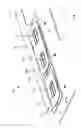
FIG. 1 is a top perspective view of a network cabinet fitting system according to a first preferred embodiment of the present invention;
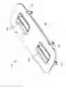
FIG. 2 is a top perspective view of the fitting system of FIG. 1, showing the covers removed from the grommets;
FIG. 3 is a bottom perspective view of a small grommet for the fitting system of FIG. 1;
FIG. 4 is a bottom perspective view of a large grommet for the fitting system of FIG. 1;
FIG. 5 is a top perspective view of a small cover for the fitting system of FIG. 1;
FIG. 6 is an enlarged view of the small cover of FIG. 5, showing a latch;
FIG. 7 is a top perspective view of a large cover for the fitting system of FIG. 1;
FIG. 8 is a top perspective view of a network cabinet fitting system according to a second preferred embodiment of the present invention;
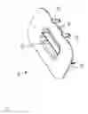
FIG. 9 is a cross-sectional view of a boot fitting assembly for the fitting system of FIG. 8;
FIG. 10 is a top perspective view of a first fitting for the boot fitting assembly of FIG. 9;
FIG. 11 is a top perspective view of a second fitting for the boot fitting assembly of FIG. 9;
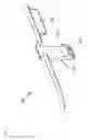
FIG. 12 is a top perspective view of a network cabinet fitting system according to a third preferred embodiment of the present invention;
FIG. 13 is a top perspective view of a first fitting for the corrugated tube fitting assembly of FIG. 12;
FIG. 14 is a bottom perspective view of a partial cover for the corrugated tube fitting assembly of FIG. 12;
FIG. 15 is a top perspective view of the fitting system of FIG. 12, showing the first fitting secured to the large grommet;
FIG. 16 is a top perspective view of the fitting system of FIG. 12, showing the corrugated tube positioned in the first fitting;
FIG. 17 is a top perspective view of the fitting system of FIG. 12, showing the second fitting secured to the large grommet; and
FIG. 18 is a top perspective view of the fitting system of FIG. 12, showing the partial cover secured to the large grommet.
DETAILED DESCRIPTION OF THE PREFERRED EMBODIMENTS
FIGS. 1-7 illustrate a network cabinet fitting system 100 according to a first preferred embodiment of the present invention.
As best seen in FIG. 1, the fitting system 100 includes a small grommet 110, a small cover 120, a large grommet 130, and a large cover 140.
As best seen in FIG. 2, the small grommet 110 is secured to a small opening 11, such as a 3.5 inch by 5.0 inch opening, in a top cap 10 of a network cabinet (not shown), such as the NET-ACCESS™ network cabinet (Panduit Corp., Tinley Park, Ill.) disclosed in U.S. Pat. No. 7,498,512, the subject matter of which is incorporated by reference in its entirety, and includes radius edges 114 for protecting cables routed therethrough. Similarly, the large grommet 130 is secured to a large opening 12, such as a 3.5 inch by 8.0 inch opening, in the top cap 10 and includes radius edges 134 for protecting cables routed therethrough.
As best seen in FIG. 3, the small grommet 110 includes guides 111, for inserting the small grommet 110 into the small opening 11 and latches 112 for securing the small grommet 110 to the small opening 11. Additionally, the small grommet 110 includes stops 113 for locating the corrugated tube fitting assembly 350 (FIGS. 12-18).
As best seen in FIG. 4, the large grommet 130 includes guides 131, latches 132, and stops 133, which are similar to the guides 111, latches 112, and stops 113 of the small grommet 110 (FIG. 3).
As best seen in FIG. 5, the small cover 120 includes guides 121 for inserting the small cover 120 into the small grommet 110 and latches 122 for securing the small cover 120 to the small grommet 110. Additionally, the small cover 120 includes a finger lift 123 for removing the small cover 120 from the small grommet 110.
As best seen in FIG. 6, the latches 122 include a lead-in angle 124 for inserting the small cover 120 into the small grommet 110 and a ramp angle 125 for removing the small cover 120 from the small grommet 110 without having to manually deflect the latches 122.
As best seen in FIG. 7, the large cover 140 includes guides 141, latches 142, and finger lifts 143, which are similar to the guides 121, the latches 122, and the finger lift 123 of the small cover 120 (FIGS. 5-6).
FIGS. 8-11 illustrate a network cabinet fitting system 200 according to a second preferred embodiment of the present invention. As best seen in FIG. 8, the fitting system 200 includes the small grommet 110, the small cover 120, and the large grommet 130. Additionally, the fitting system 200 includes a boot fitting assembly 240. The boot fitting assembly 240 is secured to the large grommet 130.
As best seen in FIG. 9, the boot fitting assembly 240 includes a first fitting 241 and a second fitting 242. Together, the fittings 241, 242 form a channel 243 for receiving a sleeve (not shown), such as the COOL BOOT™ sleeve (Panduit Corp., Tinley Park, Ill.) disclosed in U.S. Pat. No. 7,723,622, the subject matter of which is incorporated by reference in its entirety.
As best seen in FIG. 10, the first fitting 241 includes latches 244 for securing the first fitting 241 to the large grommet 130 and latches 245 (FIG. 9) for securing the second fitting 242 to the first fitting 241. Additionally, the first fitting 241 includes a split 246 for installing the first fitting 241 around existing cables.
As best seen in FIG. 11, the second fitting 242 includes openings 247 for securing the second fitting 242 to the first fitting 241. For example, as shown in FIG. 9, the latches 245 of the first fitting 241 are received within the openings 247 of the second fitting 242. Additionally, the second fitting 242 includes a split 248 for installing the second fitting 242 around existing cables.
FIGS. 12-18 illustrate a network cabinet fitting system 300 according to a third preferred embodiment of the present invention. As best seen in FIG. 12, the fitting system 300 includes the small grommet 110, the small cover 120, the large grommet 130, and the boot fitting assembly 240. Additionally, the fitting system 300 includes a corrugated tube fitting assembly 350. The corrugated tube fitting assembly 350 is secured to the large grommet 130 and includes a first fitting 351, a second fitting 352, and a partial cover 353. Together, the fittings 351, 352 form an opening 354 for receiving a corrugated tube 13 (FIGS. 16-18), for example, from a cable routing system, such as the FIBERRUNNER® cable routing system (Panduit Corp., Tinley Park, Ill.).
As best seen in FIG. 13, the first fitting 351 includes guides 355, latches 356, and a finger lift 357, which are similar to the guides 121, the latches 122, and the finger lift 123 of the small cover 120 (FIGS. 5-6). Preferably, the first fitting 351 and the second fitting 352 are identical.
As best seen in FIG. 14, the partial cover 353 includes guides 358, latches 359, and a finger lift 360 (FIG. 12), which are similar to the guides 121, the latches 122, and the finger lift 123 of the small cover 120 (FIGS. 5-6). Additionally, the partial cover 353 includes a lip 361 that overlaps the second fitting 352 and seals the gap between the partial cover 353 and the second fitting 352.
FIGS. 15-18 illustrate the installation of the corrugated tube fitting assembly 350. As best seen in FIG. 15, the first fitting 351 is secured to the large grommet 130. As best seen in FIG. 16, the corrugated tube 13 is positioned in the first fitting 351. Preferably, the corrugated tube 13 includes a slit (not shown) for installing the corrugated tube 13 around existing cables. As best seen in FIG. 17, the second fitting 352 is secured to the large grommet 130, securing the corrugated tube 13 in the opening 354 (FIG. 12). As best seen in FIG. 18, the partial cover 353 is secured to the large grommet 130, sealing the remaining open space 14 (FIG. 17) in the large grommet 130. Alternatively, the corrugated tube fitting assembly 350 may be secured to the small grommet 110, eliminating the need for the partial cover 353.
Preferably, the components of the fitting systems 100-300, such as the small grommet 110, the small cover 120, the large grommet 130, the boot fitting assembly 240, and the corrugated tube fitting assembly 350, may be combined to form additional embodiments of the present invention.
Preferably, all of the openings 11, 12 in the top cap 10 include a grommet 110, 130 and at least one of a cover 120, 140, a boot fitting assembly 240, and a corrugated tube fitting assembly 350.
While the particular preferred embodiments of the present invention have been shown and described, it will be obvious to those skilled in the art that changes and modifications may be made without departing from the teaching of the invention. The matter set forth in the foregoing description and accompanying drawings is offered by way of illustration only and not as limitation. The illustrated embodiments are examples only and should not be taken as limiting the scope of the present invention. The claims should not be read as limited to the described order or elements unless stated to that effect. Therefore, all embodiments that come within the scope and spirit of the following claims and equivalents thereto are claimed as the invention.
Claims
1. A fitting system for sealing an opening in a top cap of a network cabinet, the fitting system comprising:
a grommet secured to the opening in the top cap of the network cabinet; and
a cover secured to the grommet, the cover including at least one finger lift for removing the cover from the grommet.
2. The fitting system of claim 1, wherein the at least one finger lift is recessed.
3. The fitting system of claim 1, wherein the grommet includes at least one guide for positioning the grommet in the opening of the top cap of the network cabinet.
4. The fitting system of claim 1, wherein the grommet includes at least one latch for securing the grommet to the opening in the top cap of the network cabinet.
5. The fitting system of claim 1, wherein the cover includes at least one guide for positioning the cover in the grommet.
6. The fitting system of claim 1, wherein the cover includes at least one latch for engaging the grommet.
7. A fitting system for sealing an opening in a top cap of a network cabinet, the fitting system comprising:
a grommet secured to the opening in the top cap of the network cabinet;
a fitting assembly secured to the grommet; and
a sleeve secured to the fitting assembly.
8. The fitting system of claim 7, wherein the grommet includes at least one guide for positioning the grommet in the opening of the top cap of the network cabinet.
9. The fitting system of claim 7, wherein the grommet includes at least one latch for securing the grommet to the opening in the top cap of the network cabinet.
10. The fitting system of claim 7, wherein the fitting assembly includes a first fitting secured to the grommet and a second fitting secured to the first fitting.
11. The fitting system of claim 10, wherein the first fitting and the second fitting form a channel for securing the sleeve to the fitting assembly.
12. The fitting system of claim 10, wherein the first fitting includes a split for positioning the first fitting around existing cables routed through the opening in the top cap of the network cabinet.
13. The fitting system of claim 10, wherein the second fitting includes a split for positioning the second fitting around existing cables routed through the opening in the top cap of the network cabinet.
14. The fitting system of claim 10, wherein the first fitting includes at least one latch for securing the first fitting to the grommet.
15. The fitting system of claim 10, wherein the first fitting includes at least one latch for securing the second fitting to the first fitting.
16. The fitting system of claim 15, wherein the second fitting includes at least one opening for securing the second fitting to the first fitting, the at least one opening of the second fitting for receiving the at least one latch of the first fitting.
17. A fitting system for sealing an opening in a top cap of a network cabinet, the fitting system comprising:
a grommet secured to the opening in the top cap of the network cabinet;
a fitting assembly secured to the grommet, the fitting assembly including at least one finger lift for removing the fitting assembly from the grommet; and
a tube secured to the fitting assembly.
18. The fitting system of claim 17, wherein the grommet includes at least one guide for positioning the grommet in the opening of the top cap of the network cabinet.
19. The fitting system of claim 17, wherein the grommet includes at least one latch for securing the grommet to the opening in the top cap of the network cabinet.
20. The fitting system of claim 17, wherein the grommet includes at least one stop for positioning the fitting assembly in the grommet.
21. The fitting system of claim 17, wherein the fitting assembly includes a first fitting secured to the grommet and a second fitting secured to the grommet.
22. The fitting system of claim 21, wherein the first fitting and the second fitting are identical.
23. The fitting system of claim 21, wherein the first fitting and the second fitting form an opening for securing the tube.
24. The fitting system of claim 21, wherein the first fitting includes at least one guide for positioning the first fitting in the grommet.
25. The fitting system of claim 21, wherein the first fitting includes at least one latch for securing the first fitting to the grommet.
26. The fitting system of claim 21, wherein the first fitting includes at least one finger lift for removing the first fitting from the grommet.
27. The fitting system of claim 21, wherein the second fitting includes at least one guide for positioning the second fitting in the grommet.
28. The fitting system of claim 21, wherein the second fitting includes at least one latch for securing the second fitting to the grommet.
29. The fitting system of claim 21, wherein the second fitting includes at least one finger lift for removing the second fitting from the grommet.
30. The fitting system of claim 17, further comprising a partial cover secured to the grommet adjacent the fitting assembly.
31. The fitting system of claim 30, wherein the partial cover includes a lip that overlaps a portion of the fitting assembly.
32. The fitting system of claim 30, wherein the partial cover includes at least one guide for positioning the partial cover in the grommet.
33. The fitting system of claim 30, wherein the partial cover includes at least one latch for securing the partial cover to the grommet.
34. The fitting system of claim 30, wherein the partial cover includes at least one finger lift for removing the partial cover from the grommet.
35. The fitting system of claim 34, wherein the at least one finger lift is recessed.
Images & Drawings included:


Sources:
- United States Patent and Trademark Office - verify current appl. status at the USPTO↗
Similar patent applications:
- » 20110001408
Network Cabinet Fitting System
Recent applications in this class:
- » 20250253634 2025-08-07
HOLDER FOR PLACEMENT IN AND/OR AGAINST AN OPENING IN A CONSTRUCTION ELEMENT AND FOR HAVING CABLES SEALINGLY EXTENDING THROUGH CHANNELS IN THE HOLDER - » 20250210952 2025-06-26
COMPACT HIGH VOLTAGE ELECTRIC FEEDTHROUGH - » 20250174972 2025-05-29
CABLE GLANDS - » 20250158370 2025-05-15
APPARATUS FOR AN ELECTRIC FEEDTHROUGH ASSEMBLY WITH VARYING CHARACTERISTICS BASED ON ELECTRIC RATING REQUIREMENTS - » 20250105609 2025-03-27
SYSTEMS AND METHODS FOR ROUTING ELECTRICAL WIRING THROUGH AN AIRCRAFT STRUCTURE - » 20250087981 2025-03-13
WIRING MEMBER ROUTING STRUCTURE - » 20250038507 2025-01-30
PASS-THROUGH ELEMENT PROTECTOR - » 20250038506 2025-01-30
DEVICE FOR LEADING AT LEAST ONE LINE THROUGH AN OPENING IN A WALL - » 20250038505 2025-01-30
DEVICE FOR ROUTING LINES, PIPES, AND/OR CABLES THROUGH A BUILDING COMPONENT - » 20250015579 2025-01-09
CABLE SLEEVE ASSEMBLY
Recent applications for this Assignee:
- » 20250291145 2025-09-18
OPTICAL INTERCONNECTION MODULES FOR AI NETWORKS - » 20250291125 2025-09-18
COMPACT HYBRID FIBER AND COPPER CONNECTOR WITH LEAF SPRING ADAPTER - » 20250291124 2025-09-18
DETACHABLE HYBRID FIBER AND CONDUCTIVE CONNECTOR - » 20250286535 2025-09-11
Systems, Apparatuses, and Methods for Pulse Shaping in High Voltage Power Systems - » 20250264681 2025-08-21
OPTICAL DISTRIBUTION AND SPLICE FRAME INCLUDING CASSETTES - » 20250254448 2025-08-07
SHIELDED KEYSTONE PATCH PANEL WITH SNAP-IN FACE PLATE - » 20250251552 2025-08-07
CABLE ASSEMBLY - » 20250246892 2025-07-31
SEGMENTED BEND RESTRICTOR SYSTEM WITH FULL DISASSEMBLY CAPABILITY - » 20250240863 2025-07-24
Load Power Control System Using Fault Managed Power and Single Pair Ethernet - » 20250237291 2025-07-24
DOUBLE STACK LOCKING CLEAT