ELECTRODE FOR LEAD-ACID BATTERY AND METHOD FOR PRODUCING SUCH AN ELECTRODE
US20110083966A1
2011-04-14
12/996,691
2008-06-09
Abstract:
An electrode for lead-battery comprises a current collector covered by an active layer of lead-containing paste. The current is formed by a glassy carbon substrate on which is deposited an intermediate layer. The glassy carbon substrate has preferably a thickness comprised between 1 mm and 3 mm whereas the thickness of the intermediate layer is advantageously comprised between 50 μm and 200 μm. In a particular embodiment, the glassy carbon substrate is in form of a comb.
Assignee:
- Commissariat à l' énergie atomique et aux énergies alternatives 62 🇫🇷 Paris, France
Interested in similar patents?
Get notified when new applications in this technology area are published.
Classification:
H01M4/16 » CPC main
Electrodes; Electrodes composed of, or comprising, active material; Electrodes for lead-acid accumulators Processes of manufacture
C04B35/524 » CPC further
Shaped ceramic products characterised by their composition ; Ceramics compositions ; Processing powders of inorganic compounds preparatory to the manufacturing of ceramic products based on non-oxide ceramics based on carbon, e.g. graphite obtained from polymer precursors, e.g. glass-like carbon material
H01M4/0452 » CPC further
Electrodes; Electrodes composed of, or comprising, active material; Processes of manufacture in general by electrochemical processing; Electrochemical coating; Electrochemical impregnation from solutions
H01M4/20 » CPC further
Electrodes; Electrodes composed of, or comprising, active material; Electrodes for lead-acid accumulators; Processes of manufacture of pasted electrodes
H01M4/663 » CPC further
Electrodes; Electrodes composed of, or comprising, active material; Carriers or collectors; Selection of materials containing carbon or carbonaceous materials as conductive part, e.g. graphite, carbon fibres
H01M4/685 » CPC further
Electrodes; Electrodes composed of, or comprising, active material; Carriers or collectors; Selection of materials for use in lead-acid accumulators Lead alloys
H01M4/73 » CPC further
Electrodes; Electrodes composed of, or comprising, active material; Carriers or collectors characterised by shape or form; Grids for lead-acid accumulators, e.g. frame plates
H01M10/06 » CPC further
Secondary cells; Manufacture thereof Lead-acid accumulators
H01M4/0433 » CPC further
Electrodes; Electrodes composed of, or comprising, active material; Processes of manufacture in general involving compressing or compaction Molding
Y02E60/10 » CPC further
Enabling technologies; Technologies with a potential or indirect contribution to GHG emissions mitigation Energy storage using batteries
Y02E60/10 » CPC further
Enabling technologies; Technologies with a potential or indirect contribution to GHG emissions mitigation Energy storage using batteries
C25D5/54 IPC
Electroplating characterised by the process; Pretreatment or after-treatment of workpieces Electroplating of non-metallic surfaces
Description
BACKGROUND OF THE INVENTION
The invention relates to an electrode for lead-acid battery comprising :
-
- a glassy carbon substrate
- an intermediate layer deposited on the glassy carbon substrate
- and an active layer of a lead-containing paste covering the intermediate layer.
The invention also related to a method for producing such an electrode.
STATE OF THE ART
Lead-acid battery is known to include at least one positive current collector, at least one negative current collector and an electrolytic solution. Usually, the negative and positive current collectors are lead grids or lead plates of various configurations (flat-plates, tubular-plates . . . ) and on which is disposed an active material paste in order to form an electrode. Storage and release of electrical energy in lead-acid batteries is enabled by chemical reactions that occur in the paste.
However, the main drawback of the lead-acid batteries is their low specific energy. Flat-plate lead-acid battery has a specific energy about 30-35 Wh/kg whereas tubular-plate lead-acid battery has a specific energy about 20-25 Wh/kg. These low values of the specific energy result from the low utilization efficiency of the active materials in conjunction with the heavy weight of the lead current collectors.
In the past, it has been proposed to replace the lead of the current collectors by an alternative material having low density and high electrical conductivity in order to increase the specific energy of lead-acid batteries.
L. A. Yolshina and al. in the article “A lead-film electrode on an aluminium substrate to serve as a lead-acid battery plate” (Journal of Power Sources, 78 (1999) 84-87) have proposed to deposit compact lead layers on the surfaces of aluminium and aluminium alloys and to use the lead-film electrode produce on aluminium plate as positive electrode in a lead-acid battery. However the deposition process of the lead layer on the surface of aluminium and aluminium alloys is rather expensive and complicated. Furthermore any unprotected aluminium surface resulted from cracks or fissures of the lead layer will lead to accelerated grid corrosion process, causing fast battery failure.
In the International application WO-A-2006/070405, it has been proposed a corrosion resistant grid structure for use in a lead-acid battery. The grid structure comprises:
-
- a substrate material formed by acrylonitrile butadiene styrene (ABS) coated with a metal layer of copper or nickel
- a lead/lead-based alloy layer deposited on the metal layer, and
- an electrically conductive and corrosion-resistant polyaniline layer providing corrosion protection for the lead/lead-based alloy layer.
Since the ABS is an insulator, the current collectors will show much higher electrical resistance and the plastic substrate is also unsuitable in a further cast on strap process also called COS process.
Another alternative consists to use graphite electrode-plate as mentioned in patent U.S. Pat. No. 5,512,390. In this patent, one of the plates forms a cathode and has a surface layer of lead in contact with the electrolyte whereas the other plate forms the anode and has a surface layer of manganese dioxide in contact with the electrolyte. Moreover, the article “Lead-acid cells with lightweight, corrosion-protected, flexible-graphite grids” of B. Hariprakash et al. (Journal of Power Sources, 173 (2007) 565-569) proposes to use lightweight grids prepared from flexible graphite sheets of mass density 1.1 g.cm−3. The grids are then coated with a lead layer followed by a corrosion-resistant polyaniline layer. The corrosion-protected grids are then pasted with active materials.
Despite the low density and the high conductivity of the graphite, the active material sheds easy from these grids or plates. Indeed, the electroplated polyaniline layer used in the article of B. Hariprakash et al. degrades fast under the high potential of the operation of the positive plate. Moreover, the graphite is a very soft material and its surface cannot withstand the changes mechanical stress during the charge and the discharge and the quality of the lead layer is poor, causing fast peeling.
Another way to produce lightweight current collectors is the use of high-porous carbons. The open porosity of these materials is 90-95% of their apparent volume. The high-porous carbon can be carbon foam. For instance, patent U.S. Pat. No. 6,979,513 describes a current collector formed from of a carbon foam material which may include carbon or carbon-based material that exhibit some degree of porosity. The positive and negative plates include then a current collector made from carbon foam and packed or coated by a chemically active material including, for example, an oxide or salt of lead. The carbon foam material can be obtained by subjecting various organic material to a carbonizing and/or graphitizing process. More particularly, at least of portion of carbon foam matrix is graphite.
However, the direct use of carbon foam as current collector for the positive plates is strictly limited due to the anodic degradation of the material in the potential domain of the oxygen evolution and the anodic degradation causes fast capacity loss in the first few cycles
As mentioned in the patent U.S. Pat. No. 7,060,391, the high-porous carbon can also be reticulated vitreous carbon also called RVC. Furthermore, in order to improve the performance, especially the cycling performance, of lead-acid battery, patent U.S. Pat. No. 7,060,391 proposes current collector structures based on light-weight, porous, open pore, high specific surface area substrates coated with lead or lead-tin alloy. The substrates can be reticulated vitreous carbon. Lead or lead-tin alloy can be deposited by electroplating method. Lead or lead-tin alloy covers the surface of the substrates and also occupies the openings of the reticulated substrates. Once the substrates have been coated, the corresponding tab and frame made of lead or lead-alloy are formed and the current collectors are subjected to pasting with any variety of lead oxide and/or lead sulfate based pastes in order to form electrodes. Such current collectors have the following drawbacks:
-
- as the surface of the RVC substrate is substantial, forming tab and frame can decrease substantially the specific energy of the battery,
- the internal resistance of the corresponding battery can be high due to the low ohmic resistance of the reticulated vitreous carbon,
- the reticulated vitreous carbon is brittle and the performance of the battery can be disappointing during operation under vibrations and other kinds of mechanical stress,
- the pasting operation with a RVC substrate coated by lead or lead-tin alloy is markedly harder than the pasting operation with other conventional grids,
- applying compression of the active block is nearly impossible, because the reticulated structure has poor elastic properties. The absence of compression leads to fast softening and peeling of the positive active material from the supporting grid at deep discharge or high rate cycling and to decrease in capacity.
Alternatively, in the abstract of the document JP2158057, it has been proposed to use a current collector consisting of a glassy carbon plate coated by a conductive, oxidation resistant film formed by SnO2 or Ti4O7.
Then, a cathode active material is pasting on the surface of the film in order to form the corresponding electrode. Such a film is strongly bonded on the surface of the glassy carbon plate and does not separate from the plate even after long use. However, it isn't stable at deep discharge conditions and in the absence of the PbO2 corrosion layer generally formed from a metallic lead support, the positive active material can easy loss the mechanical and electrical connection with the carbon support.
OBJECT OF THE INVENTION
The object of the invention is to provide an electrode for lead-battery and a method for producing such an electrode remedying the shortcomings of the prior art.
More particularly, one object of the invention is to provide an electrode for lead-acid battery comprising a glassy carbon substrate, an intermediate layer deposited on the glassy carbon substrate and an active layer of a lead-containing paste covering the intermediate layer, having improved mechanical and electrical connection between the lead-containing paste and the substrate and a stabilized interface between the substrate and the intermediate layer even if deep discharge conditions are applied.
According to the invention, this object is achieved by the appended claims and more particularly by the fact that the intermediate layer is a compact layer of lead or lead-based alloy and by the fact that the volume of the pores in the glassy carbon substrate is comprised between 0% and 10% of its apparent volume.
BRIEF DESCRIPTION OF THE DRAWINGS
Other advantages and features will become more clearly apparent from the following description of particular embodiments of the invention given as non-restrictive examples only and represented in the accompanying drawings, in which:
FIG. 1 represents a particular embodiment of an electrode according to the invention in cross section.
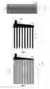
FIG. 2 schematically represents a glassy carbon substrate in the form of a comb in front view.
FIGS. 3 and 4 schematically represent a current collector consisting in the glassy carbon substrate according to FIG. 2 covering by an intermediate layer, respectively in front view and in cross section along A-A.
FIG. 5 schematically represents, in cross-section, an alternative embodiment of the current collector according to FIGS. 3 and 4.
FIG. 6 represents cyclic voltammograms of an electrode consisting in glassy carbon substrate in the form of a rod covered by an intermediary layer of pure lead, immersed in sulfuric acid solution at 40° C., respectively at 100 and 1700 voltametric cycles.
FIG. 7 represents an optical micrograph of a glassy carbon substrate in the form of a rod electroplated by pure lead, after a corrosion test at 40° C. during 16 h.
FIGS. 8 and 9 represent the evolution of charge-discharge current and potential of tubular-plate electrodes, respectively assembled with lead-tin electroplated glassy carbon substrate in the form of a rod and with cast lead-2.8% wt antimony material in the form of a rod.
DESCRIPTION OF PARTICULAR EMBODIMENTS
As represented in FIG. 1, an electrode 1 for lead-battery comprises a current collector 2 covered by an active layer 3 of lead-containing paste. The current collector 2 is formed by a glassy carbon substrate 4 on which is deposited an intermediate layer 5. The glassy carbon substrate 4 has preferably a thickness comprised between 1 mm and 3 mm whereas the thickness of the intermediate layer 5 is advantageously comprised between 50 μm and 200 μm.
The glassy carbon material is also called vitreous carbon, glassy polymeric carbon or vitreous polymeric carbon. The glassy carbon is a special form of carbon. It is a low-porous carbon. Thus, the glassy carbon substrate 4 comprises pores but the volume of these pores only represent between 0% and 10% of the apparent volume of the substrate. More particularly, the ratio between the volume of pores and the apparent volume is comprised between 1% and 6%. In addition, the glassy carbon material presents high electric conductivity property and mechanical properties similar to those of the glasses (hardness, capacity to polish the surface, etc). It has also a very high chemical resistance and it is electrochemically stable in a wide range of polarization potentials. Recycling of lead-acid batteries that comprise a glassy carbon substrate can be done by all existing technologies used for recycling of traditional lead-acid batteries. The glassy carbon substrate can be separated and used in other applications in the form of powder or subjected to incineration together with the rest of the plastic components of the battery (boxes, separators, etc).
The document JP2158057 cited in the state of the art has already proposed an electrode for a bipolar lead-storage battery comprising a glassy carbon plate. However the surface of the glassy carbon plate is covered by a layer of SnO2 or by a layer of Ti4O7 presenting some major drawbacks.
It has been surprisingly found that covering the glassy carbon substrate 4 by an intermediate layer 5 made by lead or by a lead-based alloy allows remedying to the drawbacks of the document JP2158057. In addition, the intermediate layer 5 must be a compact layer, i.e. a non-porous layer. The preferred lead-based alloy is an alloy consisting in lead and tin and more particularly a lead-tin alloy comprising 2.5 weight percents in total weight of the elements containing in the intermediate layer.
Such an intermediate layer 5 improves the adhesion of the active material paste on the current collector 2. The electrode is also more stable when deep discharge conditions are applied. In addition, the fact that the intermediate layer 5 contains tin is advantageous because tin prevents the electrode from the Predominant Capacity Loss (PCL) effect due to formation of highly resistive layer of PbO and PbOn with 1<n<2 in the corrosion layer. In fact, Sn(II) and Sn(IV) ions act as doping agents in the crystal lattice of PbO and PbOn with 1<n<2 and they decrease substantially the ohmic resistance of these two lead oxides that correspond to the compounds of the corrosion layer formed on the surface of the positive current collector during the implementation of the lead-acid battery. The presence of tin in the intermediate layer 5 also improves its mechanical resistance. However, the tin content in the intermediate layer 5 is preferably limited to 2.5 weight % because when the tin content in a lead-based alloy is more than 2.5%, its anodic corrosion rate increases markedly.
The following steps preferably produce such an electrode:
-
- formation of the glassy carbon substrate 4 by plastic molding of a thermosetting resin in a predetermined shape followed by carbonizing the thermosetting resin in inert atmosphere,
- formation of the intermediate layer 5 by electroplating of the whole of the surface of the glassy carbon substrate 4 with lead or lead-based alloy
- and formation of the active layer 3 by covering the intermediate layer 5 with a lead-containing paste.
The thermosetting resin can be a phenol-formaldehyde resin, a furfural alcohol resin, a polyester resin, an epoxy resin or a mixture of them. Carbonizing the thermosetting resin is achieved by heat treatment.
More particularly, the formation of the glassy carbon substrate 4 is followed by a surface treatment step of the glassy carbon substrate 4. The surface treatment step comprises:
-
- a mechanical treatment, for instance a sandblasting or a similar treatment in order to roughen the surface of substrate 4. In fact, the quality of the intermediate layer 5 is partly defined by the mechanical treatment.
- an electrochemical anodic etching of the glassy carbon surface. For instance, the etching conditions are the followings: Use of an alkaline solution of 1M NaOH, with an operation time of 10 min and an anodic current density of 20 mA/cm2. During this operation, the glassy carbon substrate is cleaned and additionally roughened at sub-microlevel.
- and a water rinsing to remove the alkaline solution.
In addition, the tab of the glassy carbon substrate 4, used as connection element, is advantageously electroplated with copper. Electroplating the tab with copper ensures the quality of the cast on strap connection. In fact, the glassy carbon substrate cannot be wetted in liquid metals and copper has a melting temperature much higher than the lead and is nearly insoluble in it. Suitable conditions for the copper electroplating operation can be the following:
-
- an electrolyte bath comprising 250 g.L−1 of CuSO4.5H2O and 70 g.L−1 of H2SO4,
- a cathodic current density of 40 mA/cm2,
- a temperature comprised between 20° C. and 25° C.
Moreover, the application of pulse current improves the quality of the copper layer. Suitable pulse current regime is for instance obtain by applying a cathodic current with a density of 60 mA/cm2 during 6 s and then an anodic current with a density of 60 mA/cm2 applied during 1 s.
An operation time of 30 min allows obtaining a copper layer deposited on the tab having a thickness of about 25 μm. The tab electroplated by copper is then rinsed with water.
The intermediate layer 5 is then formed by electroplating at least the whole of the surface of the glassy carbon substrate 4 with lead or lead-based alloy. This step is the most critical operation of the process. It is in particular necessary to choose an electrolyte enabling the highest adhesion strength of the intermediate layer 5 to the glassy carbon substrate 4 and a constant thickness of the intermediate layer 5 to be obtained. An intermediate layer 5 made of 2.5% Sn—Pb alloy can be formed by using an electrolyte comprising Pb(II) salt of the 4-hydroxybenzenesulfonic acid (Pb(p-C6H4OHSO3)2) and Sn (II) salt of the 4-hydroxybenzenesulfonic acid (Sn(p-C6H4OHSO3)2) and p-phenolsulfonic acid (p-C6H4OHSO3H). The weight percent of the tin is about 2.5% of the total weight of metals containing in the electrolyte in the electrolyte. In a particular embodiment, the electrolyte can be obtained by mixing:
-
- 140 g.L−1 of Pb(p-C6H4OHSO3)2,
- 40 g.L:−1 of p-C6H4OHSO3H
- 4 g.L−1 of Sn(p-C6H4OHSO3)2
- and 4 g.L−1 of gelatin.
The electroplating step can be performed with:
-
- a cathodic current density of 10 mA/cm2,
- a temperature of 20-30° C.
- and an operation time of 85 or 190 minutes.
Moreover, the application of a pulse current during the electroplating step improves additionally the homogeneity of the layer. The pulse current characteristics can be as follows:
-
- cathodic current amplitude=20 mA/cm2,
- ton=1 s
- and toff=1 s.
For instance, with an electroplating step performing during 85 minutes, the intermediate layer 5 has a thickness about 50 μm (+/−2%). This thickness is sufficient for a current collector used in a negative electrode. For a current collector used in a positive electrode, the operation time can be doubled in order to deposit an intermediate layer 5 having a thickness between about 100 μm and 200 μm (+/−2%).
Once the intermediate layer 5 is formed, the current collector is rinsed with water and dried on air flow. Then, the active layer 3 can be formed on the intermediate layer 5 by depositing the lead-containing paste in order to form the electrode. The lead-containing paste can be obtained by mixing PbO (75%) with H2O (15%) and H2SO4 (10%).
Such a process presents the advantage to provide an electrode having improved mechanical and electrical connection between the lead-containing paste and the substrate. The interface between the substrate and the intermediate layer is also stabilized even if deep discharge conditions are applied.
Moreover, the electrodes for lead-acid battery can have any known shape. For instance, the glassy carbon substrate can be in the form of grid or comb, in order to obtain electrodes in the form of flat plates or of tubular plates.
FIG. 2 represents more particularly a glassy carbon substrate 4 in the form of a comb designed to be used to obtain a tubular-plate electrode. The glassy carbon substrate 4 comprises a plurality of parallel branches 4a connected together by a base 4b. The base 4b also comprises a tab 6 equipped with an opening 7. FIGS. 3 and 4 represent the glassy carbon substrate 4 covered by the intermediate layer 5. In addition, copper 8 has filled the opening 7 before the intermediate layer 5 is formed. The typical diameter of the opening 7 is about 2-3 mm.
Moreover, the branches 4a of the glassy carbon substrate 4 have a round cross-section as represented on FIG. 4. This is the traditional design of a current collector used for a tubular-plate electrode.
However, the cross-section of the branches 4a can be of any type of form. The branches 4a can also have a rectangular cross-section as represented on FIG. 5 or a square cross-section or elliptic square cross-section. The form of current collector represented on FIG. 5 is also called Strap Grid Tubular Plates (SGTP). This form is advantageous because it increases substantially the performance of the corresponding lead-acid battery in comparison with the traditional design (round cross-section): The load factor of the active material is much higher and the internal resistance is decreased. In addition, manufacturing the SGTP current collectors from glassy carbon substrate as represented in FIG. 5 is also much cheaper than the corresponding traditional current collectors from glassy carbon substrate as represented in FIG. 4. This great difference comes from the difference in the characteristic thickness of both types of branches. In FIG. 5 (SGTP design), the diameter d of a branch 4a is about 1 mm or 1.5 mm and the diameter D of the branch 4a covered by the intermediate layer 5 is about 3 mm or 4 mm. In FIG. 4 (traditional design), the corresponding values are more than twice higher: d is about 3 mm and D is about 9 mm. The decreased thickness at the SGTP design reduces greatly the time of carbonization and hence the production cost.
In the tubular-plate design, the active material paste is encapsulated around each branch 4a covered by an intermediate layer 5, by means of a woven or non-woven textile tube. This tube maintains a constant pressure on the active material and prevents its softening or its non-cohesion from the current collector.
In a particular embodiment, a current collector formed by a glassy carbon rod (or branch or spine) having a diameter d of 3 mm and by an intermediate layer of pure lead having a thickness of 150 μm is immersed in sulfuric acid solution, H2SO4, at 40° C. with a density of 1.28 g/ml. It's testing in the 0.7V-1.6V potential interval vs. the potential of Ag/Ag2SO4. FIG. 6 shows the corresponding cyclic voltammetry curves A and B, for 100 cycles and 1700 cycles. The curves A and B do not differ from the corresponding curves of a cast lead electrode used in the state of the art.
During this test, the intermediate layer of pure lead is subjected both to cathodic dissolution and anodic corrosion attack at elevated temperature. After 1700 cycles, which correspond to a test period of 16 hours, the current collector is washed, dried and embedded in an epoxy resin 9. Its cross-section is polished and subjected to a metallographic observation as represented in FIG. 7. It can be seen that the intermediate layer 5 is homogeneous and intact. The thickness of the corrosion layer 10 is also homogeneous and there aren't cracks and pits.
In another embodiment, glassy carbon branches covered by an intermediate layer of lead-tin having a thickness of 50 μm, with a diameter D of about 3 mm, were used to form a tubular-plate electrode having a diameter of about 6 mm and a theoretical capacity about 300 mA at 50% load factor of the active material. A same type of electrode is assembled by using spines cut off from commercial tubular-grids with a Pb-2.8 wt Sb alloy.
FIGS. 8 and 9 show the evolution of the current and of the positive plate potential (measured vs. Ag/Ag2SO4 reference electrode) during the 28th charge/discharge cycle. It can be seen that the electrochemical performance of the lead electroplated glassy-carbon tubular electrode is identical with the one of the lead-antimony cast spine.
The invention is not limited to the embodiments described above. More particularly, the current collector can have the form of:
-
- a grid suitable for a flat negative or positive plate electrode. With a glassy carbon substrate having a thickness of 1 mm, the production costs of the glassy carbon substrate are minimal. After the electroplating operation, the thickness of the grid increases for instance to 1.1 mm. The manufacturing of lead-acid battery plates with such thickness results in increased battery power and active materials utilization.
- a plate used in a bipolar lead-acid battery. For instance, a glassy carbon plate having a thickness of 1-1.5 mm can be completely electroplated with a lead-tin layer having a thickness of 50 μm. The plate comprises a plurality of ribs with a length of 2 mm and a typical inter-ribs dimension of 10 mm.
- a flexible foil used in a spiral-wound lead-acid battery with ultra-thin plates. For instance, the flexible foil can have a thickness of 60-180 μm and the optimal thickness of the intermediate layer is 30 μm. Further the electroplated glassy carbon foil is double side pasted with 200-250 μm layers of basic lead sulphates and water mixture (so called “paste”).
In addition, the glassy carbon material forming the substrate of an electrode according to the invention must not be confused with reticulated vitreous carbon (RVC) as disclosed in U.S. Pat. No. 7,060,391. In fact, reticulated vitreous carbon is a high-porous carbon, in which the open porosity is about 90%-95% of its apparent volume.
Claims
1-9. (canceled)
10. A method for producing an electrode for lead-acid battery comprising at least the following steps:
formation of a glassy carbon substrate by plastic molding of a thermosetting resin in a predetermined shape followed by carbonizing the thermosetting resin in inert atmosphere,
formation of a compact intermediate layer made from a lead-tin alloy with a percent of tin in the lead-tin alloy of about 2.5% in weight on at least one part of a surface of the glassy carbon substrate, by an operation of electroplating with an electrolyte comprising Pb(II) salt of the 4-hydroxybenzensulfonic acid, Sn(II) salt of the 4-hydroxybenzenesulfonic acid and p-phenolsulfonic acid,
and formation of an active layer of lead-containing paste by covering the intermediate layer with the lead-containing paste,
wherein the glassy carbon substrate presents an apparent volume and a volume of pores, the volume of pores of the glassy carbon substrate being comprised between 0% and 10% of its apparent volume.
11. The method according to claim 10, wherein formation of the glassy carbon substrate is followed by a surface treatment step of the glassy carbon substrate comprising a mechanical treatment, an electrochemical etching and a water rinsing.
12. The method according to claim 10, wherein that the glassy carbon substrate comprises a tab and wherein an electroplating operation of the tab with copper is achieved before the formation of the compact intermediate layer.
13. The method according to claim 10, wherein the volume of the pores in the glassy carbon substrate is comprised between 1% and 6% of its apparent volume.
14. The method according to claim 10, wherein the predetermined shape of the glassy carbon substrate is a comb.
15. The method according to claim 14, wherein the glassy carbon substrate comprises a plurality of branches, having a round, rectangular, square or elliptic cross-section.
16. The method according to claim 10, wherein the glassy carbon substrate has a thickness comprised between 1 mm and 3 mm.
17. The method according to claim 10, wherein the compact intermediate layer has a thickness comprised between 50 μm and 200 μm.
18. The method according to claim 10, wherein the electrolyte is obtained by mixing:
140 g.L−1 of Pb(p-C6H4OHSO3)2,
40 g.L−1 of p-C5H4OHSO3H,
4 g.L−1 of Sn(p-C6H4OHSO3)2, and
4 g.L−1 of gelatin.
Images & Drawings included:


Sources:
- United States Patent and Trademark Office - verify current appl. status at the USPTO↗
Similar patent applications:
Recent applications in this class:
- » 20230178712 2023-06-08
Lead Alloy, Positive Electrode for Lead Storage Battery, Lead Storage Battery, and Power Storage System - » 20230041652 2023-02-09
MULTI-POROUS LEAD-CARBON ELECTRODE SHEETS AND METHOD FOR MAKING THEREOF AND LEAD-CARBON BATTERIES - » 20190109324 2019-04-11
Reticulated electrode for lead-acid battery and fabrication method thereof - » 20180261831 2018-09-13
LEAD-CARBON METAL COMPOSITE MATERIAL FOR ELECTRODES OF LEAD-ACID BATTERIES AND METHOD OF SYNTHESIZING SAME - » 20110020693 2011-01-27
Electrodes for a lead acid battery and the use thereof - » 20050235472 2005-10-27
Method of manufacture of a battery and current collector
Recent applications for this Assignee:
- » 20230093841 2023-03-30
ELECTROCHEMICAL DEVICE HAVING AT LEAST ONE GELLED ELECTRODE - » 20230040169 2023-02-09
PASSIVE LOAD BALANCER - » 20220189081 2022-06-16
B0 field inhomogeneity estimation using internal phase maps from long single echo time MRI acquisition - » 20210262927 2021-08-26
Method for observing a sample in the infrared range - » 20200358254 2020-11-12
Optoelectronic device comprising a central segment tensilely strained along a first axis and electrically biased along a second axis - » 20200343435 2020-10-29
Method for producing an electronic component with double quantum dots - » 20200281799 2020-09-10
Lower limb of an exoskeleton with low power consumption - » 20200194273 2020-06-18
Method of fabricating a semiconductor substrate having a stressed semiconductor region - » 20200173950 2020-06-04
Electrochemical measurement cartridge - » 20190177838 2019-06-13
Method of forming a crystalline thin film having the formula MYusing an ALD-formed amorphous thin film having the formula MYas a precursor