Method of making and joining an aerofoil and root
US20110088261A1
2011-04-21
12/967,420
2010-12-14
✅ Patent granted
US 8,661,669 B2
2014-03-04
-
-
David Bryant | Bayan Salone
Jeffrey S. Melcher | Manelli Selter PLLC
2031-10-25
Abstract:
A ducted fan gas turbine engine aerofoil is made by electron beam welding together at least two metal sheets (10) and (12) and electron beam welding that sub assembly via an end to a root that has been manufactured in a separate operation, and then heating the whole to a temperature that will convert the electron beam welds to diffusion bonds.
Inventors:
- Ian J. Andrews 2 🇬🇧 Willington, United Kingdom
- David Rugg 2 🇬🇧 Etwall, United Kingdom
- Michael J. Wallis 2 🇬🇧 Barrow, United Kingdom
Assignee:
- ROLLS-ROYCE PLC 4,339 🇬🇧 London, United Kingdom
Applicant:
Interested in similar patents?
Get notified when new applications in this technology area are published.
Classification:
B21D53/78 IPC
Making other particular articles propeller blades; turbine blades
F01D5/147 » CPC main
Blades; Blade-carrying members ; Heating, heat-insulating, cooling or antivibration means on the blades or the members; Blades; Form or construction Construction, i.e. structural features, e.g. of weight-saving hollow blades
B23K15/0093 » CPC further
Electron-beam welding or cutting; Welding characterised by the properties of the materials to be welded
B23K15/10 » CPC further
Electron-beam welding or cutting Non-vacuum electron beam-welding or cutting
B23K20/023 » CPC further
Non-electric welding by applying impact or other pressure, with or without the application of heat, e.g. cladding or plating by means of a press ; Diffusion bonding Thermo-compression bonding
B23K20/129 » CPC further
Non-electric welding by applying impact or other pressure, with or without the application of heat, e.g. cladding or plating the heat being generated by friction; Friction welding specially adapted for particular articles or workpieces
B23K28/02 » CPC further
Welding or cutting not covered by any of the preceding groups, e.g. electrolytic welding Combined welding or cutting procedures or apparatus
B23K2101/001 » CPC further
Articles made by soldering, welding or cutting Turbines
B23K2103/10 » CPC further
Materials to be soldered, welded or cut; Non-ferrous metals or alloys Aluminium or alloys thereof
B23K2103/14 » CPC further
Materials to be soldered, welded or cut; Non-ferrous metals or alloys Titanium or alloys thereof
F05D2230/232 » CPC further
Manufacture essentially without removing material by permanently joining parts together by welding
F05D2230/233 » CPC further
Manufacture essentially without removing material by permanently joining parts together by welding Electron beam welding
F05D2230/236 » CPC further
Manufacture essentially without removing material by permanently joining parts together by welding Diffusion bonding
Y10T29/49325 » CPC further
Metal working; Method of mechanical manufacture; Impeller making; Turbomachine making Shaping integrally bladed rotor
Y10T29/49336 » CPC further
Metal working; Method of mechanical manufacture; Impeller making Blade making
Y10T29/49337 » CPC further
Metal working; Method of mechanical manufacture; Impeller making; Blade making Composite blade
Y10T29/49339 » CPC further
Metal working; Method of mechanical manufacture; Impeller making; Blade making Hollow blade
Y10T29/49968 » CPC further
Metal working; Method of mechanical manufacture; Assembling or joining by applying separate fastener with supplemental joining Metal fusion joining
B23P15/04 » CPC further
Making specific metal objects by operations not covered by a single other subclass or a group in this subclass turbine or like blades from several pieces
Description
The present invention relates to the manufacture of aerofoil blades of the kind used in ducted fan gas turbine engines, wherein the aerofoils are located via respective roots, in and about the rim of a rotary disk within a ducted fan gas turbine engine.
More specifically, the present invention has best efficacy where used in the manufacture of gas turbine engine fan blades, the aerofoils of which are hollow.
It is known to manufacture a hollow fan blade by forming two half aerofoils, one of which provides a concave exterior surface, and the other of which provides a convex exterior surface, and both include a half root portion. The formed halves are then placed in a die and heated so as to enable diffusion bonding of the halves and super-plastic expansion and separation in known manner of the interior surfaces of the joined aerofoils to cause movement of the aerofoils into their respective curved forms.
The present invention seeks to provide an improved method of making and joining a hollow aerofoil and root.
According to the present invention there is provided a method of making an at least substantially hollow aerofoil having a separately manufactured root comprises the steps of welding at least two metal sheets together about their edges, manufacturing a root having a surface shaped to receive an end of said joined sheets, welding said end to said surface, and then holding the resulting assembly in holding means via said sheets and heating the assembly to convert the weld joints to diffusion bonds.
The invention will now be described by way of example and with reference to the accompanying drawings in which:
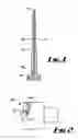
FIG. 1 is a longitudinal cross section through an aerofoil on line 1-1 of FIG. 2.
FIG. 2 is a diagrammatic sketch of a ducted fan gas turbine engine including a stage of fan aerofoils in accordance with the present invention.
Referring to FIG. 1. two sheets of metal, 10 and 12, which may be titanium or aluminium, are welded together around their edges 14. A third, much thinner metal sheet 16 of the same material as sheets 10 and 12, is trapped between sheets 10 and 12, and is further fixed by the weld referred to hereinbefore. A root member 18 that has been manufactured separate from the sheets 10, 12 and 16, is provided with a surface 20 to which, via an end, the assembly of sheets 10, 12 and 16 is fixed by e.g. electron beam welding, or linear friction welding. Root member 18 is so shaped as to be a sliding fit in a respective groove in the rim of a fan disk 22 of engine 24 in FIG. 2.
All of the parts making up the assembly are of a common material e.g. titanium or aluminium, and in the present example of the invention, it is intended that they be diffusion bonded after the welding operation. However, where thin plate 16 is used, lengthwise strip portions thereof are later required to stretch in opposing directions laterally of the sheet length, so as to provide a stiffening member for the aerofoil.
Therefore, a number of strips of a diffusion bond preventative such as Yttria are glued on to each side of sheet 16 prior to its insertion between sheets 10 and 12.
When the assembly is completed as described so far, it is placed in a suitable die which will enable forming sheets 10 and 12 into an aerofoil shape, and subjected to heat and temperature, the magnitudes of both of which are well known in the diffusion bonding and super-plastic forming field. Piping is connected to the interior of the sheets and an inert gas pumped in so as to cause sheets 10 and 12 to move away from each other to form the aerofoil shape dictated by the die, and simultaneously pull spaced portions of sheet 16 in opposing directions, to form the stiffening member. Also effected is the conversion of all of the welded joints peripherally of the sheets and between the ends of the sheets and root 18 to diffusion bonds, wherein material from each part migrates across the joint interface and eliminates it.
Attaching the root 18 to sheets 10, 12 and 16 at the stage in the process described provides the advantage that the following diffusion bonding process relieves stresses that are generated in the joint area during welding, thus obviating the need to perform a separate operation to achieve that effect. Further, it has been found that the resulting strength of the finished article is such that thinner sheets may be used without detriment.
Exclusion of sheet 16 will enable the manufacture of a completely hollow aerofoil having a root attached in the manner as described with reference to FIG. 1. In this example, that surface on one of the sheets that will be an interior surface when the two sheets are assembled, will have yttria applied to that area not required to diffusion bond.
An alternative method of manufacturing an aerofoil blade and root, is to weld sheets 10 and 12, or sheets 10, 12 and 16 together as described hereinbefore, and then super-plastically form them into the desired aerofoil shape, prior to welding them to root 18. The finished aerofoil can then be welded to root 18. The whole will then be heated to achieve conversion of the root weld to a diffusion bond, again as described hereinbefore.
A further alternative method of manufacturing an aerofoil blade and root, is to weld sheets 10 and 12, or weld sheets 10 and 12 and 16, together as described hereinbefore, and then to diffusion bond them together, prior to welding them to the root 18. The sheets 10 and 12, or the sheets 10, 12 and 16 are then super-plastically formed into the desired aerofoil shape. The heating used by the super-plastic forming process relieves stresses in the joint area during welding and to form a diffusion bond.
Claims
1-8. (canceled)
9. A method of making an at least substantially hollow aerofoil having a separately manufactured root for locating the hollow aerofoil on a rotor disk, the method comprising the steps of:
providing at least two metal sheets having edges;
welding the at least two metal sheets together about their edges;
placing the at least two metal sheets in a die having inner opposed respective aerofoil suction and pressure surfaces;
heating the at least two metal sheets and subjecting the interior thereof to a pressure sufficient to expand the metal sheets into the respective die inner surfaces so as to adopt an aerofoil form and to convert the weld joint between the joined metal sheets to a diffusion bond;
manufacturing a root having a surface shaped to receive an end of said joined metal sheets;
welding said end of the diffusion bonded metal sheets to said surface of the root to form an assembly; and
heating the diffusion bonded metal sheets and root assembly to convert the weld joint between the diffusion bonded metal sheets and the root to a diffusion bond.
10. A method of making an at least substantially hollow aerofoil according to claim 9, wherein only two metal sheets are used in the making of said aerofoil, at least one of which has a diffusion bond preventing material applied all over that surface which on assembly of the two metal sheets defines an interior surface of said assembly.
11. A method of making an at least substantially hollow aerofoil according to claim 9, wherein three metal sheets are used in the making of said aerofoil, the central metal sheet being thinner than the outer metal sheets, the central sheet having strips of diffusion bond preventing material applied to both sides thereof, the positions of said strips on one side of said central metal sheet being staggered with respect to the positions of the strips on the other side of the central metal sheet.
12. A method of making an at least substantially hollow aerofoil according to claim 9, wherein the welding of said end of the joined metal sheets to said surface of the root comprises election beam welding and friction welding.
13. A method of making an at least substantially hollow aerofoil according to claim 10, comprising pumping an inert gas between the metal sheets so as to expand the metal sheets against respective opposing inner surfaces of said die and cause them to adopt a corresponding aerofoil form.
14. A method of making an at least substantially hollow aerofoil according to claim 11, comprising pumping an inert gas between each outer metal sheet and the respective opposing sides of said central metal sheet so as to expand said outer metal sheets against respective opposing inner surfaces of said die and cause them to adopt a corresponding aerofoil form and to cause portions of the central metal sheet to superplastically extend in a staggered manner so as to form an aerofoil stiffening structure.
15. A method of making an at least substantially hollow aerofoil having a separately manufactured root for locating the hollow aerofoil on a rotor disk, the method comprising the steps of:
providing at least two metal sheets having edges;
welding the at least two metal sheets together about their edges;
diffusion bonding the welded metal sheets together;
manufacturing a root having a surface shaped to receive an end of said joined metal sheets;
welding said end of the diffusion bonded metal sheets to said surface of the root to form an assembly;
placing the diffusion bonded metal sheets and root assembly in a die having inner opposed respective aerofoil suction and pressure surfaces; and
heating the diffusion bonded metal sheets and root assembly and subjecting the interior thereof to a pressure sufficient to expand the metal sheets into the respective die inner surfaces so as to adopt an aerofoil form and to convert the weld joint between the diffusion bonded metal sheets and the root to a diffusion bond.
16. A method of making an at least substantially hollow aerofoil according to claim 15, wherein only two metal sheets are used in the making of said aerofoil, at least one of which has a diffusion bond preventing material applied all over that surface which on assembly of the two metal sheets defines an interior surface of said assembly.
17. A method of making an at least substantially hollow aerofoil according to claim 15, wherein three metal sheets are used in the making of said aerofoil, the central metal sheet being thinner than the outer metal sheets, the central sheet having strips of diffusion bond preventing material applied to both sides thereof, the positions of said strips on one side of said central metal sheet being staggered with respect to the positions of the strips on the other side of the central metal sheet.
18. A method of making an at least substantially hollow aerofoil according to claim 15, wherein the welding of said end of the joined metal sheets to said surface of the root comprises election beam welding and friction welding.
19. A method of making an at least substantially hollow aerofoil according to claim 16, comprising pumping an inert gas between the metal sheets so as to expand the metal sheets against respective opposing inner surfaces of said die and cause them to adopt a corresponding aerofoil form.
20. A method of making an at least substantially hollow aerofoil according to claim 17, comprising pumping an inert gas between each outer metal sheet and the respective opposing sides of said central metal sheet so as to expand said outer metal sheets against respective opposing inner surfaces of said die and cause them to adopt a corresponding aerofoil form and to cause portions of the central metal sheet to superplastically extend in a staggered manner so as to form an aerofoil stiffening structure.
21. A method of making an at least substantially hollow aerofoil having a separately manufactured root for locating the hollow aerofoil on a rotor disk, the method comprising the steps of:
a) providing at least two metal sheets having edges;
b) welding the at least two metal sheets together about their edges;
c) diffusion bonding the welded metal sheets together;
d) manufacturing a root having a surface shaped to receive an end of said joined metal sheets;
e) welding said end of the diffusion bonded metal sheets to said surface of the root to form an assembly;
f) placing the metal sheets in a die having inner opposed respective aerofoil suction and pressure surfaces;
g) heating the metal sheets and subjecting the interior thereof to a pressure sufficient to expand the metal sheets into the respective die inner surfaces so as to adopt an aerofoil form; and
h) converting the welded joint between the diffusion bonded metal sheets and the root to a diffusion bond.
22. A method of making an at least substantially hollow aerofoil according to claim 21, comprising performing step f) before step c), performing steps c) and g) concurrently and performing step h) after steps c) and g).
23. A method of making an at least substantially hollow aerofoil according to claim 21, comprising performing steps e), f) and g) sequentially and performing steps g) and h) concurrently.
24. A method according to claim 21, wherein the metal sheets comprise aluminum or titanium.
Images & Drawings included:
Sources:
- United States Patent and Trademark Office - verify current appl. status at the USPTO↗
Similar patent applications:
- » 20060021222
Method of making and joining an aerofoil and root
Recent applications in this class:
- » 20250264024 2025-08-21
HIGH PRESSURE TURBINE BLADE DOUBLE SCARF CUT - » 20250257660 2025-08-14
COMPOSITE AIRFOIL ASSEMBLY HAVING A COMPOSITE AIRFOIL AND SPAR - » 20250250900 2025-08-07
AEROFOIL STRUCTURE FOR A GAS TURBINE ENGINE - » 20250243762 2025-07-31
BLADE, PROCESSING SYSTEM AND PROCESSING METHOD - » 20250198292 2025-06-19
BLADE CONFIGURED FOR IMPACT TOLERANCE - » 20250198291 2025-06-19
VARIABLE RIM WIDTH TURBINE BLADE ATTACHMENT - » 20250163811 2025-05-22
ADDITIVELY MANUFACTURED ARTICLES HAVING A MICROSTRUCTURE WITH A HIGH GAMMA-PRIME VOLUME FRACTION - » 20250129721 2025-04-24
Multi-Zone Blade Fabrication - » 20250109690 2025-04-03
TURBINE ENGINE WITH COMPLIANT AXIAL RETAINER - » 20250012192 2025-01-09
COMPOSITE AIRFOIL ASSEMBLY FOR A TURBINE ENGINE
Recent applications for this Assignee:
- » 20250293588 2025-09-18
POWER ELECTRONICS CONVERTER - » 20250293575 2025-09-18
GAS TURBINE ENGINE - » 20250290665 2025-09-18
HEATING DEVICE, HEATING APPARATUS AND APPARATUS FOR PROVIDING A FLOW OF GASEOUS HYDROGEN - » 20250290433 2025-09-18
SHROUD OF GAS TURBINE ENGINE AND METHOD OF MANUFACTURING THEREOF - » 20250290426 2025-09-18
GAS TURBINE ENGINE WITH RELATIVE CLOCKING OF BIFURCATIONS - » 20250286483 2025-09-11
DETECTING ROTOR DEMAGNETIZATION - » 20250283431 2025-09-11
FUELDRAULIC HEAT MANAGEMENT SYSTEM - » 20250283429 2025-09-11
HYDROGEN FUELLED GAS TURBINE ENGINE - » 20250283428 2025-09-11
HYDROGEN FUELLED GAS TURBINE ENGINE - » 20250277473 2025-09-04
HYBRID TRANSMISSION COMPONENT FOR A GAS TURBINE ENGINE