EQUIPMENT OF CONTINUING PNEUMATIC ELECTRIC IMPULSE
US20110095543A1
2011-04-28
12/673,209
2008-08-22
Abstract:
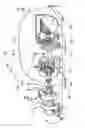
Patent of utility model for an EQUIPMENT OF CONTINUING PNEUMATIC ELECTRIC IMPULSE composed of vacuum chamber with metallic oval structure 1, where two generators 10 and 11 are coupled and fastened, through the axle 9 regarding the generator 10, with electric exciter 14 and pneumatic piston 19 that commands the equipment start-up; through generator 11 with electric exciter 15, feeding an electric motor 12 with pneumatic command 20 and field coil 22 performing electric disconnection of the motor set and generator 18, providing absolute vacuum 13, giving command in pneumatic piston 19 and electric motor 12, generating electric power. Through the electric-magnetic coupling 5, (FIG. 2) the vacuum pump 3 is located producing vacuum as in the first stage of the pneumatic turbine 2 with second stage in the turbine 6 generating high pressure for start-up, and turbocompressor of compressed air 4, feeding the reservoir of the tubular structure 7 with fastening bracket 17 and relief valve with calibration spout 16 and transportation handle dovetail 8.
Assignee:
- FERNANDO AUGUSTO PANCHECO DA CRUZ 1 🇧🇷 VILA SANTA CRUZ, ITATIBA, Brazil
Interested in similar patents?
Get notified when new applications in this technology area are published.
Classification:
H02K53/00 » CPC main
Alleged dynamo-electric
H02K7/18 IPC
Arrangements for handling mechanical energy structurally associated with dynamo-electric machines, e.g. structural association with mechanical driving motors or auxiliary dynamo-electric machines Structural association of electric generators with mechanical driving motors, e.g. with turbines
F03B17/04 IPC
Other machines or engines using hydrostatic thrust Alleged
Description
BACKGROUND OF THE INVENTION
The present patent of utility model has as the purpose a model of EQUIPMENT OF CONTINUING PNEUMATIC ELECTRIC IMPULSE for use at areas of difficult access to the electric line and of easy transportation, and which original construction was given to, viewing to improve its utilization and efficiency as compared with the existing similar ones.
Ways for generation of energy are already known, such as: motor-generators put in motion by: Gasoline, Alcohol, Diesel, Gas. Nuclear, Solar, Hydroelectric Energy Generators and also the energy produced by wind generators.
BRIEF SUMMARY OF THE INVENTION
In spite of the broad utilization of those types of energies, some inconveniences can be attributed to them as for example, in the case of the motor-generated energy that, due to the fact that the user must regularly fuel the equipment, there is some cost of refueling, as well as there is also the discharging of polluting gases to the atmosphere, and other aforementioned energy types are utilized in projects of high cost and they are of difficult access and transportation for the user.
Taking into account those problems, and with the purpose of overcoming them, it was developed the layout of an equipment of continuing pneumatic electric impulse, that is the subject matter of the present patent, which consists of an alternative energy system through a pneumatic system.
That way for construction of the equipment solves the inconveniences as pointed out, considering that it provides a clean energy, working at any gravitational location, being of easy transportation, and meeting the needs where there are areas of difficult access to the electric lines, as well as to energy production plants, due to the fact of not existing the need of utilization of combustibles such as: Gasoline, Alcohol, Diesel, Gas that are pollutants for the atmosphere, thus the user will not have to fuel or refuel its equipment and, consequently, it will help the ecosystem.
BRIEF DESCRIPTION OF THE DRAWINGS
The attached drawings show the layout of an equipment of continuing pneumatic electric impulse, being the subject matter of the present patent, on which.
The FIG. 1 shows, as a cutting view, the vacuum chamber with two generators and an electric motor;
The FIG. 2 shows the turbine with its coupling between the axle ends;
The FIG. 3 shows the closed vacuum chamber;
The FIG. 4 shows the turbine externally coupled to the axle;
The FIG. 5 shows the tubular structure and the compressed air reservoir;
The FIG. 6 shows the cutting view of the electric motor carcass with the magnetic field coils;
The FIG. 7 shows the axle with the motor and generator inductors;
The FIG. 8 shows the cutting view of the generator carcass with field coil and piston with pneumatic command;
The FIG. 9 shows the axle with the inductor of the generator;
The FIG. 10 shows the turbine being uncoupled from the axle with magnetic-electric coupling.
DETAILED DESCRIPTION OF THE PREFERRED EMBODIMENTS
In conformity with what is shown on the figures as listed above, the model of continuing pneumatic electric impulse equipment, being the subject matter of the present patent, consists of vacuum chamber with oval metallic structure 1, where two generators 10 and 11 are coupled and fastened, through the axle 9 the generator 10 with electric exciter 14 and pneumatic piston 19 that commands the start-up of the equipment, through the generator 11 with electric exciter 15 that feeds the electric motor 12 with pneumatic command 20 and field coil 22 performing the electric closing of the motor and generator set 18 that, on its side, it provides an absolute vacuum 13, giving command to pneumatic piston 19 and electric motor 12, generating the electric power.
Through the magnetic-electric coupling 5, (FIG. 2), the vacuum bomb is located 3, which produces vacuum, in the first stage of the pneumatic turbine 2 with second stage in the turbine 6 producing high pressure for the start-up, and turbocompressor of compressed air 4 that feeds the reservoir of the tubular structure 7 with fastening bracket 17 and relief valve 2 with calibration spout 16 and transportation handle dovetail 8.
Claims
What is claimed is:1. “EQUIPMENT OF CONTINUING PNEUMATIC ELECTRIC IMPULSE” composed of vacuum chamber with oval metallic structure (1), fastened by two generators (10), with electric exciter (14) and piston of pneumatic command (19) for start-up of the equipment, it feeds electric motor (12) with field coil (22) producing the electric closing through the generator (18) providing absolute vacuum (13) giving command to the pneumatic piston of the generator (11) and to the electric motor (20) that passes by the electric exciter (11) through the axle (9) and generator (10) with electric exciter (14) and pneumatic piston (19) commanding the equipment start-up through generator (11) with electric exciter (15) that feeds electric motor (12) with pneumatic command (20) and field coil (22) performing the electric closing of the motor and generator set (18) providing an absolute vacuum (13), commanding pneumatic piston (19) and electric motor (12), generating the electric power. Through the magnetic-electric coupling, (FIG. 2) the vacuum bomb is located (3) in the first stage of the pneumatic turbine (2) with second stage in the turbine (6) generating high pressure for start-up, and turbocompressor of compressed air (4) that feeds the reservoir of the tubular structure (7) with fastening bracket (17) with relief valve (21), calibration spout (16) and transportation handle dovetail (8).
Images & Drawings included:


Sources:
- United States Patent and Trademark Office - verify current appl. status at the USPTO↗
Recent applications in this class:
- » 20250079965 2025-03-06
Electric vehicle drive mechanism for driving multiple alternators chain - » 20250062671 2025-02-20
DEVICES AND METHODS OF MAGNIFYING POWER OUTPUT TO POWER INPUT - » 20250007381 2025-01-02
SELF POWERED ELECTRIC GENERATOR DEVICE - » 20240421686 2024-12-19
Centripetal magnet accelerator utilizing magnets to produce rotational motion for generating electricity - » 20240372453 2024-11-07
Generator for clean, renewable, and sustainable power generation - » 20240291369 2024-08-29
Vertical Propulsion Magnetic Generation Turbine - » 20240171056 2024-05-23
ELECTRIC CIRCULATORY LEVERAGE DRIVE METHOD AND APPARATUS - » 20230396140 2023-12-07
Energy transformer - » 20230378863 2023-11-23
Apparatus For Moving A Movable Module Thereof Based On Magnetic Interactions - » 20230336066 2023-10-19
Spiral Magnetic Engine