IMPROVED HAIR DRIER
US20110219636A1
2011-09-15
13/129,792
2009-11-19
Abstract:
There is a hair drier which includes an air nozzle (1) having an air inlet (3) in communication with an air outlet (5). The nozzle is adapted for fan forced passage of air from said inlet (3) to exit said outlets. There is a motive power unit (8) remote from said nozzle (1) to power said fan forced passage of air. The motive power unit is operable from control means (12) associated with said nozzle.
Interested in similar patents?
Get notified when new applications in this technology area are published.
Classification:
A45D20/10 » CPC main
Hair drying devices; Accessories therefor; Hot-air producers heated electrically Hand-held drying devices, e.g. air douches
A45D20/12 IPC
Hair drying devices; Accessories therefor; Hot-air producers heated electrically; Hand-held drying devices, e.g. air douches Details thereof or accessories therefor, e.g. nozzles, stands
Description
FIELD OF THE INVENTION
This invention relates to drying apparatus. More particularly, although not exclusively it discloses an improved form of hair drier for use in commercial applications.
BACKGROUND TO THE INVENTION
Conventional handheld hair driers typically comprise a cylindrical body or case with an air outlet at one end and an air inlet at the other. The drier incorporates an electric motor operated fan to provide an airstream through the casing together with an electric resistance heater such a nichrome wire element which disposed in the airstream adjacent the outlet. There is also a handle extending below the casing with thumb controls for fan speed and air temperature. Such devices have been known for many years and are generally reliable in terms of operation and performance. One serious disadvantage however is the weight of such prior art driers which is caused chiefly by the inclusion of the relatively heavy fan motor in the handheld case. While this may not be so noticeable during occasional short term domestic use professional hairdressers who employ handheld driers for many hours each day find them laborious and tiring to use. This can leave an employer exposed to employee claims for strain injury. Also, conventional handheld hair driers with the incorporated electric motor and fan are noisy and during use are held close to a client's ears. This causes discomfort and annoyance.
SUMMARY OF THE INVENTION
It is therefore an object of this invention to ameliorate the aforementioned disadvantage and accordingly a hair drier apparatus is disclosed which includes an air nozzle having an air inlet in communication with an air outlet, said nozzle being adapted for fan forced passage of air from said inlet to exit said outlet wherein a motive power unit is provided remote from said nozzle to power said fan forced passage of air, said motive power unit being operable from control means associated with said nozzle.
Preferably said motive power unit is adapted for wall mounting.
Preferably the air nozzle includes a heater through which the air passes before exiting said nozzle.
Preferably said control means are associated with said nozzle.
It is further preferred that said heater is a resistance wire element located immediately upstream of said outlet.
It is further preferred that said heater is operable from said control means.
It is further preferred that said motive power unit is adapted to supply one or more air nozzles.
BRIEF DESCRIPTION OF THE DRAWINGS
Currently preferred embodiments of the invention will now be described with reference to the attached representations in which:
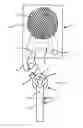
FIG. 1 is an exterior schematic view of the motive power unit and end view of the air nozzle according to a first embodiment of said invention,
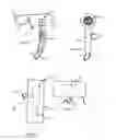
FIGS. 2 and 3 are side and rear elevation views of the air nozzle of FIG. 1,
FIGS. 4 and 5 exterior side elevation and plan views of the motive power unit of FIG. 1
FIG. 6 is an exterior schematic view showing a motive power unit and end view of the air nozzle according to a second embodiment of said invention,
FIGS. 7 and 8 are cross-section side and rear elevation views of the handheld air nozzle of FIG. 6,
FIGS. 9 and 10 are exterior side elevation and plan views of the motive power unit of FIG. 6,
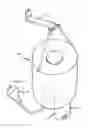
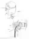
FIGS. 11 and 12 are exterior schematic and cross-section elevation views of the motive power unit and air nozzle according to a third embodiment of the invention, and
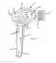
FIGS. 13 and 14 are exterior schematic and cross-section elevation views of the motive power unit and air nozzle according to a fourth embodiment of the invention.
DETAILED DESCRIPTION OF THE PREFERRED EMBODIMENTS
In the external views the interior components of the hair drier apparatus referred to are indicated by broken lines.
Referring first to FIGS. 1 to 3 there is an air nozzle indicated generally as 1 which is adapted for handheld operation as with handle 2. The nozzle/handle assembly includes an air inlet 3 with adjacent filter screen at one end which is in communication with an air outlet 5. There is also a nichrome wire resistance heating element 6 intermediate said inlet and outlet. An air passage is thereby defined in the nozzle from the inlet 3 through the filter screen to the heater 6 and outlet 5. The inlet 3 is connected to one of two supply outlets 7 in a remote wall mounted motive power unit indicted generally as 8. The connection is by means of a flexible conduit 9 and electrical control cables 10. These cables 10 connect with the heating element 6 adjacent the nozzle outlet 5 as well as a circuit board 11 within the motive power unit and control switches 12 on the handle 2.
The motive power unit includes a suitably shaped housing 13 which is adapted for mounting to a wall or other convenient support structure (not shown) in a hair salon. It comprises a fan motor 14 fan blades 15, intake filter 16, electrical circuit board 11 and two air outlets 7 as mentioned earlier.
Individual controls 12 on the handle of each nozzle ensure that the hairdresser could adjust air flow and air temperature as required via the electrical cables 10 running parallel with each air conduit. As the electrical control circuitry used in the apparatus would be similar to that used in existing hair driers it will not be described in detail. The design and construction of such circuitry would be known to a person skilled in the art.
With the second, third and fourth embodiments of the invention as shown in FIGS. 6 to 14 the main components that correspond in function to those of FIGS. 1 to 5 are identified by the same numbers which however are primed (′) (″) and (′″) to distinguish them.
In the case of the second embodiment as shown in FIGS. 6 to 10 the fan blades 15′ are located within the air nozzle intermediate the inlet 3′ and outlet 5′ and upstream of the heater 6′. The fan blades 15′ are driven from a remote motive power unit with motor 14′. The drive is via a flexible rotating drive cable 17 of any suitable design. Although not shown in the drawings this drive cable 17 and the electrical control cables 10′ are preferably encased in a common outer sheath.
With the third embodiment shown in FIGS. 11 and 12 the remote motive power unit 8″ is fitted with a mains power lead and plug 19. It may also be adapted to hang from a wall bracket 20 or the like. Within the unit is an electric motor and fan (not shown) of any suitable known design which is controlled through an electrical cable 10″ extending from the fan motor to one or more switches 12″ on the nozzle/handle assembly 1″. There is a flexible air conduit 9″ extending from the base of the handle 2″ to the underside of the motive power unit where it removably couples with a connector fitting 21. Preferably the electrical control cable 10″ is encased within the wall of the conduit 9″. Within the nozzle/handle assembly 1″ the air flow 22 from the conduit 9″ is turned by a cowling 23 at about 90 degrees and directed through a venturi type air multiplier 23A whereby it entrains additional air 24 directly from an inlet 3″ before exiting through a heater 6″ and outlet 5″. This arrangement has the effect of reducing the required air volume and pressure through the duct 9″ while increasing flow at the nozzle outlet 5″.
In the case of the fourth embodiment shown in FIGS. 13 and 14 the motive power unit 8′″ comprises a direct plug-in 25 to a conventional mains power point. Within the unit is an electric motor (not shown) of any known suitable design which is controlled by an electric cable 10′″ extending from said unit to one or more switches 12′″ on the nozzle/handle assembly 1′″. With this embodiment the fan 15′″ is mounted within the nozzle. It is driven by a rotating flexible drive cable 26 extending from said electric motor within the motive power unit 8′″ to the nozzle. Preferably it is positioned in a movable cowling 27 which may be angled upwardly with respect to the direction of air flow 27A through the nozzle outlet 5′″.This configuration enables a reduction in the curvature through which the cable 26 has to bend in order to drive the fan blades 15′″. The cowling 27 is shaped to operate as a venturi type air multiplier which entrains additional air 28 into the flow directly from intake 3′″ before exiting through a heater element 6′″ and outlet 5′″. Preferably the angle of the cowling 27 with respect to the direction of air flow 27A through the outlet 5′″ may also be changed by sliding a lever 29 as indicated by arrow 30. This has the effect of changing the efficiency of the fan 15′″ and thus the volume of air flow passing through the nozzle. This arrangement for varying the volume air flow may be in addition to or as an alternative to the electrical controls 12′″ referred to earlier.
While for simplicity of illustration only one nozzle/handle assembly is shown with each embodiment in use two or more may be fitted. For example in a professional hair salon the motive power unit may be mounted to a wall between two adjacent work stations. The flexible air ducts or drive cables would then connect the unit with individual handheld nozzles—one for each hairdresser. As the weight of the heavy fan motor is not carried in these nozzles they would be more agile, lighter and less tiring to use over a working day.
It will thus be appreciated that this invention at least in the forms of the embodiments disclosed provides a novel and inventive improvement to hair driers. Clearly however the examples described are only the currently preferred forms of the invention and a wide variety of modifications may be made which would be apparent to a person skilled in the art. For example the number of nozzles powered by the motive power unit, the shape and configuration of said nozzles and the design of the electrical controls may all be changed following further development work by the inventors.
Other optional features of a hair drier according to the invention are as follows:
-
- The heating element may be incorporated into the remote motive power unit instead of the nozzle/handle assembly in accordance with design constraints.
- The heating element may be located either upstream or downstream of the fan.
- The motive power unit and heating element may or may not be controlled by hand operated switches on the nozzle/handle assembly. The control may also be remote or fully automatic and operable for example by pressure sensors, foot activated switches etc.
- The fan may be axial flow, as shown in the embodiments or centrifugal.
- The design of the flexible drive will take into consideration speed, and torque to maximize the efficiency and minimize the size of the flexible drive, physical/mechanical restraints and rigidity etc. This would also impact on the physical dimensions of the impeller. Variations to the size and capability of the drive are also within the scope of the invention.
- The flexible drive may be of a general commercial standard or so designed to utilize modern materials to optimize its efficiency, reduce its maintenance and improve its flexibility.
- If the hair drier is to have variable flow rate of air, this may be achieved by providing a multi speed motive power unit or by having multiple fan impellers engaged as required, variable pitch impeller or variable attitudes.
- Within the design considerations of variable flexible drive through the handle to the impeller within, it should be considered that the impeller may not be in the direct line of air flow, but that the impeller may be offset from the direct line of flow, and that the air intake and air outlet are ducted in such a manner within the casing to achieve the desired air flow and within this ducting arrangement that variable air flows may be achieved through flow divisions, valves etc.
- The hair dryer may incorporate a “Cold Shot” Button.
- The heating element may be traditional electric wire wound or any other suitable means It may be positioned within the hand piece or at a remote position.
Claims
The claims:1. A hair drier apparatus which includes an air nozzle having a handle, an air inlet and an air outlet whereby said nozzle is adapted for fan forced passage of air to exit said outlet and said apparatus further including a motive power unit remote from said nozzle to power said fan forced passage of air.
2. The hair drier apparatus as claimed in claim 1 wherein said motive power unit includes a fan and said nozzle is connected to said motive power unit by a flexible air conduit.
3. The hair drier apparatus as claimed in claim 2 wherein electrical control cables are incorporated into said flexible air conduit 4
4. The hair drier apparatus as claimed in claim 1 wherein said nozzle is connected to said motive power unit by a flexible rotating drive cable which drives a fan located in said nozzle.
5. The hair drier apparatus as claimed in claim 4 wherein electrical control cables are incorporated into said flexible rotating drive cable.
6. The hair drier apparatus as claimed in claim 2 wherein said flexible air conduit connects to a venturi type air multiplier within said nozzle whereby said fan forced passage of air entrains additional air from said inlet before exiting said outlet.
7. The hair drier apparatus as claimed in claim 6 wherein said air conduit extends up through the handle and said venturi type air multiplier includes a cowling which turns said fan forced passage of air through about 90 degrees.
8. The hair drier apparatus as claimed in claim 4 wherein said fan is operatively associated with a venturi type air multiplier within said nozzle whereby said fan forced passage of air entrains additional air from said inlet before exiting said outlet.
9. The hair drier apparatus as claimed in claim 8 wherein said venturi type air multiplier includes a cowling and said fan is located within said cowling.
10. The hair drier assembly as claimed in claim 9 wherein said cowling is movable whereby the angle thereof can be changed with respect to the direction of air flow through said outlet to vary the volume of said air flow.
11. The hair drier apparatus as claimed in claim 7 wherein a heating element is located upstream of said outlet.
12. The hair drier apparatus as claimed in claim 9 wherein a heating element is located upstream of said outlet.
Images & Drawings included:


Sources:
- United States Patent and Trademark Office - verify current appl. status at the USPTO↗
Recent applications in this class:
- » 20230329410 2023-10-19
Far infrared hair dryer - » 20230270224 2023-08-31
HAIR DRYER - » 20210307472 2021-10-07
Hair dryer - » 20210267341 2021-09-02
VERTICALLY EREACTABLE AND/OR VERTICALLY ERECTABLE AND FIXABLE HAIR DRYER HOUSING AND HAIR DRYER HAVING SAME - » 20200128935 2020-04-30
Hair dryer with built-in laser diodes - » 20200008552 2020-01-09
Battery powered collapsible blow-dryer - » 20190098977 2019-04-04
Connected systems, devices, and methods including a brush and hair dryer - » 20180295964 2018-10-18
Battery Powered Hair Dryer - » 20170280848 2017-10-05
HAND HELD APPLIANCE - » 20170164709 2017-06-15
HAND HELD APPLIANCE