DEVICE AND METHOD FOR FABRICATING MICRO ARTICLES
US20110220510A1
2011-09-15
12/897,128
2010-10-04
Abstract:
A device for fabricating micro articles, which includes a first electrode plate, a second electrode plate, and a spacing component. The first electrode plate has a forming electrode, where the forming electrode correspondingly matches a cross-section of the micro article. The spacing component is disposed in between the first electrode plate and the second electrode plate, with the thickness corresponds to the thickness of the micro article. Thereby, the device is able to store the solidifiable liquid therein, where the solidifiable liquid is controlled for shaping according to the forming electrode. After the solidifiable liquid has shaped and solidified, the finished product of the micro article is attained. The present disclosure also provides a method for fabricating micro articles.
Inventors:
- Chih-Ming Wu 2 🇹🇼 Kaohsiung City, Taiwan
- Shih-Kang Fan 16 🇹🇼 Hsinchu, Taiwan
- TING-HSU LIN 1 🇹🇼 TAIPEI CITY, Taiwan
- JING-WEI LIN 1 🇹🇼 TAIPEI CITY, Taiwan
Assignee:
- National Chiao Tung University 881 🇹🇼 Hsinchu, Taiwan
Interested in similar patents?
Get notified when new applications in this technology area are published.
Classification:
C25D1/00 » CPC main
Electroforming
C25D1/10 » CPC further
Electroforming Moulds; Masks; Masterforms
C25D5/50 » CPC further
Electroplating characterised by the process; Pretreatment or after-treatment of workpieces; After-treatment of electroplated surfaces by heat-treatment
C25D1/20 IPC
Electroforming Separation of the formed objects from the electrodes with no destruction of said electrodes
C25D17/00 IPC
Constructional parts, or assemblies thereof, of cells for electrolytic coating
Description
BACKGROUND OF THE INVENTION
1. Field of the Invention
The present invention relates to a device and method for fabricating micro articles: more particularly, to a device and method for fabricating micro articles with improved efficiency and lower cost.
2. Description of the Related Art
It is well known in the art that conventional polymer manufacturing techniques include casting, injection molding, and hot embossing. All of the above techniques require molds having cavities of predefined shapes. Based on the configuration and arrangement of the cavity, the molten polymer in the mold cools and hardens to form the desired product. Moreover, the hot embossing method is the preferred technique for fabricating micro articles such as micro- or nanostructures.
Although the hot embossing technique possesses several advantages, it also suffers certain drawbacks. For one thing, the mold is subjected to very high pressure during hot embossing process. During the high pressure stamping procedure, air bubbles may be forced into the molten polymer, and thus forming gas pockets and internal voids in the structure once the polymer hardens. Moreover, in order to meet the tight tolerances required by the fabrication of micro-articles, the production for such high precision mold is both cost and time consuming.
Furthermore, during the hot embossing process, the mold may often be damaged from the high pressure exerted thereon. A mold having low wear resistance will require frequent replacement as a result, which would incur additional manufacturing cost. In addition, scrap polymer materials often remain on the mold, thus contaminating and affecting tolerances of the subsequent products. However, the removal of scraps would require additional time and cost.
To address the above issues, the inventor has proposed a solution.
SUMMARY OF THE INVENTION
The object of the instant disclosure is to provide a device and method for fabricating micro articles, which would reduce the manufacturing cost.
To achieve the above object, the device for fabricating micro articles of the instant disclosure comprises a first electrode plate, which includes a first substrate and a first electrode layer, with the first electrode layer placed at one side of the first substrate, and the first electrode layer consists a forming electrode matching to a cross-section of the micro article; a second electrode plate, which includes a second substrate and a second electrode layer, where the second electrode layer is placed at one side of the second substrate opposite of the first electrode layer; a spacing component, which is placed in between the first and second electrode plate, with the thickness of the spacing component corresponding to the thickness of the micro article.
To achieve the above object, the method for fabricating micro articles of the instant disclosure comprises the steps of disposing a pumped fluid and a surrounding fluid in between a first electrode plate and a second electrode plate, where the surrounding fluid surrounds the pumped fluid and is immiscible to the pumped fluid; applying electric voltage to the first electrode plate and the second electrode plates, with the pumped fluid being forced to flow onto a forming electrode of the first electrode plate, where the pumped fluid is shaped accordingly, with the forming electrode matching to a cross-section of the micro article; solidifying the pumped fluid; and extracting the solidified pumped fluid.
Another method of fabricating micro articles of the instant disclosure comprises the steps of disposing a pumped fluid and a surrounding fluid in between a first electrode plate and a second electrode plate, where the surrounding fluid surrounds the pumped fluid but are immiscible; applying electric voltage to the first electrode plate and the second electrode plate, with the pumped fluid being forced to flow onto a forming electrode of the first electrode plate, where the pumped fluid is shaped accordingly; solidifying the surrounding fluid; and extracting the solidified surrounding fluid.
Regarding the micro article, the instant disclosure has several advantages. For instance, no complex molds nor forming tools are needed. Thus, the manufacturing time and cost are reduced.
In order to further appreciate the characteristics and technical contents of the instant disclosure, references are hereunder made to the detailed descriptions and appended drawings in connection with the instant disclosure. However, the appended drawings are merely shown for exemplary purposes, rather than being used to restrict the scope of the instant disclosure.
BRIEF DESCRIPTION OF THE DRAWINGS
FIG. 1 shows a schematic view of a device for fabricating micro articles according to a preferred embodiment of the instant disclosure.
FIG. 2 shows an exploded view of a device for fabricating micro articles according to a preferred embodiment of the instant disclosure.
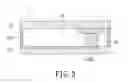
FIG. 3 shows an assembly view of a device for fabricating micro articles according to a preferred embodiment of the instant disclosure.
FIG. 4 shows a block diagram of the method for fabricating micro articles according to a preferred embodiment of the instant disclosure.
FIG. 5 shows a schematic view of a heating member for fabricating micro articles according to a preferred embodiment of the instant disclosure.
FIG. 6 shows a schematic view of a device for fabricating micro articles under ultraviolet light according to a preferred embodiment of the instant disclosure.
FIG. 7 shows a schematic view of a device for fabricating micro articles with the second electrode plate in an open position according to a preferred embodiment of the instant disclosure.
FIG. 8 shows a block diagram of another method for fabricating micro articles according to a preferred embodiment of the instant disclosure.
FIG. 9 shows a schematic view of a device for fabricating micro articles with different cross-sections according to a preferred embodiment of the instant disclosure.
DETAILED DESCRIPTION OF THE PREFERRED EMBODIMENTS
FIGS. 1 to 3 show a device for fabricating micro articles 1 according to a preferred embodiment of the instant disclosure. The device is capable of fabricating micro structures of micro to nano scale using polymer materials.
The device for fabricating micro articles 1 is basically a microfluidic system (microfluidic chip), which includes a pumped fluid 2 and a surrounding fluid 3 therein. The pumped fluid 2 can be a solidifiable liquid such as 4-hydroxybutyl acrylate (4-HBA), polyethylene glycol diacrylate (PEGDA), or other acrylic type polymers in liquid form. The surrounding fluid 3 is chosen from fluids that are immiscible with the pumped fluid 2, and has a smaller dielectric constant than the pumped fluid 2, such as air, silicone oil, or hexadecane.
An electric field may be applied to the device during fabricating processes. The electric field may cause the pumped fluid 2 to flow or change shapes due to phenomenon such as dielectrophoresis (DEP) or electrowetting-on-dielectric (EWOD). The structural characteristics of the device for fabricating micro articles 1 will be described as follows, while the method for fabricating micro articles will be discussed thereafter.
The device for fabricating micro articles 1 includes a first electrode plate 11, a second electrode plate 12, and a spacing component 13.
The first electrode plate 11 comprises a first substrate 111, a first electrode layer 112, a dielectric layer 113, and a first hydrophobic layer 114. The first substrate 111 may have a rectangular body made of glass, silicon, poly-dimethylsiloxane (PDMS), polyethylene terephthalate (PET), polyethylene naphthalate (PEN), flexible polymer materials, or other materials with good insulating property. Transparent glass is chosen in the instant embodiment as the preferred choice, because the transparent property of the glass material allows ultraviolet light from a light generating member 15 (shown in FIG. 6) to pass through un-obstructively. If a flexible polymer material is used, the first substrate 111 may be folded into a curved or a cylindrical structure (not shown).
The first electrode layer 112 is disposed at the top surface of the first substrate 111. The material composition of the first electrode layer 112 may be conductive materials such as metals (e.g., copper and chromium), conductive polymer materials, or conductive oxidized materials (e.g., indium tin oxide (ITO)). The first electrode layer 112 may comprise a plurality of separate electrodes 1121 to 1123 arranged in intervals. Functionally, the electrodes 1121 thru 1123 can be categorized as a storage electrode 1121, a forming electrode 1122, and a flow channel electrode 1123. In the instant embodiment, the two ends of the flow channel electrode 1123 are connected to the storage electrode 1121 and the forming electrode 1122 respectively.
The storage electrode 1121 is used for storing the pumped fluid 2, while the forming electrode 1122 is used for shaping the pumped fluid 2 as the electric voltage is applied. The flow channel electrode 1123 provides a bridge between the storage electrode 1121 and the forming electrode 1122. Operationally, the pumped fluid 2 flows from the storage electrode 1121 through the flow channel electrode 1123 to the forming electrode 1122. Moreover, the shape of the forming electrode 1122 is designed correspondingly in accordance to a cross-section of the micro article desired to be formed. For example, the instant embodiment shows the micro article to be a gear. Accordingly, the forming electrode 1122 is designed to replicate a gear structurally. Furthermore, the flow channel electrode 1123 may have a groove-like shape, or it may be formed by a plurality of small rectangular electrodes.
The electrodes 1121 to 1123 may be fabricated as follows. First, electron beam evaporation, physical vapor deposition, or vacuum sputtering process is used to dispose a thin film over the first substrate 111. Next, photolithography and etching process are used to remove excess materials in forming the electrodes 1121 to 1123. Alternative fabrication method includes the lift-off technique.
The dielectric layer 113 is disposed over the first electrode layer 112 on the top surface of the first substrate 111, and can be made of parylene, positive or negative photoresist materials. A deposition process follows to dispose the dielectric layer 113 over the first electrode layer 112.
The first hydrophobic layer 114 is disposed over the electric layer 113. Hydrophobic material such as Teflon is used in the deposition process to dispose over the dielectric layer 113. Also called a low friction layer, the first hydrophobic layer 114 has very low friction for allowing free movement by the pumped fluid 2.
Notably, if the pumped fluid 2 already has required dielectric and hydrophobic properties, the dielectric layer 113 and the first hydrophobic layer 114 are not required for the first electrode layer 112.
The above discussions are for the first electrode plate 11. The following discussions are related to the second electrode plate 12. The second electrode plate 12 is arranged in parallel and spaced above the first electrode plate 11. The second electrode plate 12 includes a second substrate 121, a second electrode layer 122, and a second hydrophobic layer 123.
Similar to the first substrate 111, the second substrate 121 has a rectangular body and is made of glass, silicon, poly-dimethylsiloxane (PDMS), polyethylene terephthalate (PET), polyethylene naphthalate (PEN), flexible polymer materials, or other materials with good insulating properties. Transparent glass is chosen in the instant embodiment as the preferred choice.
The second electrode layer 122 is disposed at the bottom surface of the second substrate 121. Facing the first electrode layer 112, the second electrode layer 122 covers the whole second substrate 121. The material composition of the second electrode layer 122 may be conductive materials such as metals (e.g., copper and chromium), conductive polymer materials, or conductive oxidized materials (e.g., indium tin oxide (ITO)). Electron beam evaporation, physical vapor deposition, or vacuum sputtering process is used to form the second electrode layer 122 over the second substrate 121. Like the first electrode layer 112, the second electrode layer 122 can have a plurality of separate electrodes arranged in intervals.
The second hydrophobic layer 123 is disposed under the second electrode layer 122. Hydrophobic material such as Teflon is used in the deposition process to form under the second electrode layer 122. Also called a low friction layer. the second hydrophobic layer 123 has very low friction to allow free movement of the pumped fluid 2. If the pumped fluid 2 already has required hydrophobic property, the second hydrophobic layer 123 would not be needed.
If needed, a dielectric layer can be inserted between the second electrode layer 122 and the second hydrophobic layer 123. Furthermore, the second electrode layer 122 can have a plurality of separate electrodes spaced in intervals, matching in design and position with the corresponding electrodes of the first electrode layer 112. Alternatively, the second electrode layer 122 can have different electrodes from the first electrode layer 112 to fabricate more complicated micro articles.
The above discussions are for the second electrode plate 12. The following discussions are focused on the spacing component 13. The spacing component 13 is made of an insulating material. With no structural restrictions, the spacing component 13 can be a frame as in the instant embodiment or a plurality of cylindrical members. The spacing component 13 is located in between the first electrode plate 11 and the second electrode plate 12 in separating the two, while holding the pumped fluid 2 and the surrounding fluid 3 in between the first electrode plate 11 and the second electrode plate 12. The thickness of the spacing component 13 corresponds to the thickness of the micro article. Therefore, a thicker micro article would be obtained by using a thicker spacing component 13.
Please refer to FIG. 4, which describes the steps for using the device for fabricating micro articles 1. In other words, the method for fabricating micro articles of the instant embodiment is discussed as follows.
First, or step S101, the pumped fluid 2 and the surrounding fluid 3 are disposed in between the first electrode plate 11 and the second electrode plate 12. Electric voltage is applied onto the storage electrode 1121 and the second electrode layer 122. Thereby, the pumped fluid 2 stays on the storage electrode 1121, and the surrounding fluid 3 surrounds the pumped fluid 2.
Next, or step S103, electric voltage is applied to the flow channel electrode 1123 and the forming electrode 1122 of the first electrode plate 11, and the second electrode plate 12. Thereby, the pumped fluid 2 is forced to flow from the storage electrode 1121, through the flow channel electrode 1123, to the forming electrode 1122. Based on the design of the forming electrode 1122, the pumped fluid 2 is shaped accordingly.
Next, or step S105, the shaped pumped fluid 2 is solidified. Based on the type of the pumped fluid 2, different solidification method can be used. The easiest method is to blend curing agent into the pumped fluid 2, and the pumped fluid 2 is left to solidify as time passes.
FIG. 5 shows a faster solidification process by adding heat to the shaped pumped fluid 2. In other words, the device for fabricating micro articles 1 includes a heater 14. The heater 14 can be any heat generating member that can provide heat to the first electrode plate 11 or the second electrode plate 12 or both. In turn, heat is transferred to the pumped fluid 2 and solidifies accordingly.
As shown in FIG. 6, a faster solidification process can also be achieved by shining ultraviolet light onto the pumped fluid 2 after being shaped. In other words, the device for fabricating micro articles 1 includes an ultraviolet light generating member 15. By shining ultraviolet light to the pumped fluid 2 through the first electrode plate 11 or the second electrode plate 12 or both, which are transparent, the pumped fluid 2 gradually solidifies. When shining the ultraviolet light, the light projection area is controlled such that the light only shines over the pumped fluid 2 at the area of the forming electrode 1122. Therefore, the rest portions of the pumped fluid 2 would not solidify.
Alternatively, a cooling member can be used to cool the pumped fluid 2 below the corresponding freezing temperature, thereby solidifying the pumped fluid 2. The procedure would include cooling the first electrode plate 11 or the second electrode plate 12 or both, which in turn cools the pumped fluid 2.
Next, or step S107, the solidified pumped fluid 2 is extracted. FIG. 7 shows one of the extraction techniques. The solidified pumped fluid 2 is sticking to the second electrode plate 12. By lifting the second electrode plate 12 upward, the solidified pumped fluid 2 would be moved away from the first electrode plate 11. Lastly, by separating the solidified pumped fluid 2 from the second electrode plate 12, a finished product of micro article is attained.
The above discussions describe the method for fabricating a micro article step by step. If the micro article has a plurality of different cross-sections, the device for fabricating micro articles 1 of the instant disclosure still suffice. Please refer to FIGS. 8 and 9, which explain the method for fabricating micro articles with different cross-sections. The steps continue from step S107.
First, or step S201, place the solidified pumped fluid 2 and the second electrode plate 12 on top of a thicker spacing component, defined here as a second spacing component 13A. As a result, the second electrode plate 12 becomes opposite of another first electrode plate, defined here as a third electrode plate 11A. In other words, the solidified pumped fluid 2 is in between the third electrode plate 11A and the second electrode plate 12. Structurally, the third electrode plate 11A is similar to the first electrode plate 11. Defined as a second forming electrode 1122A, the forming electrode of the third electrode plate 11A has a shape that matches a different cross-section of the micro article. The thickness of the second spacing component 13A corresponds to the thickness of the other cross-section of the micro article.
The next step, S203, is similar to step S101, where another pumped fluid, defined here as a second pumped fluid 2A, and another surrounding fluid, defined here as a second surrounding fluid 3A, are placed in between the third electrode plate 11A and the second electrode plate 12. For fluid type, the second pumped fluid 2A can be the same as the pumped fluid 2, and the second surrounding fluid 3A can be the same as the surrounding fluid 3.
The next step, S205, is similar to step S103, where electric voltage is applied to the second forming electrode 1122A of the third electrode plate 11A and the second electrode plate 12. Thereby, the second pumped fluid 2A is forced to flow to the second forming electrode 1122A. In turn, the second pumped fluid 2A is shaped according to the design of the second forming electrode 1122A, which matches to another cross-section of the micro article.
Next, or step S207, the second pumped fluid 2A is solidified and combines with the earlier solidified pumped fluid 2. Based on the type of the second pumped fluid 2A, different solidification process can be selected such as by direct solidification, heating, cooling, or ultraviolet light projection.
Lastly, or step S209, the combined structure of solidified second pumped fluid 2A and solidified pumped fluid 2 is extracted, with extraction method based on step S107. Thus, the finished product of the micro structure with a plurality of different cross-sections is formed.
Noteworthy, all above discussions are based on using the pumped fluid 2 in forming the micro articles. However, the surrounding fluid 3 can also be solidified for the fabrication process. In such scenario, the pumped fluid 2 would be a non-solidifiable material, and the surrounding fluid 3 would be a solidifiabe liquid such as a solidifiable polymer material. The shape of the forming electrode 1122 would correspond to an inner cross-section of the micro article.
In addition, the pumped fluid 2, or the second pumped fluid 2A, may be disposed directly onto the forming electrode 1122 by processes such as spraying or injection. Hence, the first electrode layer 112 would not need to include the storage electrode 1121 and the channel flow electrode 1123, which saves the manufacturing cost.
Furthermore, the number of forming electrode 1122 for the above embodiments is not restricted. The first substrate 111 may include a plurality of forming electrodes 1122. The forming electrodes 1122 may be connected or separated with same or different shapes. Thereby, a plurality of micro articles with identical or different structures can be fabricated at one time.
Based on the above discussions, the device and method for fabricating micro articles has the following characteristics:
- 1. The first electrode plate 11 (or the third electrode plate 11A) and the second electrode plate 12 are easier to manufacture in comparison to the tooling for the conventional hot embossing process. The distinction gets more significant as the scale of the micro articles becomes smaller.
- 2. Because the first electrode plate 11 and the second electrode plate 12 have no significant concave or convex structures, the solidified pumped fluid 2 or the surrounding fluid 3 has less contact surface with the first electrode plate 11 and the second electrode plate 12. Therefore, the separation process of the micro article from the first electrode plate 11 or the second electrode plate 12 is easier, with less materials be left on the first electrode plate 11 or the second electrode plate 12.
- 3. The device for fabricating micro articles 1 has no moving parts. There is no noise, vibration, or wearing parts. Thereby, the service life is longer.
- 4. The fabrication process of the micro article is very fast, with completion within several minutes. Only a small amount of electrical energy is used.
- 5. The volume of the pumped fluid 2 and the surrounding fluid 3 can be easily controlled, with only a small amount of pumped fluid 2 and the surrounding fluid 3 are needed to fabricate the micro article.
- 6. Different cross-sections and thicknesses of the micro articles can be fabricated without restrictions.
- 7. A flexible micro article can be fabricated if the solidified pumped fluid 2 or solidified surrounding fluid 3 is flexible. It can be further fabricated in flexible first substrate 111 and second substrate 121. The flexibility of the solidified fluid and the substrates do not adversely affect the ability of the fabrication.
- 8. When using the micro article as an etching mask of the etching process, the spin coating and photoresist process can be skipped during the lithography process. The total fabrication time and material usage are reduced, along with using cheaper materials. In addition, manufacturing apparatus such as lithography stepper would no long be needed, which saves manufacturing cost.
The descriptions illustrated supra set forth simply the preferred embodiments of the instant disclosure; however, the characteristics of the instant disclosure are by no means restricted thereto. All changes, alternations, or modifications conveniently considered by those skilled in the art are deemed to be encompassed within the scope of the instant disclosure delineated by the following claims.
Claims
What is claimed is:1. A device for fabricating micro articles, comprising:
a first electrode plate having a first substrate and a first electrode layer, wherein the first electrode layer is disposed on one side of the first substrate, wherein the first electrode layer having a forming electrode, wherein the forming electrode correspondingly matches a cross-section of the micro article;
a second electrode plate having a second substrate and a second electrode layer, wherein the second electrode layer is disposed on one side of the second substrate opposite to the first electrode layer; and
a spacing component disposed in between the first electrode plate and the second electrode plate, wherein the thickness of the spacing component corresponds to the thickness of the micro article.
2. The device for fabricating micro articles according to claim 1, wherein the first electrode layer has a storage electrode and a flow channel electrode; the flow channel electrode is connected to the storage electrode and the forming electrode respectively.
3. The device for fabricating micro articles according to claim 1, further comprising a heater for heating at least one of the first and the second electrode plate.
4. The device for fabricating micro articles according to claim 2, further comprising a heater for heating at least one of the first and the second electrode plate.
5. The device for fabricating micro articles according to claim 1, further comprising a cooler for cooling at least one of the first and the second electrode plate.
6. The device for fabricating micro articles according to claim 2, further comprising a cooler for cooling at least one of the first and the second electrode plate.
7. The device for fabricating micro articles according to claim 1, further comprising an ultraviolet light generating member for providing ultraviolet light to at least one of the first and the second electrode plate.
8. The device for fabricating micro articles according to claim 2, further comprising an ultraviolet light generating member for providing ultraviolet light to at least one of the first and the second electrode plate.
9. The device for fabricating micro articles according to claim 1, further comprising a pumped fluid and a surrounding fluid disposed in between the first electrode plate and the second electrode plate, wherein the surrounding fluid surrounds the pumped fluid, and wherein the two fluids are immiscible.
10. The device for fabricating micro articles according to claim 2, further comprising a pumped fluid and a surrounding fluid disposed in between the first electrode plate and the second electrode plate, wherein the surrounding fluid surrounds the pumped fluid, and wherein the two fluids are immiscible.
11. A method for fabricating micro articles, comprising the steps of:
disposing a pumped fluid and a surrounding fluid in between a first electrode plate and a second electrode plate, wherein the surrounding fluid surrounds the pumped fluid but are immiscible;
applying electric voltage to the first electrode plate and the second electrode plate for causing the pumped fluid to flow onto a forming electrode of the first electrode plate, whereby the pumped fluid is shaped according to the shape of the forming electrode, and wherein the shape of the forming electrode correspondingly matches a cross-section of the micro article;
solidifying the pumped fluid; and
extracting the product made of the solidified pumped fluid.
12. The method for fabricating micro articles according to claim 11, wherein, heat is added to the pumped fluid for solidifying the pumped fluid.
13. The method for fabricating micro articles according to claim 11, wherein, the pumped fluid is cooled for solidifying the pumped fluid.
14. The method for fabricating micro articles according to claim 11, wherein, an ultraviolet light is shined onto the pumped fluid for solidifying the pumped fluid.
15. The method for fabricating micro articles according to claim 11, wherein the extraction of the product of the solidified pumped fluid on the second electrode plate is by lifting the second electrode plate, and wherein the product of the solidified pumped fluid moves with the second electrode plate.
16. The method for fabricating micro articles according to claim 12, wherein the extraction of the product of the solidified pumped fluid on the second electrode plate is by lifting the second electrode plate, and wherein the solidified pumped fluid moves with the second electrode plate.
17. The method for fabricating micro articles according to claim 13, wherein the extraction of the product of the solidified pumped fluid on the second electrode plate is by lifting the second electrode plate, and wherein the product of the solidified pumped fluid moves with the second electrode plate.
18. The method for fabricating micro articles according to claim 14, wherein the extraction of the product of the solidified pumped fluid on the second electrode plate is by lifting the second electrode plate, and wherein the product of the solidified pumped fluid moves with the second electrode plate.
19. The method for fabricating micro articles according to claim 11, further comprising the steps of:
moving the second electrode plate to the opposite of a third electrode plate, wherein the solidified pumped fluid is disposed in between the third electrode plate and the second electrode plate;
disposing a second pumped fluid and a second surrounding fluid in between the third electrode plate and the second electrode plate;
applying electric voltage to the third electrode plate and the second electrode plate, wherein the second pumped fluid is forced to flow onto a second forming electrode of the third electrode plate; the second pumped fluid is shaped according to the shape of the second forming electrode; and the second forming electrode correspondingly matches another cross-section of the micro article:
solidifying the second pumped fluid, wherein the solidified second pumped fluid is combined to the solidified pumped fluid; and
extracting the product made of the solidified pumped fluid and the solidified second pumped fluid.
20. A method for fabricating micro articles, comprising the steps of:
disposing a pumped fluid and a surrounding fluid in between a first electrode plate and a second electrode plate; wherein the surrounding fluid surrounds the pumped fluid and the two fluids are immiscible;
applying electric voltage to the first electrode plate and the second electrode plate for causing the pumped fluid to flow onto a forming electrode of the first electrode plate; the pumped fluid is shaped according to the shape of the forming electrode, wherein the shape of the forming electrode corresponds to an inner cross-section of the micro article;
solidifying the surrounding fluid; and
extracting the product made by the solidified surrounding fluid.
Images & Drawings included:


Sources:
- United States Patent and Trademark Office - verify current appl. status at the USPTO↗
Recent applications in this class:
- » 20240309534 2024-09-19
ELECTROFORMING METHOD AND SYSTEM - » 20240279833 2024-08-22
SYSTEM AND METHOD FOR PRODUCING SUPERALLOYS UTILIZING ELECTRO-METALLURGY - » 20240026556 2024-01-25
ARTICLES COMPRISING THERMALLY STABLE, GRAIN-REFINED ALLOYS - » 20230323553 2023-10-12
PULSED ELECTRODEPOSITION FOR REVERSIBLE METAL ELECTRODEPOSITION TO CONTROL METAL FILM MORPHOLOGY AND OPTICAL PROPERTIES - » 20230055027 2023-02-23
Method and system for production of antimicrobial disinfectant coatings using electrochemical synthesis - » 20220396892 2022-12-15
LAMP BLACK PIGMENT CONTAINING ELECTRODEPOSITION COATING MATERIAL COMPOSITIONS - » 20220389602 2022-12-08
CATHODIC ELECTROCOATING COMPOSITION HAVING REDUCED VOLATILE ORGANIC COMPOUNDS - » 20220333262 2022-10-20
COMPOSITION FOR COPPER BUMP ELECTRODEPOSITION COMPRISING A LEVELING AGENT - » 20220316084 2022-10-06
Method of performing pre-paint treatment of automobile body and automobile body - » 20220162764 2022-05-26
Preparation method of copper-based graphene composite with high thermal conductivity
Recent applications for this Assignee:
- » 20230049675 2023-02-16
Gas sensor - » 20220148923 2022-05-12
Method for increasing an oxide thickness at trench corner of an U-shaped gate metal-oxide-semiconductor field-effect transistor - » 20220085194 2022-03-17
Self-organized quantum dot semiconductor structure - » 20220060569 2022-02-24
Packet aggregation and disaggregation method - » 20220048188 2022-02-17
Method and system of robot for human following - » 20220044393 2022-02-10
Method for treating arterial stenosis - » 20220033954 2022-02-03
Method of fabricating thin film with varying thickness - » 20220021618 2022-01-20
Method for regulating traffic of TCP flow - » 20220020588 2022-01-20
Self-organized quantum dot manufacturing method and quantum dot semiconductor structure - » 20220017955 2022-01-20
Portable genome sequencing and genotyping device and operating method thereof