Slakey Swing Pro
US20110224028A1
2011-09-15
12/721,216
2010-03-10
Abstract:
A batting technique tool to teach a user to bat properly may include a top platform having a top base portion and a top elongated portion, The base portion may have a rotatable platform to rotate in two directions to accommodate a traveling foot of the user, and the top elongated portion may have a movable foot support member to accommodate the forward foot of the user. The movable foot member may be slidably connected to the top elongated portion, and the rotatable platform may be connected to a limited travel rotating platform to limit the travel of the rotatable platform. The limited travel rotating platform may be connected to a turntable, and the batting technique tool may include an opposing bottom platform. The bottom platform may include a bottom base portion and the bottom platform may include a bottom elongated portion.
Interested in similar patents?
Get notified when new applications in this technology area are published.
Classification:
A63B69/0002 » CPC main
Training appliances or apparatus for special sports for baseball
A63B69/0057 » CPC further
Training appliances or apparatus for special sports Means for physically limiting movements of body parts
A63B69/0062 » CPC further
Training appliances or apparatus for special sports; Means for physically limiting movements of body parts Leg restraining devices
A63B2069/0008 » CPC further
Training appliances or apparatus for special sports for baseball specially adapted for particular training aspects for batting
A63B69/00 IPC
Training appliances or apparatus for special sports
Description
FIELD OF THE INVENTION
The present invention relates to training devices and more particularly to a training device for improving batting techniques.
BACKGROUND
The prior art includes a variety of devices for teaching batting techniques and stances. Examples of such devices are shown in these U.S. Pat. Nos. 3,350,096; 3,466,040; 3,940,131; 3,979,116; 4,194,735; 4,225,133; 4,258,916; 4,516,772; 4,757,995; 4,932,656; 5,037,094; and 5,082,262.
There has long been a need for a device useful in training a batter to assume a desired stance while batting, and a device useful in training a batter not to lunge forward while batting. There is need for a device useful in training a batter to properly place his or her feet with respect to a pitcher and with respect to home plate while batting. There has long been a need for a system which is useful for training a batter to maximize the power with which the ball is hit and to correctly manipulate the feet while batting.
SUMMARY
A batting technique tool to teach a user to bat properly may include a top platform having a top base portion and a top elongated portion,
The base portion may have a rotatable platform to rotate in two directions to accommodate a traveling foot of the user, and the top elongated portion may have a movable foot support member to accommodate the forward foot of the user.
The movable foot member may be slidably connected to the top elongated portion, and the rotatable platform may be connected to a limited travel rotating platform to limit the travel of the rotatable platform.
The limited travel rotating platform may be connected to a turntable, and the batting technique tool may include an opposing bottom platform.
The bottom platform may include a bottom base portion and the bottom platform may include a bottom elongated portion.
BRIEF DESCRIPTION OF THE DRAWINGS
The invention may be understood by reference to the following description taken in conjunction with the accompanying drawings, in which, like reference numerals identify like elements, and in which:
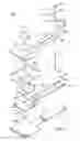
FIG. 1 illustrates an exploded view of the batting technique tool of the present invention;
FIG. 2 illustrates a perspective view of the batting technique tool of the present invention;
FIG. 3 illustrates a bottom view of the bottom platform of the present invention;
FIG. 4 illustrates a side view of the bottom platform of the present invention;
FIG. 5 illustrates a front view of the bottom platform of the present invention;
FIG. 6 illustrates a top view of the turntable of the present invention;
FIG. 7 illustrates a side view of the turntable of the present invention;
FIG. 8 illustrates a top view of the limited travel rotating platform of the present invention;
FIG. 9 illustrates a side view of the limited travel rotating platform of the present invention;
FIG. 10 illustrates a top view of the foot support spacer of the present invention;
FIG. 11 illustrates a top view of the foot support member of the present invention;
FIG. 12 illustrates a top view of another foot support spacer of the present invention;
FIG. 13 illustrates a side view of the foot support spacer of the present invention;
FIG. 14 illustrates a side view of the foot support member of the present invention;
FIG. 15 illustrates a side view of the foot support spacer of the present invention;
FIG. 16 illustrates a top view of the top rotatable platform of the present invention;
FIG. 17 illustrates a side view of the top rotatable platform of the present invention;
FIG. 18 illustrates a top view of the stop for the limited travel rotating platform of the present invention;
FIG. 19 illustrates a side view of the stop for the limited travel rotating platform of the present invention;
FIG. 20 illustrates a top view of the top platform of the present invention;
FIG. 21 illustrates a front view of the top platform of the present invention;
FIG. 22 illustrates a side view of the top platform of the present invention.
DETAILED DESCRIPTION
The Slakey swing Pro or batting technique tool 100 may be used for the development of the muscle memory which may be used to effectively hit a baseball consistently by having the user use the correct form for batting. The back half of the batting technique tool 100 may be used as a platform that is used to support the weight of the user. The batting technique tool 100 may include a rotatable platform to allow the user to rotate the back side of the body to effectively drive a baseball. The front half of the batting technique tool 100 may be an effective combination of a balance beam and foot support that is adjustable for different stride lengths. The front half and the back half may be raised off the support surface in order to prevent the user from placing his/her feet other than on the platform. The balance beam may be used to ensure that the user is balanced for the best possible swing. The front stop on the balance beam may be used to keep the front foot of the player from flying open and keeping the player hitting against the front side. In using the tool of the present invention, the weight of the players should be balanced but more weight may be needed on the backside of the user's body so that the player can drive the ball with the turn of the back foot and hip. The tool of the present invention aides young athletes wanting to learn to hit the ball correctly for their development as a player.
The batting technique tool 100 as illustrated in FIG. 1 may include a foot support member 101 which may be positioned in a spaced relationship to the platform 105 by cooperation with a first and second foot support spacer 103 which may be positioned on opposing sides of a central slot 107 and are slidably and detachably connected to the platform 105 in order to adjust the position of the foot support member 101. The first and second foot support spacer 103 and the foot support member 101 may be detachably connected to the platform 105 by a fastening device 109 which may be a threaded bolt 111, a pair washers 113 and a threaded handle 115 in order to loosen and tighten the foot support member 101 to the platform 105.
The platform 105 may include a top base portion 117 which may be substantially rectangular or any other appropriate shape and a top elongated portion 119 which may extend in substantially the same plane as the base portion 117 outwards to allow the forward foot of the user to remain positioned against the foot support member 101. The elongated portion 119 may include a longitudinal center slot 107 in order to allow the fastening device 109 and the foot support member 101 to move along the elongated portion 119 to allow the user to achieve a comfortable position for the forward foot.
FIG. 1 additionally illustrates a bottom platform 131 which supports the tool 100 on a support surface and opposes the top platform 105 in a spaced relationship. The bottom platform 131 may include a bottom base portion 133 which may correspond to the top base portion 117 and may include a bottom elongated portion 135 which may correspond to the top elongated portion 119.
A turntable 151 (lazy Susan type device) may be positioned on the interior surface of the bottom platform 131 more particularly to the bottom base portion 133, and the turntable 151 may include a substantially circular platform 155 which is substantially parallel to the bottom base portion 133. A limited travel rotating platform 155 may be positioned on the turntable 151 and may cooperate with the circular platform 159 to rotate. The limited travel rotating platform 155 may include a pair of opposing arms 157 which may extend from the limited travel rotating platform 155. The arms 157 limit the travel of the limited travel rotating platform 155 and may limit the travel to substantially 180° to accommodate both a left-handed and a right-handed batter. The limited travel rotating platform may be stop from over rotation by stop 175. A top rotatable platform 159 cooperates with the limited travel rotating platform 155 and rotates with the turntable 151 and extends through the aperture 118 of the top base portion 117 to provide a substantially continuous surface over the top base portion 117 in order to cooperate with the trailing foot of the user/batter, allowing the trailing foot to rotate with the top rotatable platform 159 and providing a satisfactory learning experience for the user.
The top platform 105 may be positioned in a spaced relationship with the bottom platform 131 and the spaced relationship may be maintained with a front spacer 161 which may be connected to a first front side spacer 163 and an opposed second front side spacer 165. The first front side spacer 161 may be connected to a first front connecting spacer 163, and the second front side spacer 165 may be connected to a second front connecting spacer 169. The first front connecting spacer 167 may be connected to a first back side spacer 171 and the second front connecting spacer 169 may be connected to a second back side spacer 173. The first back side spacer 171 and the opposed second back side spacer 173 may be connected to a back spacer 167.
FIG. 2 illustrates a perspective view of the batting technique tool 100 may include a foot support member 101 which may be positioned in a spaced relationship to the platform 105 by cooperation with a first and second foot support spacer 103 which may be positioned on opposing sides of a central slot 107 and are slidably and detachably connected to the platform 105 in order to adjust the position of the foot support member 101. The first and second foot support spacer 103 and the foot support member 101 may be detachably connected to the platform 105 by a fastening device 109 which may be a threaded bolt 111, a pair washers 113 and a threaded handle 115 in order to loosen and tighten the foot support member 101 to the platform 105.
The platform 105 may include a top base portion 117 which may be substantially rectangular or any other appropriate shape and a top elongated portion 119 which may extend in substantially the same plane as the base portion 117 outwards to allow the forward foot of the user to remain positioned against the foot support member 101. The elongated portion 119 may include a longitudinal center slot 107 in order to allow the fastening device 109 and the foot support member 101 to move along the elongated portion 119 to allow the user to achieve a comfortable position for the forward foot.
FIG. 2 additionally illustrates a bottom platform 131 which supports the tool 100 on a support surface and opposes the top platform 105 in a spaced relationship. The bottom platform 131 may include a bottom base portion 133 which may correspond to the top base portion 117 and may include a bottom elongated portion 135 which may correspond to the top elongated portion 119.
A turntable 151 (lazy Susan type device) (not shown) may be positioned on the interior surface of the bottom platform 131 more particularly to the bottom base portion 133, and the turntable 151 (not shown) may include a substantially circular platform 155 (not shown) which is substantially parallel to the bottom base portion 133. A limited travel rotating platform 155 (not shown) may be positioned on the circular platform 151 and may cooperate with the turntable 151 to rotate. The limited travel rotating platform 155 may include a pair of opposing arms 157 (not shown) which may extend from the limited travel rotating platform 155. The arms 157 limit the travel of the limited travel rotating platform 155 and may limit the travel to substantially 180° to accommodate both a left-handed and a right-handed batter. The limited travel rotating platform may be stopped from over rotation by stopped 175 (not shown). A top rotatable platform 159 cooperates with the limited travel rotating platform 155 and rotates with the turntable 151 and extends through the aperture 118 of the top base portion 117 to provide a substantially continuous surface over the top base portion 117 in order to cooperate with the trailing foot of the user/batter, allowing the trailing foot two rotate with the top rotatable platform 159 and providing a satisfactory learning experience for the user.
The top platform 105 may be positioned in a spaced relationship with the bottom platform 131 and the spaced relationship may be maintained with a front spacer 161 which may be connected to a first front side spacer 163 and an opposed second front side spacer 165. The first front side spacer 169 may be connected to a first front connecting spacer 167, and the second front side spacer 167 may be connected to a second front connecting spacer 169. The first front connecting spacer 167 may be connected to a first back side spacer 171 and the second front connecting spacer 169 may be connected to a second back side spacer 173. The first back side spacer 171 and the opposed second back side spacer 173 may be connected to a back spacer 107.
FIG. 3 illustrates a bottom view of the bottom platform 131 which may include the bottom base portion 133 and the bottom elongated portion 135.
FIG. 4 illustrates a side view of the bottom platform 131 which may include the bottom base portion 133 and the bottom elongated portion 135.
FIG. 5 illustrates a front view of the bottom platform 131.
FIG. 6 illustrates a top view of the turntable 151 and the rotatable platform 151.
FIG. 7 illustrates a side view of the turntable 151.
FIG. 8 illustrates a top view of the limited travel rotating platform 155 which may include the arms 157.
FIG. 9 illustrates a side view of the limited travel rotating platform 155.
FIG. 10 illustrates a top view of the first foot support spacer 103 and FIG. 13 illustrates a front view of the foot support spacer 103.
FIG. 11 illustrates a top view of the foot support member 101 and FIG. 14 illustrates a front view of the foot support member 101.
FIG. 12 illustrates a top view of a second foot support spacer 103 and FIG. 15 illustrates a front view of the second foot support spacer 103.
FIG. 16 illustrates a top view of the top rotatable platform 159 and FIG. 17 illustrates a front view of the top rotatable platform 159.
FIG. 18 illustrates a top view of the stop for the limited travel rotating platform 175 and FIG. 19 illustrates a front view of the stop for the limited travel rotating platform 175.
FIG. 20 illustrates the top platform 105 which may include a top base portion 117 and a top elongated portion 119 which may have a central slot 107. The top base portion 117 may have an opening 181 to cooperate with the top rotatable platform 159 (not shown).
FIG. 21 illustrates a front view of the top platform 105 which may include the top base portion 117 and the top elongated portion 119.
FIG. 22 illustrates a side view of the top platform 105, the base portion 117, and the top elongated portion 119.
While the invention is susceptible to various modifications and alternative forms, specific embodiments thereof have been shown by way of example in the drawings and are herein described in detail. It should be understood, however, that the description herein of specific embodiments is not intended to limit the invention to the particular forms disclosed.
Claims
1) A batting technique tool to teach a user to bat properly, comprising:
a top platform having a top base portion and a top elongated portion;
the base portion having a rotatable platform to rotate in two directions to accommodate a traveling foot of the user;
the top elongated portion having a movable foot support member to accommodate the forward foot of the user.
2) A batting technique tool to teach a user to bat properly as in claim 1, wherein the movable foot support member is slidably connected to the top elongated portion.
3) A batting technique tool to teach a user to bat properly as in claim 1, wherein the rotatable platform is connected to a limited travel rotating platform to limit the travel of the rotatable platform.
4) A batting technique tool to teach a user to bat properly as in claim 3, wherein the limited travel rotating platform is connected to a turntable.
5) A batting technique tool to teach a user to bat properly as in claim 1, wherein the batting technique tool includes an opposing bottom platform.
6) A batting technique tool to teach a user to bat properly as in claim 5, wherein the bottom platform includes a bottom base portion.
7) A batting technique tool to teach a user to bat properly as in claim 5, wherein the bottom platform includes a bottom elongated portion.
Images & Drawings included:


Sources:
- United States Patent and Trademark Office - verify current appl. status at the USPTO↗
Recent applications in this class:
- » 20250135311 2025-05-01
HITTING TOOL SELECTION DIAGNOSIS SYSTEM, HITTING TOOL SELECTION DIAGNOSIS METHOD, AND NON-TRANSITORY COMPUTER-READABLE MEDIUM STORING DIAGNOSIS PROGRAM - » 20250114680 2025-04-10
BATTING TEE ADAPTER AND SYSTEM - » 20250083017 2025-03-13
BASEBALL AND SOFTBALL TRAINING DEVICE FOR IMPROVED SPIN RATE AND EFFICIENCY - » 20250083016 2025-03-13
Throwing Footwork Trainer - » 20250073552 2025-03-06
BALL PRESSURE MEASUREMENT SYSTEM AND METHOD - » 20250065205 2025-02-27
Baseball Batting Training Assembly - » 20250065204 2025-02-27
PITCH TRAINING DEVICE - » 20250032877 2025-01-30
SHOCK ABSORBING DEFORMABLE SPORTING SUPPORT APPARATUS - » 20250032876 2025-01-30
TRAINING BAT APPARATUS - » 20250025759 2025-01-23
Baseball Grip Training Device